Table of Contents
Advertisement
Quick Links
Advertisement
Table of Contents

Subscribe to Our Youtube Channel
Summary of Contents for PCB Piezotronics IMI SENSORS 643A62
- Page 1 Model 643A62 4-20 mA Output Velocity Sensor Installation and Operating Manual For assistance with the operation of this product, contact PCB Piezotronics, Inc. Toll-free: 800-959-4464 24-hour SensorLine: 716-684-0001 Fax: 716-684-3823 E-mail: imi@pcb.com Web: www.imi-sensors.com...
- Page 2 Returning Equipment – Following the equipment to PCB Piezotronics for these procedures will insure that your repair. User servicing or repair is not returned materials are handled in the recommended and, if attempted, may most expedient manner.
- Page 3 PCB Piezotronics, Inc. Warranty – All equipment and repair 3425 Walden Ave. services provided by PCB Piezotronics, Depew, NY 14043 USA Inc. are covered by a limited warranty Toll-free: (800) 828-8840 against defective...
- Page 4 Model 642/643/647/648 A Series Industrial 4-20mA Sensor Operating Guide with Enclosed Warranty Information 3425 Walden Avenue, Depew, New York 14043-2495 Phone (716) 684-0003 Fax (716) 684-3823 Toll Free Line 1-800-959-4IMI MANUAL NUMBER: 25778 MANUAL REVISION: C ECN NUMBER: xxxxx...
-
Page 5: Table Of Contents
Table of Contents Introduction ........................Page 3 General Features Dimension Drawing......................Page 4 Operation and Wiring....................... Page 5 Standard Wiring Taking Measurements RV Option TO Option Installation........................Page 9 ESD Sensitivity ......................Page 10 Warranty/Servicing Warranty, Service & Return Procedure................Page 11 Customer Service ...................... -
Page 6: Introduction
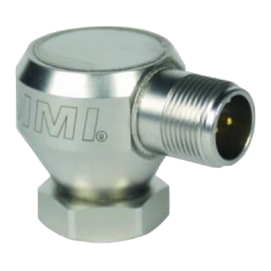
Introduction The Model 642/643/647/648 A Series Industrial 4-20mA Sensors combine the capabilities of a piezoelectric vibration sensor and a 4-20mA vibration transmitter. The sensor outputs a 4-20mA signal that is proportional to the overall velocity or acceleration of the machinery. Ideal for monitoring the vibration of process equipment such as fans, motors and pumps, the output of the sensor is used for process control or predictive maintenance. -
Page 7: Dimension Drawing
Dimension Drawing 1.24 [ 31.5] ELECTRICAL CONNECTOR 5/8-24 UNEF-2A 2 - PIN (MIL-C-5015) 1.98[45.7] PIN A: PIN B: POSITIVE NEGATIVE 4-20 mA 4-20 mA 1.41 [35.8] 1.05 [26.7] 7/8 (22) HEX 3/4-16 UNF-2A 1/8" HEX ALLEN KEY REQUIRED MOUNTING STUD MODEL 080A162 1/4-28 UNF-2A (SUPPLIED) -
Page 8: Operation And Wiring
Operation and Wiring Standard Wiring The Model 642/643/647/648 A Series operates from a standard 2-wire, 4-20mA loop. If using a loop powered unit, attach the positive (+) input from the power supply to Pin A or Red wire on the sensor and the negative (-) input from the power supply to Pin B or Blue wire of the sensor. -
Page 9: Taking Measurements
Taking Measurements When measuring the current output from the unit, use the following formula to calculate the vibration level: Vibration Output = (Measured Output – 4mA) x (Full Scale Vibration Output /16mA) Measured mA 642AX0 642AX1 642AX2 4.00 0.0 ips, pk 0.0 ips, pk 0.0 ips, pk 8.00... -
Page 10: Rv Option
RV Option The RV (raw vibration) option includes a 100mV/g ±20% additional output. The accelerometer frequency range is 1 Hz-10 kHz, maximum amplitude of 15 g-pk. Data collectors or analyzers can use this vibration signal for further analysis. Figure 3 – RV wiring For integral cable sensors: 4-20mA Positive BLACK... -
Page 11: To Option
TO Option The TO (Temperature Output) option includes an additional independent 4-20mA output for temperature measurement. The temperature range is from -40°C to 125°C with an overall accuracy of ±5%FSO. The imbedded temperature sensor monitors the environment internal to the sensor housing and is situated at approximately mid level. -
Page 12: Installation
Installation Installation should be performed per the following detail drawing for best performance. PAGE 9... -
Page 13: Esd Sensitivity
Warning 2 – ESD sensitivity This equipment is designed with user safety in mind; however, the protection provided by the equipment may be impaired if the equipment is used in a manner not specified by PCB Piezotronics, Inc. Caution 1 – ESD sensitivity Cables can kill your equipment. -
Page 14: Warranty, Service & Return Procedure
Warranty IMI instrumentation is warranted against defective material and workmanship for 1 year unless otherwise expressly specified. Damage to instruments caused by incorrect power or misapplication, is not covered by warranty. If there are any questions regarding power, intended application, or general usage, please consult with your local sales contact or distributor. -
Page 15: Customer Service
Customer Service IMI, a division of PCB Piezotronics, guarantees Total Customer Satisfaction. If, at any time, for any reason, you are not completely satisfied with any IMI product, IMI will repair, replace, or exchange it at no charge. You may also choose to have your purchase price refunded. - Page 16 Model Number Revision: A 4-20 MA OUTPUT VELOCITY SENSOR 643A62 ECN #: 43341 Performance ENGLISH OPTIONAL VERSIONS Measurement Range 0.0 to 2 in/sec rms 0 to 50.8 mm/s rms Optional versions have identical specifications and accessories as listed for the standard model Output 4-20 mA 4-20 mA...
- Page 17 PCB Piezotronics Inc. claims proprietary rights in REVISIONS the information disclosed hereon. Neither it nor any reproduction thereof will be disclosed to others DESCRIPTION without the written consent of PCB Piezotronics Inc. ADDED METRIC MOUNTING INFORMATION 43341 METRIC MOUNTING HOLE PREPARATION: ...
- Page 18 PCB Piezotronics Inc. claims proprietary rights in REVISIONS the information disclosed hereon. Neither it nor any reproduction thereof will be disclosed to others DESCRIPTION without the written consent of PCB Piezotronics Inc. UPDATED NOTE 1 43341 INTEGRAL ARMOR JACKET (MOLDED 2 CONDUCTOR ...


Need help?
Do you have a question about the IMI SENSORS 643A62 and is the answer not in the manual?
Questions and answers