
Related Manuals for SOYO SC-5EA5


Summary of Contents for SOYO SC-5EA5
- Page 1 SC-5EA5 SURIA ETEQ 512Kb PB Cache Mainboard User & Technical Reference Giude Factory Part # 5EA5/A5C...
-
Page 2: Table Of Contents
Table of Contents Chapter 1: Introduction… … … .… … … … ..… .… … … ..1 Key Features………………………………..…………………1 Unpacking the Mainboard…………………………………2 Electrostatic Discharge Precautions……………………….2 Mainboard Layout W/ Default Settings……..…………………3 Remarks on the Cyrix and IBM P200 CPUs……..………….5 Voltage Setting List……………………………………………5 Chapter 2: Hardware Setup.…... - Page 3 J17-Keylock & Power LED Connector……………………..16 IDE1/IDE2 - Onboard Primary/Secondary IDE Connectors.16 CN1-PS/2 Mouse Connector…………………………..16 PRT-Parallel Port Connector…………………………..16 AT Power Conn. - AT power supply connector……..16 J23: Sleep Switch Connector Enable/Disable…………….17 CN3-Universal Serial Bus Connectors……………………17 J18 speaker………………………………………………..17 Chapter 3: BIOS setup… … ..… .… … … ..… … … .… … ..18 St a n da r d CM OS Se t up……...
-
Page 4: Chapter 1: Introduction
1 Introduction The EQ82C661X PCI mainboard is a high-performance AT form-factor system board that supports P54C/P55C family CPUs. You can order 512K of external cache memory on the mainboard. The mainboard is fully compatible with industry standards, and adds many technical enhancements. -
Page 5: Unpacking The Mainboard
Introduction Unpacking the Mainboard The mainboard package contains: ¥ The EQ82C661X Mainboard ¥ This UserÕs Guide Note: Do not unpack the mainboard until you are ready to install it. Follow the precautions below while unpacking the mainboard. 1. Before handling the mainboard, ground yourself by grasping an unpainted portion of the systemÕs metal chassis. -
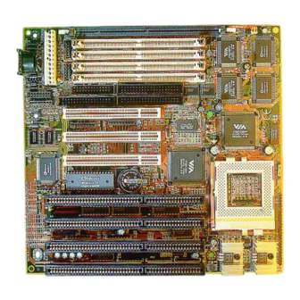
Page 6: Mainboard Layout W/ Default Settings
Introduction Mainboard Layout w/ Default Settings Figure 1Ð1. Mainboard Layout 1. ZIF socket 7 (for P54C/P55C) 10. SIMM Bank 2. EQ82C661X Chipset 11. Floppy Connector 3. Pipelined Burst SRAM 12. IDE1/IDE2 Connector 4. Super I/O Chip 13. Parallel Port Connector 5. - Page 7 Introduction Default settings are as follows: Pentium 133MHz (P54C) CPU , 512K Pipelined Burst cache , On - board PCI E - IDE Enabled , 2 high speed UARTS Enabled (w / 16550 FIFO), 1 EPP/ECP port (ECP + EPP mode), 5V DRAM/3.3V DIMM, and AT power supply.
-
Page 8: Remarks On The Cyrix And Ibm P200 Cpus
Introduction Remarks on the Cyrix and IBM P200 CPUs Please note that if you use a Cyrix or IBM P200 CPU, you will have to set the frequency to 75MHz. You will also have to set JP16, the PCI bus frequency jumper to asynchronous to have the PCI bus run on 32MHz, in order to avoid problems with add-on cards. -
Page 9: Chapter 2: Hardware Setup
2 Hardware Setup This chapter is designed for Normal edition mainboard use only and it explains how to configure the mainboardÕs hardware. After you install the mainboard, you can set jumpers, install memory on the mainboard, and make case connections. Refer to this chapter whenever you upgrade or reconfigure your system. -
Page 10: Jp16: Pci Bus Asynchronous/Synchronous Jumper
Hardware Setup JP16: PCI Bus Asynchronous/Synchronous Jumper Asynchronous and synchronous (default) PCI bus frequency settings are available. PCI Bus Setting JP16 Asychronous Synchronous Divides the host bus by 2 to get the Asynchronous setting, and sets the PCI bus on 32MHz to get the synchronous setting. Set JP16 to Synchronous mode when the system is unstable. -
Page 11: Cpu Type Configuration
Hardware Setup CPU Type Configuration This section is designed for normal edition manboard use only and also shows you how to configure your CPU step by step. Note that you need to check the CPU voltage before installation. Step 1: Frequency Setting Pentium –... - Page 12 Hardware Setup EQ6619 JP12 JP11 JP12 JP10 JP11 JP10 JP12 JP11 JP10 EQ6618 JP12 JP11 JP10 JP14 JP13 JP12 JP11 JP10 JP12 JP11 JP10 Figure 2-1-2. CPU Jumper Settings stability.
- Page 13 Hardware Setup Pentium– 150/166 CPU Settings (2.5 x clock) AMD K5/K6 – PR166 CPU Setting EQ6619 JP12 JP11 Pentium – 150/60 MHz JP10 JP12 JP11 JP10 EQ6618 Pentium – 166/66 MHz AMD K5/K6 – PR166 Family JP12 JP14 JP11 JP10 JP13 Figure 2Ð1Ð3.
- Page 14 Hardware Setup JP12 JP11 JP10 JP14 JP13 Figure 2-1-2. CPU Jumper Settings Figure 2-1-2. CPU Jumper Settings stability. stability. JP12 JP11 JP10 JP14 JP15 JP13 Figure 2-1-3. CPU Jumper Settings stability.
- Page 15 Single voltage CPUs use the same voltage for both Vio and Vcore. The CPUs that fall into this category are : P54CX , AMD-K5 and the Cyrix 6x86. Refer to the following figures to set the voltage for these CPUs: JP32 JP31 Family...
- Page 16 Dual voltage CPUs are designed to use different voltages for Vio and Vc ore. They include P55CX and the Cyrix 6x86L / 6x86MX. Refer to the following figure to set the voltage for these CPUs: 3.2V CPU 2.9V CPU JP32 2.8V CPU JP31 Family...
- Page 17 1. In Bank 1 2. In Bank 2 3. In Bank 1 & Bank 2 4. In DIMM 5. In Bank 2& DIMM Cacheable Cache Size Cache RAM TAG RAM Range 512KB...
-
Page 18: Multi I/O Port Addresses
Hardware Setup Multi I/O Port Addresses Default settings for multi I/O port addresses are shown in the table below. Port I/O Address Status LPT1* 378H ECP + EPP COM1 3F8H COM2 2F8H If default I/O port addresses conflict with other I/O cards (e.g. sound cards or I/O cards ) , you must adjust one of the I/O addresses to avoid address conflict. -
Page 19: Cn5-Ir Connector
Hardware Setup CN5 - IR Connector Attach a 5-pin infrared device cable to this connector for enabling the infrared transfer function. This mainboard meets the specification of ASKIR and HPSIR. CN2 - Keyboard Connector A 5-pin female DIN keyboard connector is located at the rear of the board. Plug the keyboard jack into this connector. -
Page 20: J23: Sleep Switch Connector Enable/Disable
Hardware Setup J23: Sleep Switch Connector Enable/Disable Toggle this jumper to force the system into power saving (green) mode. Any hardware IRQ signal will cause the system to wake up. CN3: Universal Serial Bus Connectors Attach a 9 pin USB cable to these connectors to connect external USB devices to the mainboard. -
Page 21: Chapter 3: Bios Setup
3 BIOS Setup The mainboardÕs BIOS setup program is the ROM PCI/ISA BIOS from Award Software Inc. Enter the Award BIOS programÕs Main Menu as follows: 1. Turn on or reboot the system. After a series of diagnostic checks, you are asked to press DEL to enter Setup. 2. -
Page 22: St A N Da R D Cm Os Se T
BIOS Setup Standard CMOS Setup Run the Standard CMOS Setup as follows. 1. Choose ÒSTANDARD CMOS SETUPÓ from the Main Menu. A screen appears. ROM PCI/ISA BIOS STANDARD CMOS SETUP AWARD SOFTWARE, INC. Date (mm:dd:yy) : Fri, Feb 1 1995 Time (hh:mm:ss) : 7 : 30 : 33 HARD DISKS... - Page 23 BIOS Setup Primary Large Ð Large IDE hard disk (for certain (Secondary) hard disk) Master & Slave Note: If you have any questions on your hard (Continued) disk type or mode, ask your hard disk provider or previous user for details. Drive A &...
-
Page 24: Bi O S F E A T U R E S S E T U
BIOS Setup BIOS Features Setup Run the BIOS Features Setup as follows. 1. Choose ÒBIOS FEATURES SETUPÓ from the Main Menu and a screen with a list of items appears. (The screen below shows the BIOS default settings.) ROM PCI/ISA BIOS BIOS FEATURES SETUP AWARD SOFTWARE, INC. - Page 25 BIOS Setup Boot Sequence Choose the boot device sequence as your need. For example, ÒA, C, SCSIÓ means BIOS will look for an operating system first from drive A, drive C, then SCSI device. Options of this function are: A, C, SCSI C, A, SCSI C, CDÐROM, A CDÐROM, C, A...
- Page 26 BIOS Setup IDE Second Default setting is Enabled. Choose Disabled when Channel you need to turn off the onboard IDE second Control channel. PS/2 Mouse Default setting is Disabled. You need to enable this Function function when the PS/2 mouse is attached. Control PCI/VGA Enabled: The color of the monitor may be incorrect...
-
Page 27: Chipset Features Setup
BIOS Setup Chipset Features Setup The Chipset Features Setup option changes the values of the chipset registers. These registers control system options in the computer. Note: Change these settings only if you are familiar with the Chipset. Run the Chipset Features Setup as follows. 1. - Page 28 BIOS Setup SDRAM Cycle Length 2 (default). This function is shown only when uses SDRAM. Read Pipeline Use the default setting. Write Pipeline Use the default setting. Video BIOS Cacheable Disabled Ð The ROM area F0000H- FFFFFH is not cached. Enabled Ð...
-
Page 29: P O W E R M A N A G E M E N T S E T U
BIOS Setup Power Management Setup The Power Management Setup option sets the systemÕs power saving functions. Run the Power Management Setup as follows. 1. Choose ÒPOWER MANAGEMENT SETUPÓ from the Main Menu and a screen with a list of items appears. ROM PCI/ISA BIOS CMOS SETUP UTILITY POWER MANAGEMENT SETUP... - Page 30 BIOS Setup PM Control by Choose Yes (default) or No. APM stands for Advanced Power Management. To use APM, you must run Òpower.exeÓ under DOS v6.0 or later version. Video Off Option Susp, Stby→off:Video off when the system runs into Suspend or Standby mode.
- Page 31 BIOS Setup LPT & COM Choose LPT/COM (default) or LPT (COM) to enable the power management timer. Choose NONE to disable the power management timer. HDD &FDD Choose On (default) to enable the power management timer, or Off to disable the power management timer.
-
Page 32: Pnp/ P Ci Con Fi Gu R A T I On Set
BIOS Setup PNP/PCI Configuration Setup This option sets the mainboardÕs PCI Slots. Run this option as follows: 1. Choose ÒPNP/PCI CONFIGURATION SETUPÓ from the Main Menu and the following screen appears. (The screen below shows default settings.) ROM PCI/ISA BIOS PNP/PCI CONFIGURATION AWARD SOFTWARE, INC. - Page 33 BIOS Setup IRQX and Choose PCI/ISA PnP or Legacy ISA. If the first DMAX assigned item is set to Manual, you could choose IRQX and DMAX assigned to PCI/ISA PnP card or ISA card. PCI IRQ Choose Edge or Level. Most PCI trigger signals Activated By are Level.
-
Page 34: Loa D S E T U P D E Fa U L T
BIOS Setup Load Setup Defaults This item loads the system values you have previously saved. Choose this item and the following message appears: ÒLoad SETUP Defaults (Y/N)? NÓ To use the SETUP defaults, change the prompt to ÒYÓ and press <Enter>. -
Page 35: I N T E G R A T E D P E R I P H E R A L
BIOS Setup Integrated Peripherals The Integrated Peripherals option changes the values of the chipset registers. These registers control system options in the computer. Note: Change these settings only if you are familiar with the Chipset. Run the Integrated Peripherals as follows. 1. - Page 36 BIOS Setup IDE Primary Master PIO/ Choose Auto (default) or mode 0~4. IDE Primary Slave PIO/ Mode 0 is the slowest speed, and HDD IDE Secondary Master mode 4 is the fastest speed. For better PIO/ performance and stability, we suggest IDE Secondary Slave PIO you use the Auto setting to set the HDD control timing.
-
Page 37: Su P E R Vi S Or P A S S Wor
BIOS Setup Parallel Port Mode Choose ECP + EPP (default), Normal or EPP, ECP mode. The mode depends on your external device that connects to this port. ECP Mode Use DMA Choose DMA3 (default) or DMA1. This setting only works when the Onboard Printer Mode is set at the ECP mode. -
Page 38: U S E R P A S S W O R
BIOS Setup User Password Based on the setting you made in the ÒSecurity OptionÓ of the ÒBIOS FEATURES SETUPÓ, this Main Menu item lets you configure the system so that a password is required every time the system boots or an attempt is made to enter the Setup program. -
Page 39: I D E Hd D A U T O D E T E C T I
BIOS Setup IDE HDD Auto Detection This Main Menu item automatically detects the hard disk type and configures the STANDARD CMOS SETUP accordingly. This function is only valid for IDE hard disks. Note: ROM PCI/ISA BIOS CMOS SETUP UTILITY AWARD SOFTWARE, INC. HARD DISKS TYPE SIZE... -
Page 40: Appendix A: Jumper For Cyrix/Ibm Cpu(J100)
Appendix A Jumper for Cyrix/IBM CPU (J100) The SY-5EAS mainboard has a new jumper (J100) for better performance with Cyrix/IBM CPUs. Here is explaination for you on how to use this jumper correctly. l Leave J100 open when you want to install a non-Cyrix /IBM CPU (default setting), or short J100 when you want to install a Cyrix CPU. - Page 41 Appendix B : Quick Installation Guide This leaflet is meant to help you set the jumpers for your 5EAS motherboard in order to boot the motherboard. Please refer to Diagram 1 for the location of the relevant jumpers: Diagram 1: Board layout Table 1 : Jumper settings for CPU voltage and frequency...
- Page 42 Quick Installation Guide (continued) Table 3 : Settings for various processors SETTINGS CPU Frequency JP10, 11, 12 / JP 13, 14 processor bus clock multiplier JP10 JP11 JP12 JP13 JP14 AMD K5 PR75 50 Mhz 1.5x open open AMD K5 PR90 60 Mhz 1.5x open...
Need help?
Do you have a question about the SC-5EA5 and is the answer not in the manual?
Questions and answers