
Related Manuals for FlameStop VESDA-E VEU-A00


Summary of Contents for FlameStop VESDA-E VEU-A00
- Page 1 VESDA-E VEU-A00 Product Guide April 2016 Document: 22061_10 Part Number: 30275 AUTHORISED DISTRIBUTOR OF VESDA www.flamestop.com.au | sales@flamestop.com.au...
- Page 3 If any provision outlined above is found to be invalid or unenforceable by a court of law, such invalidity or unenforceability will not affect the remainder which will continue in full force and effect. All rights not expressly granted are reserved. AUTHORISED DISTRIBUTOR OF VESDA www.flamestop.com.au | sales@flamestop.com.au...
- Page 4 VESDA-E VEU-A00 Product Guide Scope The VESDA-E VEU-A00 Product Guide provides a comprehensive description of the VESDA-E VEU-A00 detector and its accessories. This guide introduces the VEU-A00 features, technical specifications and gives an understanding of its components and their function. You will also find instructions on installing, cabling and powering up the detector.
- Page 5 The product is not intended to be mounted in hostile environments but is able to sample from hostile environments. AS1851.1 2005 Maintenance Standards. Wherever this document and the AS1851.1 differ, AS1851.1 should be followed in preference to this document. AUTHORISED DISTRIBUTOR OF VESDA www.flamestop.com.au | sales@flamestop.com.au...
- Page 6 The flow through the detector predicted by ASPIRE must be greater than 20 L/m. Additional information: The VESDA-E VEU-A00 passed the EN 54-20 fire tests with the following configurations: Class A with 80 holes and a Fire-1 setting of 0.015% obs/m Class B with 80 holes and a Fire-1 setting of 0.026% obs/m...
-
Page 7: Table Of Contents
Replacing the Aspirator Replacing the Smoke Detection Chamber Replacing the Sampling Module Spare Parts Troubleshooting Fault Reporting through Relays Troubleshooting with Xtralis VSC Commissioning Forms VEU-A00 Detector Commissioning Configuration ASPIRE Data Smoke Test AUTHORISED DISTRIBUTOR OF VESDA www.flamestop.com.au | sales@flamestop.com.au... - Page 8 VESDA-E VEU-A00 Product Guide Air Sampling Test Results Glossary Index AUTHORISED DISTRIBUTOR OF VESDA www.flamestop.com.au | sales@flamestop.com.au...
-
Page 9: Introduction
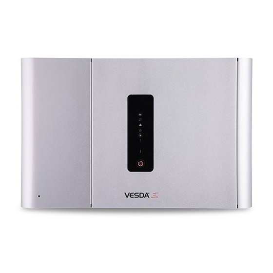
VESDA-E VEU-A00 Product Guide Introduction The VESDA-E VEU-A00 is an aspirating smoke detector (ASD) that provides very early warning of fire conditions by drawing air samples through an air sampling pipe network. Figure 1-1: VESDA-E VEU-A00 Aspirating Smoke Detector The detector easily interfaces with fire warning and fire suppression release systems, and can be integrated into a building management system (BMS). - Page 10 VESDA-E VEU-A00 Product Guide This page is intentionally left blank. AUTHORISED DISTRIBUTOR OF VESDA www.flamestop.com.au | sales@flamestop.com.au...
-
Page 11: Product Information
USB interface is provided for initial setup. The detector has a LED user interface. A series of LEDs display Alarm, Fault, Disable and detector power on status. A button allows the user to Reset or Disable the detector. AUTHORISED DISTRIBUTOR OF VESDA www.flamestop.com.au | sales@flamestop.com.au... -
Page 12: Front Panel
Status LEDs: Alert, Action, Fire 1, Fire 2, Disabled, Fault and Power. Controls: Reset and Disable button. 2.3.1 Status LEDS The VESDA-E VEU-A00 detector features a range of LED Indicators which illuminate when their respective activation conditions are met. Table 2-1: LED Indicators Symbol... -
Page 13: Internal Buttons
USB port, and the user is required to enter it when creating an Ethernet connection profile in Xtralis VSC. It is also necessary to enter additional PIN codes to access administrative and distributor functions. Refer to Section 5.3 on page 54 for further information. AUTHORISED DISTRIBUTOR OF VESDA www.flamestop.com.au | sales@flamestop.com.au... -
Page 14: Vesdanet
The VEU-A00 detector also provides a gateway to the VESDAnet for a PC running Xtralis VSC connected to the VEU-A00 via Ethernet, USB or WiFi. Refer to the VESDA Communications Guide for further information on VESDAnet network connectivity. AUTHORISED DISTRIBUTOR OF VESDA www.flamestop.com.au | sales@flamestop.com.au... -
Page 15: Specifications
Screw terminal blocks (0.2-2.5 sq mm, 24-14 AWG) Interfaces USB (Type 2) Ethernet (RJ45) WiFi, 802.11 b/g/n Dynamic Range 0.0002%/m (0.00006%/ft) to 32%/m (10%/ft) Sensitivity Range 0.001 to 20% obs/m (0.0003 to 6.25% obs/ft.) AUTHORISED DISTRIBUTOR OF VESDA www.flamestop.com.au | sales@flamestop.com.au... - Page 16 Two Fault Warning Levels Maintenance and Major Fault Maintenance Aids Filter and flow monitoring Event reporting via VESDAnet and event log Table 2-4: Ordering Information VESDA-E VEU-A00 Detector VEU-A00 Exhaust Adaptor US VSP-961 Note: Refer to Section Table 7-2 for the spare parts list.
-
Page 17: Dimensions
1.34 26.5 1.04 J 350.05 13.78 224.0 8.82 230.2 9.06 M 135.48 N 132.28 5.21 28.5 1.12 35.0 1.38 45.0 1.77 127.0 143.0 5.63 26.0 1.02 Figure 2-4: Front, top, bottom and side dimensions AUTHORISED DISTRIBUTOR OF VESDA www.flamestop.com.au | sales@flamestop.com.au... - Page 18 VESDA-E VEU-A00 Product Guide inch 17.5 0.69 315.0 12.4 17.5 0.69 D 144.99 5.71 77.2 3.04 Figure 2-5: Rear dimensions with Mounting Bracket AUTHORISED DISTRIBUTOR OF VESDA www.flamestop.com.au | sales@flamestop.com.au...
- Page 19 VESDA-E VEU-A00 Product Guide inch 224.0 8.82 112.0 4.41 40.9 1.61 D 268.39 10.57 40.71 20.25 183.5 7.22 20.25 Figure 2-6: Rear Dimensions with hole locations for direct mounting AUTHORISED DISTRIBUTOR OF VESDA www.flamestop.com.au | sales@flamestop.com.au...
- Page 20 VESDA-E VEU-A00 Product Guide This page is intentionally left blank. AUTHORISED DISTRIBUTOR OF VESDA www.flamestop.com.au | sales@flamestop.com.au...
-
Page 21: Pipe Network Design And Installation
Determine the pipe inlet ports to be used. Refer to Table 3-1 below for details. Remove the plugs from only those pipe inlet ports intended for use. To remove the plug, place a large AUTHORISED DISTRIBUTOR OF VESDA www.flamestop.com.au | sales@flamestop.com.au... -
Page 22: Managing The Exhaust Air
For example, where pressure differences exceed 50 Pa, or where hazardous substances are present inside the protected environment. Return air pipes need to be as short as possible to minimize the effect of airflow impedance in the return air pipe network. AUTHORISED DISTRIBUTOR OF VESDA www.flamestop.com.au | sales@flamestop.com.au... -
Page 23: Installation
VESDA-E VEU-A00 Product Guide Installation The VEU-A00 detector is shipped with the following components: 1 VESDA-E VEU-A00 detector Installation Sheet Mounting bracket Mounting template for directly mounting the detector to the mounting surface Exhaust Adaptor (US only) 1 End of Line resistor for the monitored GPI Check all components for damage and refer any concerns to your authorized representative. -
Page 24: Mounting
A minimum clearance of 20 mm (0.8 in.) is required between the detector and a wall or obstruction, on both sides of the detector. Refer to Section 4.2.3 for further information. Figure 4-4: Mounting location AUTHORISED DISTRIBUTOR OF VESDA www.flamestop.com.au | sales@flamestop.com.au... - Page 25 2. Open the front door and remove the fascia. Refer to Sections 7.2 on page 78 and 7.4 on page 82 for further information. Figure 4-5: Detector with fascia removed 3. Take the top and bottom covers off. To do this, press the tabs marked A and B in Figure 4-6. AUTHORISED DISTRIBUTOR OF VESDA www.flamestop.com.au | sales@flamestop.com.au...
- Page 26 Figure 4-6: Tabs used to remove top and bottom cover 4. Detach the tethers, Figure 4-7 and Figure 4-8. (You can leave the cables from the detector to the fascia connected.) Figure 4-7: Detaching the tethers AUTHORISED DISTRIBUTOR OF VESDA www.flamestop.com.au | sales@flamestop.com.au...
- Page 27 VESDA-E VEU-A00 Product Guide Figure 4-8: Detector with tethers detached 5. Detach the front door from the fascia by removing pin A from the hinge (Figure 4-9, Figure 4-10). Leave pin B in place – do not remove it. AUTHORISED DISTRIBUTOR OF VESDA www.flamestop.com.au | sales@flamestop.com.au...
- Page 28 VESDA-E VEU-A00 Product Guide Figure 4-9: Removing door hinge pin A Figure 4-10: Detaching door AUTHORISED DISTRIBUTOR OF VESDA www.flamestop.com.au | sales@flamestop.com.au...
- Page 29 Rotate the door 180 degrees and place it next to the right side of the fascia. 7. Replace the door hinge pin. (Figure 4-12, Figure 4-13) Figure 4-11: Rotate detector and door and move door to right side of fascia AUTHORISED DISTRIBUTOR OF VESDA www.flamestop.com.au | sales@flamestop.com.au...
- Page 30 VESDA-E VEU-A00 Product Guide Figure 4-12: Replacing the door hinge pin - showing correct positioning of door and pin AUTHORISED DISTRIBUTOR OF VESDA www.flamestop.com.au | sales@flamestop.com.au...
- Page 31 Figure 4-14: Correct positioning of door hinge pin when fully in place 8. Re-attach the tethers. Attach at the slots circled in Figure 4-15. Position the tethers in the slots and pull up as shown in Figure 4-16. Figure 4-15: Re-attach tethers at circled positions AUTHORISED DISTRIBUTOR OF VESDA www.flamestop.com.au | sales@flamestop.com.au...
- Page 32 11. The detector is now inverted. The display should be upright while the exhaust vent is at the top and sampling pipe inlets at the bottom. The electrical connections and filter should be accessible by opening the door. AUTHORISED DISTRIBUTOR OF VESDA www.flamestop.com.au | sales@flamestop.com.au...
- Page 33 3. Insert two screws into the mounting surface at marked positions (Figure 4-19). 4. Slide plate onto the mounting screws and tighten them with a screwdriver (B). Legend A Mounting bracket B Screwdriver Figure 4-19: Tighten screws AUTHORISED DISTRIBUTOR OF VESDA www.flamestop.com.au | sales@flamestop.com.au...
- Page 34 7. Open the door on the front of the detector (Figure 4-22). Refer to Section 7.2 on page 78 for further information on how to open the door. 8. Insert and tighten the locking screw (A). This secures the detector to the mounting bracket. Legend A Locking screw Figure 4-22: Locking Screw AUTHORISED DISTRIBUTOR OF VESDA www.flamestop.com.au | sales@flamestop.com.au...
- Page 35 For metric pipes, cut the pipe to the inner depth line marked on the mounting template. For imperial pipes, fit the pipe adaptor (C) and cut the pipe to the outer depth line marked on the mounting template. 7. Position electrical conduit (D) on the marked center lines. AUTHORISED DISTRIBUTOR OF VESDA www.flamestop.com.au | sales@flamestop.com.au...
- Page 36 Position the right keyhole on the rear of the detector over the head of the right screw (A) (Figure 4-27). Upright Inverted Detector Detector Figure 4-27: Position detector over screw Slide the detector to the left, or to the right for inverted detectors, to lock the detector on the screw (Figure 4-28). AUTHORISED DISTRIBUTOR OF VESDA www.flamestop.com.au | sales@flamestop.com.au...
- Page 37 Rotate the detector anticlockwise, or clockwise for an inverted detector, to lock the detector on to the screw (Figure 4-30). Upright Inverted Detector Detector Figure 4-30: Rotate the detector 12. Insert an M4 screw at the small end of the detector’s bottom-left, or bottom-right for an inverted detector, keyhole (Figure 4-31). AUTHORISED DISTRIBUTOR OF VESDA www.flamestop.com.au | sales@flamestop.com.au...
- Page 38 VESDA-E VEU-A00 Product Guide Upright Detector Inverted Detector Figure 4-31: Locking screw 13. Tighten the top and bottom screws. 14. Insert the pipes and electrical conduit. AUTHORISED DISTRIBUTOR OF VESDA www.flamestop.com.au | sales@flamestop.com.au...
-
Page 39: Wiring
VEU-A00. 4.3.1 Cabling Inlets The VESDA-E VEU-A00 contains four inlets for power, relay and network cabling, located on the upper and lower sides of the detector base. The holes have a diameter of 26 mm (1.02 inch). Note: To maintain the specified IP rating, cable glands or conduit must be used. - Page 40 Le détecteur de fonctionnement lorsque la tension d'alimentation DC est en dehors de la plage de tension spécifiée peut endommager les composants internes. Pour plus d'informations, se reporter au notice descriptive du produit à la page 9. AUTHORISED DISTRIBUTOR OF VESDA www.flamestop.com.au | sales@flamestop.com.au...
- Page 41 The network cables are terminated at the VESDAnet A and B Terminals. Cabling from one VESDA-E device is brought into the detector at one terminal and looped out to another device on VESDAnet from the other terminal. AUTHORISED DISTRIBUTOR OF VESDA www.flamestop.com.au | sales@flamestop.com.au...
- Page 42 Figure 4-35: Example closed loop VESDAnet network The VESDA-E VEU-A00 detector is shipped with the VESDAnet A and B terminals looped. Remove the A and B links prior to connecting the detector to the VESDAnet. If the detector is not to be networked with other devices, then do not remove the A and B links.
- Page 43 Energized in order to ensure that a fault will be added. be signaled when power to the VEU-A00 is Fixed Normally removed. See Table 4-1. Energized Alert Energizes when the Alert alarm is initiated. Fully configurable AUTHORISED DISTRIBUTOR OF VESDA www.flamestop.com.au | sales@flamestop.com.au...
- Page 44 Fire 1 Energizes when the Fire 1 alarm is initiated. Fire 1 cannot be removed. Other conditions can be added. Fire 2 Energizes when the Fire 2 alarm is initiated. Fully configurable AUTHORISED DISTRIBUTOR OF VESDA www.flamestop.com.au | sales@flamestop.com.au...
- Page 45 A 10K end of line resistor is used to allow the detector to monitor for open circuit faults in the wiring from the detector to the contact. Refer to Section 4.3.11 for information on correct wiring of the End of Line resistor. AUTHORISED DISTRIBUTOR OF VESDA www.flamestop.com.au | sales@flamestop.com.au...
- Page 46 Short = Fault Open = Wiring Fault (NO) EOL* *EOL: End of Line Resistor This shows normal operation (no fault). The power supply’s fault reporting relay is energized. Figure 4-38: Input/Output Loop Module with EOL AUTHORISED DISTRIBUTOR OF VESDA www.flamestop.com.au | sales@flamestop.com.au...
- Page 47 Of Line (EOL) resistor is correctly installed. Refer to Section 4.3.8 on page 39 for further information. Legend A External device (1 to N) B End of Line Resistor at device end of wiring C GPI Pin 1 D GPI Pin 2 Figure 4-39: Power Supply Connection Diagram AUTHORISED DISTRIBUTOR OF VESDA www.flamestop.com.au | sales@flamestop.com.au...
- Page 48 0.40 Detector set to Fan Speed 10 0.61 0.65 Other 24V Loads Total Total Normal Hours Alarm Hours Normal Capacity Alarm Capacity Total Capacity = Normal + Alarm Multiply by battery factor X1.25 AUTHORISED DISTRIBUTOR OF VESDA www.flamestop.com.au | sales@flamestop.com.au...
-
Page 49: Powering Up
Reset the detector by pressing the reset button on the front of the unit. This will unlatch the relays and turn off the Fault LED. Any remaining faults will cause the Fault LED to illuminate again. Proceed with the preliminary system check. AUTHORISED DISTRIBUTOR OF VESDA www.flamestop.com.au | sales@flamestop.com.au... -
Page 50: Installation Checklist
The adhesive tape has been removed from the exhaust port. Ensure that the exhaust pipe (if fitted) is NOT glued. The protective film has been removed from the display. The air sampling pipework has been installed and checked as per the site plans. AUTHORISED DISTRIBUTOR OF VESDA www.flamestop.com.au | sales@flamestop.com.au... -
Page 51: Preliminary System Check
Power up the detector by connecting the power supply to the Power In terminal. Check that the display is functioning. Check that the aspirator is functioning by determining whether air is being expelled from the exhaust port. AUTHORISED DISTRIBUTOR OF VESDA www.flamestop.com.au | sales@flamestop.com.au... - Page 52 VESDA-E VEU-A00 Product Guide This page is intentionally left blank. AUTHORISED DISTRIBUTOR OF VESDA www.flamestop.com.au | sales@flamestop.com.au...
-
Page 53: Configuration
To define a connection to a VEU-A00 detector connected to the PC or laptop via USB, Ethernet or WiFi, follow this procedure: 1. In Xtralis VSC, select Connection | Manager from the menu system. The Connection Manager dialog is displayed (Figure 5-1). AUTHORISED DISTRIBUTOR OF VESDA www.flamestop.com.au | sales@flamestop.com.au... - Page 54 The Add Connection dialog is displayed (Figure 5-2). Figure 5-2: Add Connection 3. Select the VESDAnet connection option, then select Next. Adding a USB Connection 1. Select USB, then select Next (Figure 5-3). Figure 5-3: Select USB AUTHORISED DISTRIBUTOR OF VESDA www.flamestop.com.au | sales@flamestop.com.au...
- Page 55 The IP address and password of the detector is configured in the Ethernet or WiFi options section during initial setup with a USB connection. Refer to Section 5.5.3 on page 59 or 5.5.4 on page 61 for further information. Figure 5-6: Enter IP Address AUTHORISED DISTRIBUTOR OF VESDA www.flamestop.com.au | sales@flamestop.com.au...
- Page 56 VESDA-E VEU-A00 Product Guide 3. Enter a unique name for the Connection or accept the pre-generated name, then select Finish (Figure 5-7). Figure 5-7: Enter a Connection Name AUTHORISED DISTRIBUTOR OF VESDA www.flamestop.com.au | sales@flamestop.com.au...
-
Page 57: Connecting To The Detector
In the Ethernet tab for the detector: For dynamic IP addresses, set Automatically obtain IP Address to on. Once it has been successfully allocated, record the IP Address for use in connection profiles. It can be found on the AUTHORISED DISTRIBUTOR OF VESDA www.flamestop.com.au | sales@flamestop.com.au... - Page 58 3. Enter the IP address of the detector previously set when enabling WiFi connections. Where the IP address is not known, it may be viewed on the detector status screen using a USB connection. 4. Enter the Authentication Password previously set when enabling WiFi connections. AUTHORISED DISTRIBUTOR OF VESDA www.flamestop.com.au | sales@flamestop.com.au...
- Page 59 1. For VESDA-E detectors, follow the steps in Section 5.1.2 and add a USB, Ethernet or WiFi connection. Access the VEU-A00 1. Connect to the gateway device in Xtralis VSC using Connection Manager. The software then automatically polls the VESDAnet for devices and lists them in the VESDAnet device list. AUTHORISED DISTRIBUTOR OF VESDA www.flamestop.com.au | sales@flamestop.com.au...
-
Page 60: Security
After logging in the user has the option to change the default PIN. To guard against unauthorized access, if someone enters an incorrect PIN number three times they will not be allowed another attempt for ten minutes. AUTHORISED DISTRIBUTOR OF VESDA www.flamestop.com.au | sales@flamestop.com.au... -
Page 61: Commands
AutoConfig button, press and hold the button until the AutoConfig LED illuminates, then release the button. To cancel the normalization process, press and hold the button for 5 seconds. The LED will turn off. AUTHORISED DISTRIBUTOR OF VESDA www.flamestop.com.au | sales@flamestop.com.au... - Page 62 Re-learns the list of display modules that are assigned to the detector on the VESDAnet. Start Major Fault Test Generates a major fault on the detector and de- energizes the fault relay for 2 minutes. AUTHORISED DISTRIBUTOR OF VESDA www.flamestop.com.au | sales@flamestop.com.au...
- Page 63 Tests each LED by cycling through all LEDs on the detector display panel. Return to Factory Restores the configuration of the detector to the Defaults initial factory default values. Set System Date and Sets the detector date and time. Time AUTHORISED DISTRIBUTOR OF VESDA www.flamestop.com.au | sales@flamestop.com.au...
-
Page 64: Configuration Options
VESDA-E VEU-A00 Product Guide Configuration Options The VESDA-E VEU-A00 detector can be configured using the Xtralis VSC software. The following sections describe the configuration options available in Xtralis VSC. 5.5.1 General Options The General options include some basic identification information for the detector. - Page 65 DHCP server available on the building network. If this option is selected, the IP address, Subnet Mask and Default Gateway fields are disabled. Once the IP address has been successfully obtained by the detector, it is displayed on the detector detail status screen. AUTHORISED DISTRIBUTOR OF VESDA www.flamestop.com.au | sales@flamestop.com.au...
- Page 66 This can be done by connecting to the detector using the USB port. Subnet Mask: The subnet mask for the network. Default Gateway: The IP address of the router or other gateway device that is servicing the network. AUTHORISED DISTRIBUTOR OF VESDA www.flamestop.com.au | sales@flamestop.com.au...
- Page 67 DHCP server can be viewed on the detector status screen in Xtralis VSC by using a USB connection. Static IP Address Configuration IP Address: IPV4 static address Subnet Mask: Subnet mask for static address Default Gateway: Gateway for static address AUTHORISED DISTRIBUTOR OF VESDA www.flamestop.com.au | sales@flamestop.com.au...
- Page 68 Holidays: The settings used to define a holiday period. Use the dropdown calendars to choose the start and end times of the holiday (or break) period. Night time thresholds are used during the holiday period. AUTHORISED DISTRIBUTOR OF VESDA www.flamestop.com.au | sales@flamestop.com.au...
- Page 69 Aspirator: Select the required Aspirator Speed setting 1 through 10, as determined using ASPIRE. 5.5.7 Filter Option The Filter option page allows you to define the time period after which a filter fault will be generated. AUTHORISED DISTRIBUTOR OF VESDA www.flamestop.com.au | sales@flamestop.com.au...
- Page 70 VESDA-E VEU-A00 Product Guide Figure 5-18: Filter Options Service Interval (days): The time period after a new filter is installed at which non urgent fault "Filter smoke- dust limit nearly exceeded " (Fault 767) will be generated. AUTHORISED DISTRIBUTOR OF VESDA www.flamestop.com.au | sales@flamestop.com.au...
- Page 71 Delay: The length of time between the measurement of the external smoke level by the reference detector and the internal subtraction of this smoke level from the VEU-A00 smoke level. Dilution Factor: The percentage of the reference signal to be subtracted from the VEU-A00. AUTHORISED DISTRIBUTOR OF VESDA www.flamestop.com.au | sales@flamestop.com.au...
- Page 72 Table 5-3: GPI Operation Function State Change External Reset Unmonitored GPI The detector resets on a 0 VDC to 5 VDC Reset rising edge. Closed Monitored GPI Open The detector resets on a contact closure. Reset AUTHORISED DISTRIBUTOR OF VESDA www.flamestop.com.au | sales@flamestop.com.au...
- Page 73 Monitored GPI Closed Disabled The detector is held disabled while Open contact is closed. Enabled The detector is enabled when the contact opens. Note: No alarms are signalled while the detector is disabled. AUTHORISED DISTRIBUTOR OF VESDA www.flamestop.com.au | sales@flamestop.com.au...
- Page 74 / disable function on the front panel or via Xtralis VSC or a remote display. Refer to Section 2.3.2 on page 6 for further information. When the night-time thresholds are invoked via the GPI, the clock settings for day-start and night-start are overridden. AUTHORISED DISTRIBUTOR OF VESDA www.flamestop.com.au | sales@flamestop.com.au...
- Page 75 Latching can be enabled for any alarm condition or for urgent or minor fault by checking the corresponding latching checkbox to the right of the condition. AUTHORISED DISTRIBUTOR OF VESDA www.flamestop.com.au | sales@flamestop.com.au...
- Page 76 VESDA-E VEU-A00 Product Guide 5.5.11 Button Lockout Options Figure 5-22: Button Lockout Options Lockout: The Reset and Disable functions cannot be executed using the detector front panel button if the corresponding checkbox is ticked." AUTHORISED DISTRIBUTOR OF VESDA www.flamestop.com.au | sales@flamestop.com.au...
-
Page 77: Factory Default Settings
0.001 % obs/m 2.0 % obs/m (0.0063 % obs/ft) (0.00031 % obs/ft) (0.625 % obs/ft) Fire 2 2.0 % obs/m 0.001 % obs/m 20.0 % obs/m (0.625 % obs/ft) (0.00031 % obs/ft) (6.25 % obs/ft) AUTHORISED DISTRIBUTOR OF VESDA www.flamestop.com.au | sales@flamestop.com.au... - Page 78 1 day 3655 days Referencing Referencing Enabled Unchecked Unchecked Checked Detector Blank Zone 1 Zone 254 Delay 2 minutes 0 minutes 15 minutes Dilution Factor 100% 100% General Purpose Inputs GPI Function Reset (Unmonitored) AUTHORISED DISTRIBUTOR OF VESDA www.flamestop.com.au | sales@flamestop.com.au...
- Page 79 The user must set the password the first time. There is no default password. Default value set in factory. Not modified by return to factory defaults command. The WiFi Security Key type depends on the WiFi security method in use. AUTHORISED DISTRIBUTOR OF VESDA www.flamestop.com.au | sales@flamestop.com.au...
- Page 80 VESDA-E VEU-A00 Product Guide This page is intentionally left blank. AUTHORISED DISTRIBUTOR OF VESDA www.flamestop.com.au | sales@flamestop.com.au...
-
Page 81: Commissioning
14 days. If AutoLearn is running during the changeover period from Day to Night Thresholds, make sure that AutoLearn runs for at least an hour in both the Day and Night periods. AUTHORISED DISTRIBUTOR OF VESDA www.flamestop.com.au | sales@flamestop.com.au... -
Page 82: Autolearn Flow
Results are logged and compared to subsequent tests to note variations of the system. Refer to the VESDA-E Commissioning Guide for details of the commissioning smoke test. AUTHORISED DISTRIBUTOR OF VESDA www.flamestop.com.au | sales@flamestop.com.au... -
Page 83: Maintenance
To set the detector to Standby mode using Xtralis VSC, select Go to Standby from the Device menu. The Disabled LED will blink and the aspirator will turn off. To re-activate the unit, select End Standby from the Device menu. AUTHORISED DISTRIBUTOR OF VESDA www.flamestop.com.au | sales@flamestop.com.au... -
Page 84: Open The Door
1. Release the door latch by inserting a thin screwdriver into the hole at the bottom left of the door and firmly pushing perpendicular to the door surface. 2. Pull the door open. Figure 7-1: Open the door AUTHORISED DISTRIBUTOR OF VESDA www.flamestop.com.au | sales@flamestop.com.au... -
Page 85: Replacing The Filter
1. Open the front door. Ensure that the area around the filter is free of lint and dust before removing the filter. Refer to Section 7.2 on page 78 for further information. 2. Press on release mechanism in the direction arrowed (Figure 7-2). Figure 7-2: Release Filter AUTHORISED DISTRIBUTOR OF VESDA www.flamestop.com.au | sales@flamestop.com.au... - Page 86 Figure 7-4: Remove Filter Reinstall the Filter Note: Ensure that the new filter is free of lint and dust. 1. Tilt the filter towards the left and position its hinge pins in their recess (Figure 7-5). AUTHORISED DISTRIBUTOR OF VESDA www.flamestop.com.au | sales@flamestop.com.au...
- Page 87 Figure 7-5: Engage hinge pins 3. Tilt the filter to the right. 4. Firmly press, as shown in Figure 7-6, until the filter makes a distinct clicking sound and no additional movement is possible. Figure 7-6: Reinstall the Filter AUTHORISED DISTRIBUTOR OF VESDA www.flamestop.com.au | sales@flamestop.com.au...
-
Page 88: Remove The Fascia
Un bracelet doit être raccordé au panneau du détecteur (Figure 7-7). Figure 7-7: Wrist Strap application Remove the Fascia 1. Turn off the 24V DC power to the detector. 2. Remove the two screws along side the door hinge, as shown below in Figure 7-8. AUTHORISED DISTRIBUTOR OF VESDA www.flamestop.com.au | sales@flamestop.com.au... - Page 89 VESDA-E VEU-A00 Product Guide Figure 7-8: Fascia removal - remove screws 2. Remove the fascia and allow it to hang by the two tether straps. Figure 7-9: Fascia hanging on two tethers AUTHORISED DISTRIBUTOR OF VESDA www.flamestop.com.au | sales@flamestop.com.au...
-
Page 90: Replacing The Aspirator
Figure 7-10: Disconnect the aspirator cable 4. Remove the six screws holding the aspirator to the detector base (Figure 7-11). Figure 7-11: Remove aspirator mounting screws 5. Remove the aspirator perpendicular to the detector body (Figure 7-12). AUTHORISED DISTRIBUTOR OF VESDA www.flamestop.com.au | sales@flamestop.com.au... - Page 91 VESDA-E VEU-A00 Product Guide Figure 7-12: Remove aspirator from the detector Reinstall the replacement Aspirator To replace the aspirator, follow the removal procedure in reverse. AUTHORISED DISTRIBUTOR OF VESDA www.flamestop.com.au | sales@flamestop.com.au...
-
Page 92: Replacing The Smoke Detection Chamber
1. Turn off the 24V DC power to the detector. 2. Remove the Filter. Refer to Section 7.3 on page 79 for further information. 3. Remove the four screws holding the chamber to the detector base (Figure 7-13). Figure 7-13: Undo Chamber retaining screws AUTHORISED DISTRIBUTOR OF VESDA www.flamestop.com.au | sales@flamestop.com.au... - Page 93 VESDA-E VEU-A00 Product Guide 4. Disconnect the chamber loom from the connector labeled J3 (Figure 7-14). Figure 7-14: Disconnect Chamber Loom 5. Remove the chamber from the detector base (Figure 7-15). Figure 7-15: Remove the Chamber from the detector base AUTHORISED DISTRIBUTOR OF VESDA www.flamestop.com.au | sales@flamestop.com.au...
- Page 94 Looms beside module Air flow sensing module Figure 7-16: Position the gray loom 2. Position the chamber looms (A) and (B) as shown in Figure 7-17. Figure 7-17: Position the Chamber looms AUTHORISED DISTRIBUTOR OF VESDA www.flamestop.com.au | sales@flamestop.com.au...
- Page 95 4. Secure the four screws which hold the chamber to the detector base (Figure 7-13). 5. Reconnect the loom to J3 (Figure 7-14). 6. Reinstall the Filter. Refer to Section 7.3 on page 79 for further information. AUTHORISED DISTRIBUTOR OF VESDA www.flamestop.com.au | sales@flamestop.com.au...
-
Page 96: Replacing The Sampling Module
1. Turn off the 24V DC power to the detector. 2. Open the front door and remove the front fascia. Refer to Sections 7.2 and 7.4 for further information. 3. Disconnect the Sampling Module cable (Figure 7-19). Figure 7-19: Disconnect the Sampling Module cable AUTHORISED DISTRIBUTOR OF VESDA www.flamestop.com.au | sales@flamestop.com.au... - Page 97 VESDA-E VEU-A00 Product Guide 4. Press on the lever on the connector to release the catch (Figure 7-20). Figure 7-20: Release the Sampling Module cable 5. Undo the three screws holding the Sampling Module (Figure 7-21). AUTHORISED DISTRIBUTOR OF VESDA www.flamestop.com.au | sales@flamestop.com.au...
- Page 98 VESDA-E VEU-A00 Product Guide Figure 7-21: Undo Sampling Module screws AUTHORISED DISTRIBUTOR OF VESDA www.flamestop.com.au | sales@flamestop.com.au...
- Page 99 Sampling Module is seated on the pipes in the detector (Figure 7-23). You will feel the module slide onto the pipes. Figure 7-23: Reinstall Sampling Module 2. Tighten the three screws and re-connect the Sampling Module cable (Figure 7-19). AUTHORISED DISTRIBUTOR OF VESDA www.flamestop.com.au | sales@flamestop.com.au...
-
Page 100: Spare Parts
Table 7-2: Spare Parts Part No. Description VSP-960 VESDA-E VEU Mounting Bracket VSP-962 VESDA-E VEU Filter VSP-963 VESDA-E VEU Aspirator VSP-964 VESDA-E VEU Chamber Assembly VSP-965 VESDA-E VEU Sampling Module AUTHORISED DISTRIBUTOR OF VESDA www.flamestop.com.au | sales@flamestop.com.au... -
Page 101: Troubleshooting
VESDA-E devices are often interfaced with Fire Alarm Control Panels (FACPs) or building management systems (BMS) via relays. In such instances the fault relays signal a fault condition to the FACP or the BMS. Use the Xtralis VSC software to further investigate the fault. AUTHORISED DISTRIBUTOR OF VESDA www.flamestop.com.au | sales@flamestop.com.au... -
Page 102: Troubleshooting With Xtralis Vsc
Help->VSC Help, then select Troubleshooting > Fault Codes. For fault codes above 750, select VESDA-E. For fault codes between 0 and 89, select VESDAnet faults. The fault is removed from the active event list once it is cleared. AUTHORISED DISTRIBUTOR OF VESDA www.flamestop.com.au | sales@flamestop.com.au... -
Page 103: A Commissioning Forms
Urgent Fault relay connection to fire panel tested (using the Xtralis VSC Urgent Fault Test command). Minor Fault relay connection to fire panel tested (using the Xtralis VSC Minor Fault Test command). Smoke Test done. Transport time tested. AUTHORISED DISTRIBUTOR OF VESDA www.flamestop.com.au | sales@flamestop.com.au... - Page 104 Configuration printout from Xtralis VSC for each detector Configuration printout from Xtralis VSC for each display module Smoke test results Forms required for compliance with local codes and standards Customer's Signature Date: Commissioner's Signature Date: AUTHORISED DISTRIBUTOR OF VESDA www.flamestop.com.au | sales@flamestop.com.au...
-
Page 105: Veu-A00 Detector Commissioning Configuration
Table A-3: Air Sampling Test results commissioning form Pipe 1 Pipe 2 Pipe 3 Pipe 4 Transport Time from End Cap Hole Test 1 Initial Response Fire1 (Alarm) Peak Smoke Test 2 Initial Response Fire1 (Alarm) Peak Smoke AUTHORISED DISTRIBUTOR OF VESDA www.flamestop.com.au | sales@flamestop.com.au... - Page 106 VESDA-E VEU-A00 Product Guide This page is intentionally left blank. AUTHORISED DISTRIBUTOR OF VESDA www.flamestop.com.au | sales@flamestop.com.au...
- Page 107 “remembers” the condition and holds the corresponding relays and displays in the active state as though the cause of the condition were still active. AUTHORISED DISTRIBUTOR OF VESDA www.flamestop.com.au | sales@flamestop.com.au...
- Page 108 The detector signals that it is in Standby mode using Relay 1. Z Zone A defined area within the protected premises from which an alarm signal can be received. AUTHORISED DISTRIBUTOR OF VESDA www.flamestop.com.au | sales@flamestop.com.au...
- Page 109 8, 37, 39 cancel AutoLearn smoke disable EOL resistor 17, 39-41 enable 33, 78, 82, 86 normalize air flow ethernet 3, 5, 7-9, 17, 34-35, 49, 54, 59, 66, 71 rebuild zone list AUTHORISED DISTRIBUTOR OF VESDA www.flamestop.com.au | sales@flamestop.com.au...
- Page 110 15, 75 8, 53, 101 exhaust flow rate 15, 75 isolate 34, 37, 68 inlet pipes inlet ports 15, 17 installation 3, 5-6, 43, 66, 77, 95 length maintenance AUTHORISED DISTRIBUTOR OF VESDA www.flamestop.com.au | sales@flamestop.com.au...
- Page 111 5, 7-9, 54, 61, 66, 71 alert wiring 33, 39-40 fault 34, 37 address loop module fire 34, 37 FACP isolate power options VESDAnet remote display 8, 58, 95 reset 5-6, 39, 43, 55, 66, 68, 75 AUTHORISED DISTRIBUTOR OF VESDA www.flamestop.com.au | sales@flamestop.com.au...
- Page 112 VESDA-E VEU-A00 Product Guide zone 56, 58, 77, 101 AUTHORISED DISTRIBUTOR OF VESDA www.flamestop.com.au | sales@flamestop.com.au...
Need help?
Do you have a question about the VESDA-E VEU-A00 and is the answer not in the manual?
Questions and answers