Table of Contents
Advertisement
Quick Links
Advertisement
Table of Contents

Related Manuals for IBASE Technology MPT-7000VSM

Summary of Contents for IBASE Technology MPT-7000VSM
- Page 1 MPT-7000V Multi-Purpose In-Vehicle System User’s Manual Version 1.0b (Aug. 2018)
- Page 2 No part of this publication may be reproduced, copied, stored in a retrieval system, translated into any language or transmitted in any form or by any means, electronic, mechanical, photocopying, or otherwise, without the prior written consent of IBASE Technology, Inc. (hereinafter referred to as “IBASE”).
-
Page 3: Compliance
Compliance This product has passed CE tests for environmental specifications and limits. This product is in accordance with the directives of the Union European (EU). If users modify and/or install other devices in this equipment, the CE conformity declaration may no longer apply. This product has been tested and found to comply with the limits for a Class B device, pursuant to Part 15 of the FCC Rules. -
Page 4: Important Safety Information
Important Safety Information Carefully read the precautions before using the device. Environmental conditions: • Lay the device horizontally on a stable and solid surface in case the device may fall, causing serious damage. • Leave plenty of space around the device and do not block the openings for ventilation. -
Page 5: Caution
CAUTION Danger of explosion if internal lithium-ion battery is replaced by an incorrect type. Replace only with the same or equivalent type recommended by the manufacturer. Dispose of used batteries according to the manufacturer’s instructions. Warranty Policy • IBASE standard products: 24-month (2-year) warranty from the date of shipment. -
Page 6: Table Of Contents
Table of Contents Compliance....................iii Important Safety Information ............... iv WARNING ...................... iv CAUTION ......................v Warranty Policy ....................v Technical Support & Services ..............v Chapter 1 General Information ..............1 Introduction ..................... 2 Features ....................2 Packing List .................... 3 Optional Accessories ................ - Page 7 2.4.4 Flash Descriptor Security Override Selection (J15) ....29 Connectors Quick Reference ..............30 2.5.1 PCIe (x4) Slot (PCIE1) ............31 2.5.2 Power Module Interface (PCIE2) .......... 31 2.5.3 COM Port (COM1, COM2, COM3, COM4) ......32 2.5.4 Digital I/O Connector (CN1) ..........32 2.5.5 DVI-D Port (CN2) ..............
- Page 8 4.4.2 Power Board Configuration ............. 60 4.4.3 Super IO Configuration ............61 4.4.4 Hardware Monitor ..............67 4.4.5 NVMe Configuration ............... 68 4.4.6 USB Configuration ..............68 4.4.7 CPU Configuration ..............70 4.4.8 SATA Configuration ..............71 4.4.9 CSM Configuration ..............72 Security Settings ...................
-
Page 9: Chapter 1 General Information
Chapter 1 General Information The information provided in this chapter includes: • Features • Packing List • Specifications • Overview • Dimensions... -
Page 10: Introduction
1.1 Introduction The MPT-7000V is a vehicle-mounted product IBASE embedded computing Core™ i7/i3 ® system. It is a robust, rugged and fanless design with an Intel ® processor and an Intel I210 Ethernet controller. This product provides high- speed data transmission and reliable connection when subject to shock or vibration. -
Page 11: Packing List
General Information 1.3 Packing List Your MPT-7000V package should include the items listed below. If any of the items below is missing, contact the distributor or the dealer from whom you purchased the product. Item Q’ty IBASE P/N MPT-7000V Mounting Bracket DC-Input Connector C12165ESD03105200P (DINKLE terminal block, 3 pins) -
Page 12: Specifications
1.5 Specifications Product Name MPT-7000V System Motherboard MBT-7001V • Windows 10 (64-bit) Operating • Windows Embedded Standard 7 (64-bit) System • Linux Kernal 3.8.0 or above (64-bit) • Gen. Core™ i7-6600U processor at 2.6 GHz ® Intel • Gen. Core™ i3-6100U processor at 2.3 GHz ®... - Page 13 General Information 3 x COM ports: • COM1: RS-232/422/485 Serial • COM2 & COM3: RS-232 only COM3 is optional with CAN. • 1 x DVI-D, up to 1920 x 1080 Display • 1 x VGA, up to 1920 x 1080 6 In/Out with 24V input tolerance You can use IBASE’s software development kit (SDK) to Digital I/O...
-
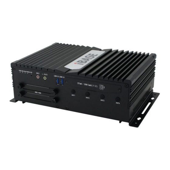
Page 14: Overview
1.6 Overview Front View No. Name Name LED Indicators USB 3.0 Receptacles Reset Button CFast / SIM Card Slot Door Secondary Microphone Input Antenna Holes Secondary Line-out SSD Drive Bays MPT-7000V User Manual... - Page 15 General Information Rear View No. Name Name GPIO Connector DC Input Connector LAN Ports with LED Indicators UPS Battery / DC 12V Output DVI-D Port COM3 / CAN (Optional) USB 2.0 Ports VGA Port First Microphone Input COM1 & COM2 Ports First Line-out Expansion Card Slot Oblique View...
-
Page 16: Device Dimensions
1.7 Device Dimensions Unit: mm 1.8 Fuse Dimensions ® ® Littlefuse TAC ATO Style Blade 15A, 58V DC MPT-7000V User Manual... -
Page 17: Chapter 2 Hardware Configuration
Chapter 2 Hardware Configuration The information provided in this chapter includes: • Essential installations • Information and locations of connectors... -
Page 18: Essential Installations
2.1 Essential Installations 2.1.1 Memory Installation If you need to replace or install the modules, perform the following steps: Loosen the following 4 screws to pull out the SSD trays. Turn your MPT-7000V upside down. Remove the following 4 screws to open the front I/O cover. - Page 19 Hardware Configuration Locate the memory slot and align the keys of the memory module with that on the memory slot. Insert the module slantwise and gently push the module straight down until the clips of the slot close to hold the module in place when the mdoule touches the bottom of the slot.
-
Page 20: Storage Installation
2.1.2 Storage Installation You can use either SSD or M.2 SATA card, or use both for storage. For SSD or M.2 SATA card replacement or installation, follow the instructions below. Installation for 2.5” SSD Release 2 screws to pull out an SSD tray (4 screws for 2 trays). Put your 2.5”... - Page 21 Hardware Configuration Installation for M.2 SATA Card Release the following 4 screws to pull out the SSD trays. Turn your device upside down. Remove 4 screws to remove the front I/O cover. Remove the following 8 screws to open the whole bottom cover. MPT-7000V User Manual...
- Page 22 Install the M.2 SATA card . a.) Take out the heatsink by releasing 4 screws and remove the brass standoff. b.) Align the key of the M.2 card to the M.2 interface, and insert the card slantwise. c.) Push the M.2 card down and fix the card with the brass standoff you just released.
-
Page 23: Cfast & Micro-Sim Card Installation
Hardware Configuration 2.1.3 CFast & Micro-SIM Card Installation Remove 2 screws as shown below to open the CFast & Micro-SIM card slot door. For CFast card, insert the card as below. To remove the CFast card, push the card again. For micro-SIM card, insert the card to one of the micro-SIM card slot with the chip up and push the card by using your fingernail or a corner of the CFast &... -
Page 24: Mini-Pcie & M.2 Network Cards Installation
2.1.4 Mini-PCIe & M.2 Network Cards Installation Before installation, firstly pay attention to the interrelation among the micro-SIM card slots, mini-PCIe slot, and M.2 slot as below. SIM Card Slot For mini-PCIe card installation, release the following 6 screws to half open the bottom cover after you remove the front I/O cover. -
Page 25: Wifi / 3G / 4G Antenna Installation
Hardware Configuration Locate the mini-PCIe slot, align the key of the mini-PCIe card to the interface, and insert the card slantwise. (Insert the M.2 network card in the same way.) Push the mini-PCIe card down, fix it with the supplied 2 flat head screws for full-sized card and with one screw for half-sized card. -
Page 26: Pcie (X16) Expansion Card Installation
2.1.6 PCIe (x16) Expansion Card Installation Remove the following 6 screws to half open the bottom cover after you remove the front I/O cover. Remove 2 screws on the rear I/O cover to take out the PCIe expansion bracket. Then remove a screw to separate the PCIe expansion bracket and its shield. - Page 27 Hardware Configuration Install the PCIe (x16) expansion card and fix the card to the bracket by tightening the screw as below. Screw PCIe Expansion Card Install the bracket with the card back to the device and tighten 2 screws on the rear I/O cover to fix the bracket.
-
Page 28: Mounting Brackets Installation
2.1.7 Mounting Brackets Installation Note: Before mounting the system on wall, ensure that you are following all applicable building and electric codes. Requirements When mounting, ensure that you have enough room for power and signal cable routing. And have good ventilation for power adapter. The method of mounting must be able to support weight of the MPT-7000V plus the suspend weight of all the cables to be attached to the system. - Page 29 Hardware Configuration Installation instructions: Turn your MPT-7000V upside down, attach the mounting brackets to MPT-7000V, and secure with the supplied 4 screws as below. Prepare at least 4 screws (M3, 6 mm) to mount MPT-7000V on wall . 4 screws You can install MPT-7000V on plastic (LCD monitor), wood, drywall surface over studs, or a solid concrete or metal plane directly.
-
Page 30: Pinout For Com Ports, Power Input & Gpio Connectors
2.1.8 Pinout for COM Ports, Power Input & GPIO Connectors • COM1 RS232/422/485 Port Assignment Assignment DCD, Data carrier detect DSR, Data set ready RXD, Receive data RTS, Request to send TXD, Transmit data CTS, Clear to send DTR, Data terminal ready RI, Ring indicator Ground Assignment... - Page 31 Hardware Configuration • DC Power 9 ~ 36V Input Connector (Terminal Block) Assigment Assigment Ignition Ground DC-Input • UPS Battery / DC Power 12V Output Connector (ATX Jack) Assigment Assigment Ground Ground 12V Out • GPIO Connector (terminal block) Assignment Assignment Ground DIO4...
-
Page 32: Setting The Jumpers
2.2 Setting the Jumpers Set up and configure your device by using jumpers for various settings and features according to your needs and applications. Contact your supplier if you have doubts about the best configuration for your use. 2.2.1 How to Set Jumpers Jumpers are short-length conductors consisting of several metal pins with a non-conductive base mounted on the circuit board. -
Page 33: Jumper & Connector Locations On Motherboard
Hardware Configuration 2.3 Jumper & Connector Locations on Motherboard Motherboard: MBT-7001V COM1 COM4 COM2 COM3 72 71 PCIE1 72 71 PCIE2 J16 J18 Battery CN10 CN13 CN14 CN11 CN12 CN15 CN16 MBT-7001V - top MPT-7000V User Manual... - Page 34 Intel ® Gen. Core™ i7-6600U MBT-7001V - bottom MPT-7000V User Manual...
-
Page 35: Jumpers Quick Reference
Hardware Configuration 2.4 Jumpers Quick Reference Function Connector Name Page COM1 & COM2 Voltage Selection JP1, JP2 ME Register Clearance CMOS Data Clearance Flash Descriptor Security Override Selection 2.4.1 COM1 & COM2 Voltage Selection (JP1, JP2) (for COM1) (for COM2) Function Pin closed Illustration... -
Page 36: Me Register Clearance (J12)
2.4.2 ME Register Clearance (J12) Function Pin closed Illustration Normal (default) Clear ME Register 2.4.3 CMOS Data Clearance (J14) Function Pin closed Illustration Normal (default) Clear CMOS MPT-7000V User Manual... -
Page 37: Flash Descriptor Security Override Selection (J15)
Hardware Configuration 2.4.4 Flash Descriptor Security Override Selection (J15) Function Pin closed Illustration No override Open (default) Override Close MPT-7000V User Manual... -
Page 38: Connectors Quick Reference
2.5 Connectors Quick Reference Function Connector Name Page PCIe (x4) Slot PCIE1 DC Power Input 12V Connector PCIE2 COM Port COM1, COM2, COM3, COM4 Digital I/O Connector DVI-D Port CN6 (system rear), Audio Jacks CN15, CN16 (system front) SATA III Connector CN7, CN8 CFast Connector CN10... -
Page 39: Pcie (X4) Slot (Pcie1)
Hardware Configuration Function Connector Name Page LED1 (for storage, white), LED2 (for WWAN, amber) LED3 (for WLAN, blue) LED Indicators LED4 (for MB Power, green) LED5 (for LAN, green) LED6 (for LAN, green) Power Board +12V Connector (Reserved) Power Connector (Reserved) Motherboard Power Button Connector Factory Use Only... -
Page 40: Com Port (Com1, Com2, Com3, Com4)
2.5.3 COM Port (COM1, COM2, COM3, COM4) COM1 COM4 COM3 COM2 Assignment Assignment Ground 2.5.4 Digital I/O Connector (CN1) Assignment Assignment Ground DIO4 DIO1 DIO5 DIO2 DIO6 DIO3 Ground MPT-7000V User Manual... -
Page 41: Dvi-D Port (Cn2)
Hardware Configuration 2.5.5 DVI-D Port (CN2) 2.5.6 Audio Jack (CN6, CN15, CN16) 2.5.7 SATA III Connector (CN7, CN8) MPT-7000V User Manual... -
Page 42: Cfast Connector (Cn10)
2.5.8 CFast Connector (CN10) 2.5.9 USB 3.0 Ports (CN11, CN12) 2.5.10 SIM Card Slot (CN13, CN14) CN13 is interrelated with the mini-PCIe slot J20. CN14 is interrelated with the M.2 slot J17. MPT-7000V User Manual... -
Page 43: Gbe Lan Ports (Cn3, Cn4)
Hardware Configuration 2.5.11 GbE LAN Ports (CN3, CN4) 2.5.12 USB 2.0 Ports (CN5) 2.5.13 SATA HDD Power Connector (J4, J21) J21: Assignment Assignment Ground Ground +12V MPT-7000V User Manual... -
Page 44: Crt Connector (J5)
2.5.14 CRT Connector (J5) Assignment Assignment Green Ground Blue DDCDATA Ground HSYNC Ground VSYNC Ground DDCCLK Ground 2.5.15 M.2 M2280 SATA Interface (J6) MPT-7000V User Manual... -
Page 45: E2230 Usb2.0 / Pcie (X1) Interface (J8)
Hardware Configuration 2.5.16 M.2 E2230 USB2.0 / PCIe (x1) Interface (J8) 2.5.17 DDR4 SO-DIMM Socket (J9, J10) MPT-7000V User Manual... -
Page 46: Future Connector For Can Module Connection (J11)
2.5.18 Future Connector for CAN Module Connection (J11) Assignment Assignment Ground USB- COM6_TX USB+ COM6_RX Ground 2.5.19 M.2 B3042 USB2.0 Interface (J17) J17 is interrelated with the SIM card slot CN14. MPT-7000V User Manual... -
Page 47: Half-Size Mini-Pcie Usb2.0 Connector (J19)
Hardware Configuration 2.5.20 Half-Size Mini-PCIe USB2.0 Connector (J19) 2.5.21 Full-Size Mini-PCIe USB2.0 / PCIe (x1) Connector (J20) J20 is interrelated with the SIM card slot CN13. 2.5.22 Reset Button (SW2) MPT-7000V User Manual... -
Page 48: Digital Io Pull High To +5V Switch (Sw1)
2.5.23 Digital IO Pull High to +5V Switch (SW1) Switch to ON to pull high to 5V. Assignment Assignment DIO1 DIO2 DIO3 DIO4 DIO5 DIO6 MPT-7000V User Manual... -
Page 49: Chapter 3 Driver Installation
Chapter 3 Driver Installation The information provided in this chapter includes: • ® Intel Chipset Software Installation Utility • VGA Driver Installation • HD Audio Driver Installation • LAN Driver Installation • ® Intel Management Engine Driver Installation • USB 3.0 Driver Installation... -
Page 50: Introduction
3.1 Introduction This section describes the installation procedures for software drivers. The software drivers are in a disk enclosed with the product package. If you find anything missing, please contact the distributor where you made the purchase. Note: After installing your Windows operating system, you must install the ®... - Page 51 Driver Installation Click Intel(R) Chipset Software Installation Utility. ® When the Welcome screen to the Intel Chipset Device Software appears, click Next to continue. Click Yes to accept the software license agreement and proceed with the installation process. On the Readme File Information screen, click Next for installation. The driver has been completely installed.
-
Page 52: Vga Driver Installation
3.3 VGA Driver Installation Insert the disk enclosed in the package. Click Intel and then Intel(R) Skylake-U Chipset Drivers. Click Intel(R) HD Graphics Driver. MPT-7000V User Manual... - Page 53 Driver Installation When the Welcome screen appears, click Next to continue. Click Yes to agree with the license agreement and then click Install for installation. The driver has been completely installed. You are suggested to restart the computer for changes to take effect. MPT-7000V User Manual...
-
Page 54: Hd Audio Driver Installation
3.4 HD Audio Driver Installation Insert the disk enclosed in the package. Click Intel and then Intel(R) Skylate-U Chipset Drivers. Click Realtek High Definition Audio Driver. MPT-7000V User Manual... - Page 55 Driver Installation On the Welcome screen of the InstallShield Wizard, click Next for installation. The driver has been completely installed. You are suggested to restart the computer for changes to take effect. MPT-7000V User Manual...
-
Page 56: Lan Driver Installation
3.5 LAN Driver Installation Insert the disk enclosed in the package with the product. Click LAN Card and then Intel(R) Skylake-U Chipset Drivers Click Intel(R) PRO LAN Network Drivers.. MPT-7000V User Manual... - Page 57 Driver Installation ® On the screen of Intel Network Connections, click Install Drivers and Software.. When the Welcome screen appears, click Next to continue. Accept the license agreement and click Next to continue. MPT-7000V User Manual...
- Page 58 Tick the checkbox for Drivers to select the related drivers and click Next. When the wizard is ready for installation, click Install. The driver has been completely installed. You are suggested to restart the computer for changes to take effect. MPT-7000V User Manual...
-
Page 59: Intel Management Engine Driver Installation
Driver Installation ® 3.6 Intel Management Engine Driver Installation Insert the disk enclosed in the package. Click Intel and then Intel(R) Skylake-U Chipset Drivers. Click Intel(R) ME 11.x Drivers. MPT-7000V User Manual... - Page 60 When the Welcome screen appears, click Next to continue. Accept the licence agreement and click Next until the installation starts. The driver has been completely installed. You are suggested to restart the computer for changes to take effect. MPT-7000V User Manual...
-
Page 61: Usb 3.0 Driver Installation
Driver Installation 3.7 USB 3.0 Driver Installation Insert the disk enclosed in the package. Click Intel and then Intel(R) Skylake-U Chipset Drivers. Click Intel(R) USB 3.0 Drivers. MPT-7000V User Manual... - Page 62 When the Welcome screen appears, click Next to continue. Accept the license agreement and click Next to continue. On the Readme File Information screen, click Next for installation. The driver has been completely installed. You are suggested to restart the computer for changes to take effect.
-
Page 63: Chapter 4 Bios Setup
Chapter 4 BIOS Setup This chapter the different settings available in the AMI describes BIOS that comes with the board. The topics covered in this chapter are as follows: • Main Settings • Advanced Settings • Security Settings • Boot Settings •... -
Page 64: Introduction
4.1 Introduction The BIOS (Basic Input/Output System) installed in the ROM of your computer system supports Intel® processors. The BIOS provides critical low-level support for standard devices such as disk drives, serial ports and parallel ports. It also provides password protection as well as special support for detailed fine-tuning of the chipset controlling the entire system. -
Page 65: Main Settings
BIOS Setup 4.3 Main Settings BIOS Setting Description System Date Sets the date. Use the <Tab> key to switch between the data elements. System Time Set the time. Use the <Tab> key to switch between the data elements. MPT-7000V User Manual... -
Page 66: Advanced Settings
4.4 Advanced Settings This section allows you to configure, improve your system and allows you to set up some system features according to your preference. MPT-7000V User Manual... -
Page 67: Acpi Settings
BIOS Setup 4.4.1 ACPI Settings BIOS Setting Description Enable Hibernation Enables or disables the System ability to Hibernate (OS/S4 Sleep State). This option may not be effective with some OS. MPT-7000V User Manual... -
Page 68: Power Board Configuration
4.4.2 Power Board Configuration BIOS Setting Description Power Board Delay Allows to set the delay timer for turning on or Control off the power board. Power On Delay Sets the power-on-delay timer for minutes / (minutes) / (seconds) seconds. Power Off Delay Sets the power-off-delay timer for minutes / (minutes) / (seconds) seconds. -
Page 69: Super Io Configuration
BIOS Setup 4.4.3 Super IO Configuration BIOS Setting Description Serial Port Configuration Sets parameters of serial ports. You can enable / disable the serial port and select an optimal settings for the Super IO device. COM5 is for internal use only. COM6 sigals come from the on-board connector J11, and is reserved for future use to connect to CAN module. - Page 70 4.4.3.1. Serial Port 1 Configuration BIOS Setting Description Serial Port Enables / Disables the serial port (COM). Change Settings Selects an optimal settings for the Super I/O device. F81866 Serial Port1 Changes the mode of serial port. Mode Seelct MPT-7000V User Manual...
- Page 71 BIOS Setup 4.4.3.2. Serial Port 2 Configuration BIOS Setting Description Serial Port Enables / Disables the serial port (COM). Change Settings Selects an optimal settings for the Super I/O device. MPT-7000V User Manual...
- Page 72 4.4.3.3. Serial Port 3 Configuration BIOS Setting Description Serial Port Enables / Disables the serial port (COM). Change Settings Selects an optimal settings for the Super I/O device. MPT-7000V User Manual...
- Page 73 BIOS Setup 4.4.3.4. Serial Port 4 Configuration BIOS Setting Description Serial Port Enables / Disables the serial port (COM). Change Settings Selects an optimal settings for the Super I/O device. MPT-7000V User Manual...
- Page 74 4.4.3.5. Serial Port 5 Configuration 4.4.3.6. Serial Port 6 Configuration BIOS Setting Description Serial Port Enables / Disables the serial port (COM). Change Settings Selects an optimal settings for the Super I/O device. Device Mode Changes the mode of serial port. MPT-7000V User Manual...
-
Page 75: Hardware Monitor
BIOS Setup 4.4.4 Hardware Monitor BIOS Setting Description ACPI Shutdown This field enables or disables the Shutdown Temperature Temperature Options: Disabled (default). 70 °C, 80 °C, 90 °C Temperatures / Voltages These fields are the parameters of the hardware monitoring function feature of the motherboard. -
Page 76: Nvme Configuration
4.4.5 NVMe Configuration 4.4.6 USB Configuration BIOS Setting Description Legacy USB Support Enables / Disables Legacy USB support. • Auto disables legacy support if there is no USB device connected. • Disable keeps USB devices available only for EFI applications. MPT-7000V User Manual... - Page 77 BIOS Setup BIOS Setting Description XHCI Hand-pff This is a workaround for OSes without XHCI hand-off support. The XHCI ownership change should be claimed by XHCI driver. USB Mass Storage Driver Enables / Disables USB mass storage driver Support support. USB Transfer time-out Sets the time-out value 1, 5, 10 or 20 sec(s) for Control, Bulk, and Interrupt transfers.
-
Page 78: Cpu Configuration
4.4.7 CPU Configuration BIOS Setting Description Intel(R) Speed Shift Enables / Disables the support for Intel(R) Technology Speed Shift Technology. If enabled, it will expose the CPPC v2 interface to allow for hardware controlled P states. Intel(R) SpeedStep(tm) Enables / Disables to support more than two frequency ranges. -
Page 79: Sata Configuration
BIOS Setup 4.4.8 SATA Configuration BIOS Setting Description SATA Controller(s) Enables / Disables SATA devices. SATA Mode Selection Selects AHCI / RAID Mode. SATA Controller Speed Indicates the maximum speed that the SATA controller supports. Serial ATA Port 0/1/2 Enables / Disables Serial Port 0/1/2. HotPlug Designates the SATA port as hot pluggable. -
Page 80: Csm Configuration
4.4.9 CSM Configuration BIOS Setting Description Network Controls the execution of UEFI and Legacy PXE OpROM. MPT-7000V User Manual... -
Page 81: Security Settings
BIOS Setup 4.5 Security Settings BIOS Setting Description Administrator Password Sets an administrator password for the setup utility. User Password Sets a user password. MPT-7000V User Manual... -
Page 82: Boot Settings
4.6 Boot Settings BIOS Setting Description Setup Prompt Timeout Number of seconds to wait for setup activation key. 65535 (0xFFFF) means indefinite waiting. Bootup NumLock State Selects the keyboard NumLock state. Quiet Boot Enables / Disables Quiet Boot option. Boot Mode Select Selects the boot mode as Legacy or UEFI. -
Page 83: Save & Exit Settings
BIOS Setup 4.7 Save & Exit Settings BIOS Setting Description Save Changes and Reset Resets the system after saving the changes. Discard Changes and Resets system setup without saving any Reset changes. Restore Defaults Restores the user defaults to all the setup options. -
Page 84: Appendix
Appendix This section provides the mapping addresses of peripheral devices and the sample code of watchdog timer configuration. • I/O Port Address Map • Interrupt Request Lines (IRQ) • Watchdog Timer Configuration • Software Development Kit for WDT.DLL... -
Page 85: I/O Port Address Map
Appendix A. I/O Port Address Map Each peripheral device in the system is assigned a set of I/O port addresses which also becomes the identity of the device. The following table lists the I/O port addresses used. Address Device Description 070h –... -
Page 86: Watchdog Timer Configuration
C. Watchdog Timer Configuration The Watchdog Timer (WDT) is used to generate a variety of output signals after a user programmable count. The WDT is suitable for the use in the prevention of system lock-up, such as when software becomes trapped in a deadlock. - Page 87 Appendix //--------------------------------------------------------------------------- void EnableWDT(int interval) unsigned char bBuf; bBuf = Get_F81866_Reg(0x2B); bBuf &= (~0x20); Set_F81866_Reg(0x2B, bBuf); //Enable WDTO Set_F81866_LD(0x07); //switch to logic device 7 Set_F81866_Reg(0x30, 0x01); //enable timer bBuf = Get_F81866_Reg(0xF5); bBuf &= (~0x0F); bBuf |= 0x52; Set_F81866_Reg(0xF5, bBuf); //count mode is second Set_F81866_Reg(0xF6, interval);...
- Page 88 //--------------------------------------------------------------------------- // THIS CODE AND INFORMATION IS PROVIDED "AS IS" WITHOUT WARRANTY OF ANY // KIND, EITHER EXPRESSED OR IMPLIED, INCLUDING BUT NOT LIMITED TO THE // IMPLIED WARRANTIES OF MERCHANTABILITY AND/OR FITNESS FOR A PARTICULAR // PURPOSE. //--------------------------------------------------------------------------- #include "F81866.H" #include <dos.h>...
- Page 89 Appendix //--------------------------------------------------------------------------- void Set_F81866_Reg( unsigned char REG, unsigned char DATA) Unlock_F81866(); outportb(F81866_INDEX_PORT, REG); outportb(F81866_DATA_PORT, DATA); Lock_F81866(); //--------------------------------------------------------------------------- unsigned char Get_F81866_Reg(unsigned char REG) unsigned char Result; Unlock_F81866(); outportb(F81866_INDEX_PORT, REG); Result = inportb(F81866_DATA_PORT); Lock_F81866(); return Result; //--------------------------------------------------------------------------- //--------------------------------------------------------------------------- // THIS CODE AND INFORMATION IS PROVIDED "AS IS" WITHOUT WARRANTY OF ANY // KIND, EITHER EXPRESSED OR IMPLIED, INCLUDING BUT NOT LIMITED TO THE // IMPLIED WARRANTIES OF MERCHANTABILITY AND/OR FITNESS FOR A PARTICULAR // PURPOSE.
-
Page 90: Software Development Kit For Wdt.dll
D. Software Development Kit for WDT.DLL 1. OS Supported Windows XP (32-bit / 64-bit) or above Driver Installation ⚫ For 32-bit environment: Step 1: Copy the file KMUI32_1K.SYS to <%WINDIR%>\SYSTEM32\DRIVERS. Step 2: The following parameters must be written to your registry. HKLM,"System\CurrentControlSet\Services\KMUI32_1K","ErrorCo ntrol",%REG_DWORD%,0x00000001 HKLM,"System\CurrentControlSet\Services\... - Page 91 Appendix ⚫ For 64-bit environment: Step 1: Copy “KMUI64_1K.SYS” file to <%WINDIR%>\SYSTEM32\DRIVERS Step 2: The following parameters must be written to your registry. HKLM,"System\CurrentControlSet\Services\KMUI64_1K","ErrorCo ntrol",%REG_DWORD%,0x00000001 HKLM,"System\CurrentControlSet\Services\ KMUI64_1K","Type",%REG_DWORD%,0x00000001 HKLM,"System\CurrentControlSet\Services\ KMUI64_1K","Start",%REG_DWORD%,0x00000000 HKLM,"System\CurrentControlSet\Services\ KMUI64_1K","DisplayName",%REG_SZ%,"KMUI64_1K" Step 3: Restart the system. Note: Do not install both of the 32-bit and 64-bit drivers on an operating system.
- Page 92 Exportion from IB_WDT.DLL / IB_WDT.64.DLL extern "C" __declspec(dllexport) int __stdcall InstallDriver(void); extern "C" __declspec(dllexport) int __stdcall RemoveDriver(void); extern "C" __declspec(dllexport) char* __stdcall GetWDTInfo(void); extern "C" __declspec(dllexport) int __stdcall EnableWDT(int); extern "C" __declspec(dllexport) int __stdcall DisableWDT(int); extern "C" __declspec(dllexport) int __stdcall IsDioAvailable(int); extern "C"...
- Page 93 Appendix ⚫ Watchdog extern "C" __declspec(dllexport) char * __stdcall GetWDTInfo(void); Input : None Output : Return a string that describes the module information. extern "C" __declspec(dllexport) int __stdcall EnableWDT(int); Input : Timer interval, depending on the WDT chip Output : Always return “0” For further information, refer to the datasheet for WDT or contact your sales representative.
- Page 94 ⚫ Digital I/O extern "C" __declspec(dllexport) int __stdcall IsDioAvailable(int); Input : Dummy data and will be ignored Output : Return 1 if the digital I/O is available, otherwise return 0. extern "C" __declspec(dllexport) int __stdcall SetDioInputMask(int); Input: : Hardware parameter for digital I/O input function call. For example, the 6 GPIO functions: GPIO_0 to GPIO_2 are mapped as the input functions, and GPIO_4 to GPIO_6 are mapped as the output functions.
- Page 95 Appendix SetDioInputMask: if ((*lpIsDioAvailable)(0)) int DioInput; printf(" Test for digital IO ..\n"); //Please check digital IO setting in BIOS setup utility //Here example as follow: // Digital GPIO [1..3] = Input // Digital GPIO [4..6] = Output //set hardware information for GPIO chip //bit 0..2 : input for GPIO_0 to GPIO_2 //bit 4..6 : output for GPIO_4 to GPIO_6 (*lpSetDioInputMask)(0x07);...
-
Page 96: Motherboard Mcu Isp Specifications
E. Motherboard MCU ISP Specifications 1. Description Security MCU provides following functionality ⚫ Getting Firmware Version Software can get the firmware version, MCU provides commands to get current major Version, minor version and build version. ⚫ Setting Power-On-Delay Timer MCU provides command to set power on delay timer, when arrived the setting time, MCU will send power button to let the system power ⚫... - Page 97 Appendix ⚫ Setting CB UVP Voltage MCU provides command to set under voltage protection of cat battery, when car battery voltage is lower than CB UVP setting value, MCU will check the voltage of UPS battery whether change power source to UPS battery or not. ⚫...
- Page 98 ⚫ Setting PB Voltage Offset MCU provides command to set UPS battery voltage offset. It can adjust this voltage disparity between actual measurement and detected form MCU. ⚫ Getting status MCU provides command to get current status which includes the power on delay timer setting, power off delay timer setting, low delay setting value, DC off timer value, temperature protect setting value, voltage protect setting value, Car battery &...
- Page 99 Appendix Protocol ⚫ Signal transmit format Bandwidth Baud rate: 19200 bps Data Format Parity: No Parity 1 start bit 8 data bits 1 stop bit ⚫ Packet Format Header Size Command Data 0 – 64 bytes 2 bytes 1 byte 1 byte 2 bytes Header bytes indicate start of the packet.
- Page 100 ⚫ Communications flow Communication between PC and Security MCU utilizes Master-Slave model, where PC is a master, and Security MCU is a slave. Master sends requests to the slave, and slave has to reply to them. Slave acts like a passive device and cannot send any requests to the master.
- Page 101 Appendix ⚫ Setting Power-On Delay Timer Parameter: SET_POWER_ON_DELAY_TIMER Sets power on delay timer. Request: Header Size Command Data0 Data1 0xFF 0x02 SET_POWER_ON_DELAY_TIME 0xEE (mins) (secs) Reply Header Size Command Data 0xFF 0x00 SET_POWER_ON_DELAY_TIM None 0xEE ⚫ Setting Power-Off Delay Timer Parameter: SET_POWER_OFF_DELAY_TIMER Sets power off delay timer.
- Page 102 Reply: Header Size Command Data 0xFF 0x04 GET_STATUS Status 0xEE structure BSL Version Structure Field Type Description Power on delay timer Word Byte4+ Byte5 Power off delay timer Word Byte6+ Byte7 MPT-7000V User Manual...
Need help?
Do you have a question about the MPT-7000VSM and is the answer not in the manual?
Questions and answers