
Related Manuals for Airflow Duplexvent Flexi DV650


Summary of Contents for Airflow Duplexvent Flexi DV650
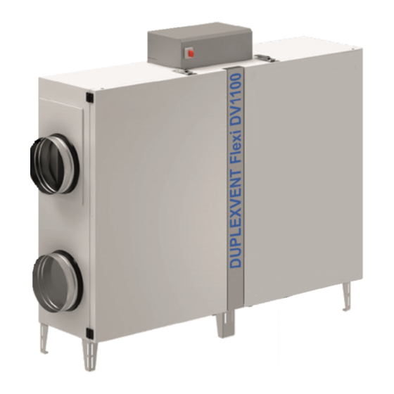
- Page 1 Installation, use and maintenance manual Duplexvent Flexi DV650, 1100,1600, 2600, 3600 Installation, use and maintenance manual...
- Page 2 Dear customer, Thank you for choosing our product and we hope that you will be fully satisfied. This manual contains all necessary instructions, information, hints and recommendations for safe and correct equipment installation and commissioning. Please read the manual carefully and follow the instructions contained herein.
-
Page 3: Table Of Contents
C o n t e n t s Safety instructions ................5 2.1. General safety ..................5 2.2. Operational safety ................. 5 Storage and transport ............... 5 Description ..................6 4.1. General ....................6 4.2. Intended use ..................7 Installation ..................7 5.1. - Page 4 10. Failures and troubleshooting ............23 11. Repairs, spare parts ................ 24 12. Warranty ................... 24 13. Visual appendix - manuals ............. 25 13.1. Connecting the condensate drain line ..........25 13.2. Rotating the fan ................... 26 13.3. Fitting the filters ................... 27...
-
Page 5: Safety Instructions
S a f e t y i n s t r u c t i o n s 2.1. General safety Only adults sufficiently familiar with the operation and maintenance manual may operate the equipment. The user must not tamper with or modify any part of the equipment, particularly the power supply lines! ... -
Page 6: Description
The appliance may only be transported on handling blocks (included). During transportation the appliance must be protected against mechanical damage and water penetration and all openings must be covered with protective covers. During transportation the appliance must be secured against falling. The mode of transport must also eliminate any falls of the appliance or instances of the appliance getting loose. -
Page 7: Intended Use
4.2. Intended use DUPLEXVENT Flexi series ventilation units with heat recovery are intended for the comfort ventilation and possibly hot-air heating and cooling of flats and houses, small plants, workshops, schools, restaurants, cooking facilities and industrial halls with a basic environment. The use of the unit must be in compliance with the Regulation of the Commission (EU) 1253/2014. -
Page 8: Configuring Orientation Of The Unit
of the HVAC network ensures positive pressure in the supply section of the appliance against the extraction section 5.3. Configuring orientation of the unit The versatile design of sizes 650, 1100, 1600, 2600 and 3600 allows adjusting the direction of air flow through the appliance;... -
Page 9: Identification Of Ports
e2 (SUP) i2 (EHA) i1 (ETA) e1 (ODA) DUPLEXVENT Flexi unit where M2 is set as supply fan (M-SUP) 5.4. Identification of ports Identify and label individual ports using the pictures below (labels are included). Begin by identifying port e1 (ODA) - outdoor air inlet; continue toward the fan on the same (shorter) side of the unit with exhaust air outlet port i2 (EHA);... -
Page 10: Connecting The Hvac Duct
5.6. Connecting the HVAC duct Connect the HVAC duct following the design documentation. To prevent injuries caused by the fan wheel, an HVAC duct at least 2 metres long must always be connected to the unit. The duct must be fastened in such a way that it cannot be removed without tools. -
Page 11: Connecting The Condensate Drain Pipe
The unit must be secured against movement. Ceiling-suspended position: The appliance is suspended from anchors of sufficient load bearing capacity (provided by the building contractor) using four (sizes 650, 1100, 1600 and 2600), and six (size 3600) suspension eyes (included in delivery) with Ø... -
Page 12: Classification Of Air Filters
Connect a pipe or hose (not included; a standard washing machine hose is recommended) to the condensate outlet and shape it into a siphon trap with dimensions as shown in the picture. Appropriately secure the siphon trap shape and connect it to the sewer line. ... -
Page 13: Installing, Connecting And Filling Liquid Manometers
Especially make sure that the arrow showing the direction of air flow through the filter cassette can ● be seen from the side of the operator (the arrow is by the unit´s door) and that it is always pointing toward the heat recovery exchanger! The unit is supplied with filter cassette labels unattached. -
Page 14: Installing Hot Water Heating Coil
DUPLEXVENT Flexi 2600 Filter type Flow rate (m 1000 1500 2000 2500 2600 Initial pressure loss (Pa) EPM1 Final pressure loss (Pa) Initial pressure loss (Pa) EPM10 Final pressure loss (Pa) DUPLEXVENT Flexi 3600 Filter type Volume flow rate (m 1400 2100 2800... -
Page 15: Installing Mixing Valve Of Hot Water Air Heater
Electrical installation may be carried out only by a person having the required electrotechnical qualification. Installation scheme when using the RD regulation: brown Servo drive R-HW of the mixing valve LM24A-SR black Cable: 4Ox1,5 (Germany NYM-O 4x1,5) blue brown Temperature sensor TA placed behind the heating coil white Cable: SYKFY 2x2x0,5 (Germany JYSTY 2x2x0,6) green... -
Page 16: Installing Mixing Valve Of The Water Chiller
For the appliance to work properly and safely it is necessary to correctly connect a condensate drain line! Connect a tube or a hose to the condensate drain outlet (not supplied; we recommend using a conventional washing machine hose) and shape it into a trap. Install the trap in the mounting position (see the pictures below), with the trap size according to chapter 5.8. -
Page 17: Electrical Connection, Commissioning, Description Of Controls
E l e c t r i c a l c o n n e c t i o n , c o m m i s s i o n i n g , d e s c r i p t i o n o f c o n t r o l s ... -
Page 18: Required Qualifications Of Personnel As Per The Type Of Activity
The user must be able at any given time to provide evidence as to the qualifications of operators. If sufficient number of qualified operational and service staff are not available, those activities must be commissioned to a specialist company that will be responsible for the proper operation of the appliance. -
Page 19: Inspecting The Appliance
I n s p e c t i n g t h e a p p l i a n c e 8.1. Overview of inspections and measures to ensure compliance with hygiene requirements The appliance must be regularly inspected in the areas listed below: ... - Page 20 Required interval in calendar months Hyg. Measures to be Activity inspec- taken tion Check for impurities, damage Cleaning and repair and corrosion Check tightness between Repair exhaust and outdoor air Check condensate tray for impurities, corrosion and Cleaning and repair functionality Check for impurities and Cleaning and repair...
-
Page 21: Cleaning And Maintenance
C l e a n i n g a n d m a i n t e n a n c e 9.1. General During the maintenance of the appliance follow instructions from the previous chapters, observe the basic rules of safety at work and proceed in compliance with the working regulations and use suitable means of access to the HVAC equipment (ladders, mobile stepladders, platforms etc.). -
Page 22: Cleaning The Plastic Heat Recovery Exchanger
If the vacuum cleaning of impurities while the coil remains in its place does not suffice, disconnect it from the heating / cooling medium, remove it and clean it using a high-pressure cleaner. Proceed with care so as not to damage the coil. ... -
Page 23: Failures And Troubleshooting
1 0 . F a i l u r e s a n d t r o u b l e s h o o t i n g Failure Symptoms Possible causes Troubleshooting Connect to power supply (switch on Appliance will not Power supply is not connected primary circuit breakers) -
Page 24: Repairs, Spare Parts
All warranty and post-warranty repairs are performed by the supplier or an authorized service company. Service technicians have an updated list of spare parts; you can also contact the manufacturer/supplier. www.airflow.com The guide on disassembling the unit is published at in compliance with the Regulation of the Commission (EU) 1253/2014. -
Page 25: Visual Appendix - Manuals
1 3 . V i s u a l a p p e n d i x - m a n u a l s 13.1. Connecting the condensate drain line... -
Page 26: Rotating The Fan
13.2. Rotating the fan The option is available for the model DUPLEXVENT Flexi 1600 only. -
Page 27: Fitting The Filters
13.3. Fitting the filters...
Need help?
Do you have a question about the Duplexvent Flexi DV650 and is the answer not in the manual?
Questions and answers