Advertisement
Quick Links
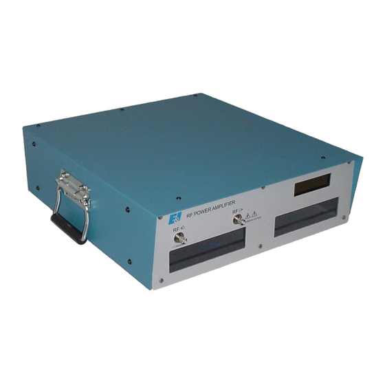
2100L
Broadband Power Amplifier
HIGH RF VOLTAGES MAY BE PRESENT AT THE OUTPUT OF THIS UNIT. All
operating personnel should use extreme caution in handling these voltages and be
thoroughly familiar with this manual.
Do not attempt to operate this unit prior to reading this manual.
The material contained in this document is the property of Electronics & Innovation Ltd., it is subject to
change without notice.
July 2012
Revision I
1
Advertisement

Related Manuals for E&I 2100L


Summary of Contents for E&I 2100L
- Page 1 2100L Broadband Power Amplifier HIGH RF VOLTAGES MAY BE PRESENT AT THE OUTPUT OF THIS UNIT. All operating personnel should use extreme caution in handling these voltages and be thoroughly familiar with this manual. Do not attempt to operate this unit prior to reading this manual.
-
Page 2: Table Of Contents
Warranty Electronics & Innovation Ltd., (hereafter E&I) warrants for the period of three years from the date of original delivery, each unit to be free of defects in materials and workmanship. For the period of 36 months E&I will, at its option, repair or replace defective parts so as to render the unit fully operational such that it performs according to the original specifications;... -
Page 3: Chapter 1 General Information
Chapter 1 Introduction The 2100L is a broadband solid state amplifier covering the frequency spectrum from 10 KHz to 12 MHz. It is rated at 100 watts of RF power with low harmonic and intermodulation distortion. Over 200 watts of saturated power can be produced with increased distortion products. -
Page 4: Chapter 2 Operation
Chapter 2 Operation 2.1 INTRODUCTION The 2100L RF amplifier is used to amplify the RF level of signal sources in the 10 KHz to 12 MHz range. No tuning or any other form of adjustment is required. The 2100L will work into any load impedance. Into a short circuit or infinite load at some phase angles it may protect itself at power greater than 80% rated power output. - Page 5 2.3.2 Front Panel Display The 2100L front panel has a passive LCD display designed for simplicity and ease of use. During initialization, the LCD shows the software revision. After the amplifier is initialized, the LCD indicates Forward Power, Reflected Power, and amplifier status (see figure 2.1).
- Page 6 If the fault persists, please contact Field Service. 2.3.3 RS 232 Interface The 2100L features a standard RS-232 serial interface suitable for connection to a PC or host system. The communication protocol is extremely simple to facilitate readback and control with readily available terminal programs such as Hyperterm.
-
Page 7: Technical Information
Chapter 3 Technical Description 3.1 GENERAL DESCRIPTION The 2100L is designed to amplify signals by 50 dB in the frequency band of 10 KHz to 12 MHz. The signal from the front panel BNC connector is fed via a length of 50 ohm coaxial cable into the input of the driver amplifier module. -
Page 8: Maintenance
The main power supply unit provides a 48 VDC 12 ampere source. It is a switch mode power supply unit. The output feeds the PA and the 24 Volt DC power supply regulator. This in turn provides power for the drive amplifier. The main power supply also has a 5 VDC output which feeds the control board. - Page 9 4.1 INTRODUCTION The E&I 2100L RF amplifier requires no periodic maintenance. The instrument is unconditionally stable and is fail-safe under all load conditions. Damage can only be externally caused by the incorrect selection of the AC supply voltage or by an input signal in excess of the specified 1 volt rms equivalent to a power level of 13dBm.
- Page 10 Set the sweep generator to the video sweep mode with the start frequency at 10 kHz and the sweep width to 12 MHz. Disconnect the 2100L from the set-up and connect the sweep/generator RF output directly to the 30 dB attenuator.
- Page 11 Return sweep/generator output level to full deflection. Rotate the step attenuator (CCW) so that the output is reduced by 50 dB. Reconnect the 2100L into the test set-up of Figure 4-1. Place the 2100L power switch to the "ON" position.
-
Page 12: Chapter 5 Safety
Connect Equipment shown Figure 4-2, then proceed as follows: Adjust the signal generator to a CW center frequency of 10 kHz, for an indicated output of 100 watts on the power meter. Using the spectrum analyzer, check that the level of the carrier harmonics is less than -25 dB with respect to the carrier while manually scanning the frequency band of 10 KHz to 12 MHz.
Need help?
Do you have a question about the 2100L and is the answer not in the manual?
Questions and answers