Advertisement
Quick Links
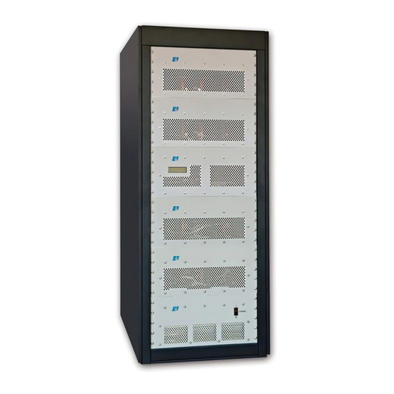
A 1000
Broadband Power Amplifier
HIGH RF VOLTAGES MAY BE PRESENT AT THE OUTPUT OF THIS UNIT. All
operating personnel should use extreme caution in handling these voltages and be
thoroughly familiar with this manual.
Do not attempt to operate this unit prior to reading this manual. Specifically
Chapter 5; SAFETY.
The material contained in this document is the property of Electronics & Innovation Ltd., it is subject to
change without notice.
September 2010
Revision A
1
Advertisement

Related Manuals for E&I A 1000


Summary of Contents for E&I A 1000
- Page 1 A 1000 Broadband Power Amplifier HIGH RF VOLTAGES MAY BE PRESENT AT THE OUTPUT OF THIS UNIT. All operating personnel should use extreme caution in handling these voltages and be thoroughly familiar with this manual. Do not attempt to operate this unit prior to reading this manual. Specifically Chapter 5;...
- Page 2 Warranty Electronics & Innovation Ltd., (hereafter E&I) warrants for the period of one year from the date of original delivery, each unit to be free of defects in materials and workmanship. For the period of 12 months E&I will, at its option, repair or replace defective parts so as to render the unit fully operational such that it performs according to the original specifications;...
- Page 3 Chapter 1 Introduction The A 1000 is a broadband solid state amplifier covering the frequency spectrum from 300 KHz to 35 MHz. It is rated at 1000 watts of RF power with low harmonic and intermodulation distortion. Over 1500 watts of saturated power can be produced with increased distortion products.
- Page 4 Table 1-1. SPECIFICATIONS FREQUENCY COVERAGE: 300 kHz to 35 MHz. GAIN: 60 dB min, ±1.5 variation. CLASS A LINEAR OUTPUT: Nominal 1000 watts. SATURATED RF POWER OUTPUT: 1500 Watts min INPUT IMPEDANCE 50 ohms, VSWR, 1.5:1 Maximum. OUTPUT IMPEDANCE: 50 ohms, VSWR, 2.5:1 Maximum Continuous operation into any load or STs STABILITY: source impedance.
- Page 5 2.2 RACK INSTALLATION This unit is 35.5 U high, 24” width, 30” Length. 2.2.1 Mains Voltage The unit runs of 208 3 phase VAC 47 – 63 Hz. 30 Amps max 2.3 OPERATION A fixed line cord is supplied to form a connection between the mains supply and the rear of the unit.
- Page 6 PSU fault (internal fault in the main switching power supply) In the event of a fault, the unit may be reset by cycling the power. In the case over an over temp fault, ensure that the air inlet and out let are not restricted. If the fault persists, please contact Field Service.
- Page 7 In the default state, the RS-232 port will echo the same information sent to the front panel LCD display, allowing a running datalog to be stored to disk using the capture feature of the terminal program. Single character commands can be sent to the amplifier to achieve the following: "1"...
- Page 8 There are three switch mode power supply modules that provide a 42 VDC 300 ampere source. Another provides 24 VDC outputs and provides 6.3 amps. The 24 Vdc power supply also has a 5 VDC output which feeds the control board. The material contained in this document is the property of Electronics &...
- Page 9 Chapter 4 Maintenance 4.1 INTRODUCTION The E&I A1000 RF amplifier requires no periodic maintenance. The instrument is unconditionally stable and is fail-safe under all load conditions. Damage can only be externally caused by the incorrect selection of the AC supply voltage or by an input signal in excess of the specified 1 volt rms equivalent to a power level of 13 dBm or a power level of 1 dBm for greater than one minute.
- Page 10 Performance limits quoted are for guidance only and should not be taken for guaranteed performance specifications unless they are also quoted in the Specification Section 1.2. 4.2 PERFORMANCE CHECKS To determine the amplifier’s performance carry out the following procedure. 4.2.1 Initial Check The following check can be made after repair and adjustments or whenever the condition of the unit is in question.
- Page 11 4.3.1 Measurement of Gain Equipment Required (or equivalent): Osilloscope - Tektronix T921 Sweep/Generator - HP8601A Signal Generator - Exact Model 7060 50 ohm Detector - Wavetek D151 Attenuator, 60 dB, 1000 Watts Bird Sweep Generator 300 KHz – 35 MHz Sweep Signal Input...
- Page 12 Adjust the output level of the sweep/generator for full vertical deflection on the oscilloscope face. Calibrate the scope face to show 3 dB in 1 dB steps by attenuating the sweep/generator in 1 dB. Return sweep/generator output level to full deflection. Rotate the step attenuator (CCW) so that the output is reduced by 60 dB.
- Page 13 Spectrum Analyzer. Attenuator (60dB) Coupler (60 dB) Connect the Equipment as shown in Figure 4-2, then proceed as follows: Adjust the signal generator to a CW center frequency of 300 kHz, for an indicated output of 1000 watts on the power meter. Using the spectrum analyzer, check that the level of the carrier harmonics is less than -22 dB with respect to the carrier while manually scanning the frequency band of 300 KHz to 35 MHz.
Need help?
Do you have a question about the A 1000 and is the answer not in the manual?
Questions and answers