Table of Contents
Advertisement
Quick Links
Trademarks
®
Auro
and OtoSys
registered in China, the United States and other countries. All other marks
are trademarks or registered trademarks of their respective holders.
Copyright Information
No part of this manual may be reproduced, stored in a retrieval system or
transmitted, in any form or by any means, electronic, mechanical,
photocopying, recording, or otherwise without the prior written permission of
Auro.
Disclaimer of Warranties and Limitation of Liabilities
All information, specifications and illustrations in this manual are based on
the latest information available at the time of printing.
Auro reserves the right to make changes at any time without notice. While
information of this manual has been carefully checked for accuracy, no
guarantee is given for the completeness and correctness of the contents,
including but not limited to the product specifications, functions, and
illustrations.
Auro will not be liable for any direct, special, incidental, indirect damages or
any economic consequential damages (including the loss of profits).
IMPORTANT
Before operating or maintaining this unit, please read this manual carefully,
paying extra attention to the safety warnings and precautions.
For Services and Support
www.aurodiag.com
support@aurodiag.com
For technical assistance in all other markets, please contact your local selling
agent.
®
are trademarks of Shenzhen HC Tech CO., Ltd.,
i
Advertisement
Table of Contents

Related Manuals for Aurodiag OtoSys IM600

Summary of Contents for Aurodiag OtoSys IM600
- Page 1 IMPORTANT Before operating or maintaining this unit, please read this manual carefully, paying extra attention to the safety warnings and precautions. For Services and Support www.aurodiag.com support@aurodiag.com For technical assistance in all other markets, please contact your local selling agent.
- Page 2 Safety Information For your own safety and the safety of others, and to prevent damage to the device and vehicles upon which it is used, it is important that the safety instructions presented throughout this manual be read and understood by all persons operating or coming into contact with the device.
- Page 3 Safety Instructions The safety messages herein cover situations Auro is aware of. Auro cannot know, evaluate or advise you as to all of the possible hazards. You must be certain that any condition or service procedure encountered does not jeopardize your personal safety. DANGER When an engine is operating, keep the service area WELL VENTILATED or attach a building exhaust removal system to the engine exhaust system.
- Page 4 Refer to the service manual for the vehicle being serviced and adhere to all diagnostic procedures and precautions. Failure to do so may result in personal injury or damage to the test equipment. To avoid damaging the test equipment or generating false data, make sure the vehicle battery is fully charged and the connection to the vehicle DLC is clean and secure.
-
Page 5: Table Of Contents
CONTENTS 1 USING THIS MANUAL ................. 1 ....................1 ONVENTIONS 2 GENERAL INTRODUCTION ................ 3 IM600 D ..............3 ISPLAY ABLET – W ..........7 LASH IRELESS IAGNOSTIC NTERFACE UP400 ......................10 ..................20 CCESSORIES 3 GETTING STARTED .................. 23 .................... - Page 6 9 SETTINGS ....................101 ......................101 ....................102 ANGUAGE ..................103 RINTING ETTING ................. 104 OTIFICATION ENTER ..................... 105 PDATE ......................107 BOUT ..................107 YSTEM ETTINGS 10 REMOTE DESK ..................109 11 DATA MANAGER ..................111 ....................111 PERATIONS 12 SHOP MANAGER ..................
-
Page 7: Using This Manual
Using this Manual This manual contains device usage instructions. Some illustrations shown in this manual may contain modules and optional equipment that are not included in your system. Conventions The following conventions are used. Bold Text Bold text is used to highlight selectable items such as buttons and menu options. - Page 8 Example: IMPORTANT Keep the cable away from heat, oil, sharp edges and moving parts. Replace damaged cables immediately. Hyperlink Hyperlinks, or links, that take you to other related articles, procedures, and illustrations are available in electronic documents. Blue italic text indicates a selectable hyperlink and blue underlined text indicates a website link or an email address link.
-
Page 9: General Introduction
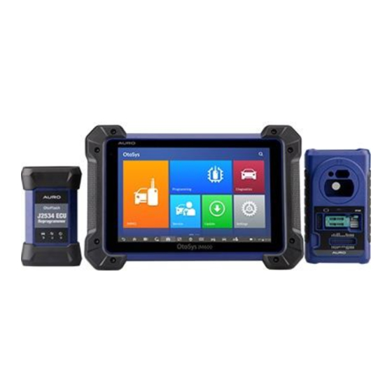
General Introduction Auro presents the OtoSys IM600 as the most advanced and smart key programming tool that combines the most powerful IMMO and programming functions with OE-level diagnostics and advanced service functions in one Android based 10.1-inch touchscreen tablet. With the included key programmer UP400 and OtoFlash ECU Reprogrammer,... - Page 10 Ambient Light Sensor – detects ambient brightness. Power LED – indicates battery level & charging or system status. Microphone The power LED displays green, yellow or red depending on power level and operating state. A. Green Illuminates green when the Display Tablet is charging and the battery level is above 90%.
- Page 11 Built-in Battery Loudspeaker Camera Lens Camera Flash Figure 2-3 Display Tablet Top View 10. DC Power Supply Input Port 11. Headphone Jack 12. USB Port 13. HDMI (high-definition multimedia interface) Port 14. USB Port 15. Mini USB Port 16. Lock/Power Button – turns the device on & off with long press, or locks the screen with short press.
- Page 12 External Power Supply The Display Tablet can be powered from a wall socket using the AC/DC power adapter. The AC/DC power supply also charges the internal battery pack. Technical Specifications Table 2-1 Specifications Item Description Operating System Android 4.4.2, KitKat Samsung Exynos hexa-core Processor (1.3GHz Processor Quad-core ARM Cortex-A7 + 1.7GHz Dual-core...
-
Page 13: Otoflash - Wireless Diagnostic Interface
Item Description Power 6.5 W Consumption Operating Temp. 0 to 50° C (32 to 122° F) Storage Temp. -20 to 60° C (-4 to 140° F) Dimensions ( 300 mm (11.81”) x 220 mm (8.66”) x 50 mm (1.97”) WxHxD Weight NW: 1.42 kg (3.13 lb.) GW: 8.655 kg (19.08 lb.) - Page 14 Functional Description Figure 2-4 OtoFlash Views Power Port – connects the device and the power source with the adapter. Vehicle Connector – connects the device to the vehicle’s DLC via a standard high density DB-26 MVCI – OBDII cable. USB Port Vehicle LED Connection LED Power LED...
- Page 15 Illuminates solid green when properly Green connected with the display tablet via the USB cable. Connection Illuminates solid blue when connected with the Blue display tablet via wireless (BT) connection. Illuminates solid green when powered on. Green Flashes red when system failure occurs. power illuminates amber...
-
Page 16: Up400
UP400 The UP400 is specially designed to read transponder data (including Mercedes Benz infrared smart key), clone and generate exclusive keys, read/write on-board EEPROM data, and read/write Freescale 9S12 MCUs. By working with diagnostic tool and PC that are both loaded with programmer software, the UP400 can read/write transponder data quickly and accurately. - Page 17 Mercedes Infrared Key Slot – holds the Mercedes infrared key. 10. Status LED – indicates the current operating status. 11. Locker – locks the EEPROM component transponder slot to ensure proper functioning. 12. EEPROM Component Transponder Slot – holds the EEPROM plug-in transponder or EEPROM socket.
- Page 18 Green and REMOTE_RX_C White APA104 – ECU Cable Table 2-5 Definitions of ECU Cable Color Definition correspond Note to DB26 VCC12V Black Green Orange CANL Blue CANH Brown BOOTM Yellow White APA105 – MCU Cable Table 2-6 Definitions of MCU Cable Color Definition Note...
- Page 19 Brown Gray Blue Orange Purple Yellow Green Shielded Black Twisted Shielded White Twisted APA106 – MC9S12 Cable Table 2-7 Definitions of MC9S12 Cable Pin correspond Color Definition Note to DB26 Black Green XCLKS Blue Yellow RESET Shielded Black Twisted Shielded White Twisted...
- Page 20 Cross-shaped Signal Pin The Cross-shaped signal pin is used to place MCU board, MCU spare cable or DIY signal cable to read or write MCU and ECU chips. IC Card Induction Area It is used to read and write IC card information. Vehicle Key Slot It is used to hold the vehicle key to read or write vehicle key information.
- Page 21 EEPROM Component Transponder Slot It is used to hold the EEPROM plug-in transponder or EEPROM socket. EEPROM Read/Write Transponder Coverage Chip Type Name Chip Type Name ATMEL AT24C01 ATMEL AT24C1024 ATMEL AT24C02 ATMEL AT24C128_1.8 ATMEL AT24C04 ATMEL AT24C256_1.8 ATMEL AT24C08 ATMEL AT24C512_1.8 ATMEL...
- Page 22 Chip Type Name Chip Type Name FAIRCHILD NM24C17UT ATMEL AT25640_1.8 MICROCHIP 85C72 ATMEL AT25128_1.8 MICROCHIP 85C82 ATMEL AT25256_1.8 MICROCHIP 85C92 M95010 PCF8582C M95020 PCF8594C M95040 PCF8598C M95080 ATMEL AT25010 M95160 ATMEL AT25020 M95320 ATMEL AT25040 M95640 ATMEL AT25080 M95128 ATMEL AT25160 M95256 ATMEL...
- Page 23 Chip Type Name Chip Type Name CATALYST CAT25C02 MICROCHIP 93C56 CATALYST CAT25C04 MICROCHIP 93C66A CATALYST CAT25C08 MICROCHIP 93C66 CATALYST CAT25C16 MICROCHIP 93C76A CATALYST CAT25C32 MICROCHIP 93C76 CATALYST CAT25C64 MICROCHIP 93C86A CATALYST CAT25C128 MICROCHIP 93C86 CATALYST CAT25C256 ATMEL AT93C46A M35080 ATMEL AT93C46 XICOR X5043...
- Page 24 Chip Type Name Chip Type Name M93C86 TOSHIBA TC89102 M93S46 TOSHIBA TC89121 M93S56 TOSHIBA TC89122 M93S66 Xicor X24C44 ATMEL AT59C11 TMC93LC56 ATMEL AT59C22 TMC93LC57 ATMEL AT59C13 TMC93LC66 MSM16911 TMC93LC86 TMC93LC46 MCU/ECU Read/Write Transponder Coverage Chip Type Name FREESCALE MC9S12DG128 FREESCALE MC9S12DJ64 FREESCALE MC9S12DG256...
- Page 25 FREESCALE MC68HC11E9 INFINEON SAK-TC1766 INFINEON SAK-TC1793 INFINEON SAK-TC1796 INFINEON SAK-TC1797 Technical Specifications Table 2-9 Specifications Item Description Operating Temperature -10℃ ~ 85℃ (14℉ ~ 185℉) Storage Temperature -20℃ ~ 85℃ (-4℉ ~ 185℉) Port Mini USB, VGA_DB15 Input Voltage 5 VDC Operating Current <...
-
Page 26: Accessories Kit
Accessories Kit Main Cable The Main Cable connects the Display Tablet to the vehicle’s data link connector (DLC). Figure 2-6 Main Cable Other Included Accessories USB Cable Mini USB Cable Connects the Display Tablet to the PC or DC external power adapter. AC/DC Adapter (12V) Light Fuse 6*30mm (2pcs) - Page 27 APB101+APD101 EEPROM Adaptor + EEPROM Adaptor Shell APB102 MB IR Cable APB104 MCU_FQFP64 APB105 MCU_FQFP80 APB107 MCU_FQFP112 APB107 MCU_FQFP114 APB108 MCU_FQFP176 APA002 EEPROM Socket APA101 Signal Cable...
- Page 28 APA103 EEPROM Clamp APA104 ECU Cable APA105 MCU Cable APA106 MC9S12 Cable APA107 Connect Cable Quick Guide Device connection and software update instructions.
-
Page 29: Getting Started
Getting Started Ensure the tablet is sufficiently charged or is connected to the external power supply (see Power Sources on page 5). NOTE The images and illustrations depicted in this manual may differ from the actual ones. Powering Up Long press the Lock/Power button on the top right of the tablet to power on the unit. - Page 30 NOTE The tablet screen is locked by default when first powered on. It is recommended to lock the screen to protect the information in the system and reduce the power consumption. The touch screen navigation is menu driven enabling quick access to functions and features by tapping on options headings and answering dialog windows.
- Page 31 Button Name Description Accesses the organization system for saved Data Manager data files. See Data Manager on page 111 for details. Accesses Shop manager database to store workshop, customer information and vehicle Shop Manager test history. See Shop Manager on page 116 for details.
- Page 32 Button Name Description Brightness/ Adjust the brightness and volume of the tool. Volume OtoSys Returns to OtoSys Job Menu. Home Returns to VCI Manager screen. IMMO Returns to the IMMO screen. Shortcut Diagnostic Returns to the Diagnostic screen. Shortcut Service Returns to the Service screen.
-
Page 33: Powering Down
Enables/disables Airplane Mode when Airplane Mode pressed. Launches the Android System Settings System Settings screen when pressed. Powering Down All vehicle communications must be terminated before shutting down the Display Tablet. A warning message displays if you attempt to shut down the Display Tablet when it is communicating with the vehicle. -
Page 34: Immo
Remote Control Learning, Remote Control Add, etc. Establish Vehicle Communication The IMMO operations require connecting the OtoSys IM600 tablet to the test vehicle through the OtoFlash using the main cable and the included USB cable (2m). To establish proper vehicle communication to the tablet, you need to perform the following steps: Connect the OtoFlash to the vehicle’s DLC for both communication and... - Page 35 OBD II Vehicle Connection This type of connection only requires the main cable without any additional adapter. To connect to an OBD II vehicle Connect the main cable’s female adapter to the Vehicle Data Connector on the OtoFlash, and tighten the captive screws. Connect the cable’s 16-pin male adapter to the vehicle’s DLC, which is generally located under the vehicle dashboard.
- Page 36 To connect the cigarette lighter Plug the DC power connector of the cigarette lighter into the DC power supply input port on the device. Connect the male connector of the cigarette lighter into the vehicle’s cigarette lighter receptacle. NOTE After the OtoFlash is successfully connected to the vehicle, the Power LED on the device illuminates, and a brief beep sound will be heard.
- Page 37 automatically starts scanning for available VCI devices around for BT pairing. The found devices are listed in the Setting section on the right side of the screen. NOTE If no VCI device is found, this may indicate that the signal strength of the transmitter is too weak to be detected.
-
Page 38: Getting Started
Check if the OtoFlash is powered on. In case of wireless connection, check if the network is configured correctly, or if the right device has been paired. If during the diagnosis process, communication is suddenly interrupted due to the loss of signal, check if there are any objects that causes signal interruption. - Page 39 Vehicle Menu Layout When the tablet is properly connected to the vehicle, the platform is ready to start vehicle diagnosis. Tap on the IMMO application button on the OtoSys IM600 Job Menu to access the Vehicle Menu. Figure 4-1 Sample Vehicle Menu Top Toolbar Buttons Manufacturer Buttons Top Toolbar Buttons...
-
Page 40: Vehicle Identification
Displays the stored test vehicle history records. This option provides you direct access to the previously History tested vehicle recorded during previous test sessions. See Vehicle History on page 117. Displays the USA vehicle menu. Europe Displays the European vehicle menu. Asia Displays the Asian vehicle menu. - Page 41 this application, and technicians can manually select the part information follow the onscreen instructions to display the function menu. Auto VIN Scan The OtoSys diagnostic system features the latest VIN-based Auto VIN Scan function to identify vehicles and it is applied to IMMO, Programming, Diagnostic and Service applications.
- Page 42 IMMO control unit information. Manual VIN Input For vehicles that not supporting the Auto VIN Scan function, you may manually enter the vehicle VIN. To perform Manual VIN Input Tap the IMMO application button from the OtoSys Job Menu. The Vehicle Menu displays.
-
Page 43: Navigation
The Vehicle Menu displays. Tap the manufacturer button of the test vehicle. Tap Automatic Selection and the VIN information will be automatically acquired. Follow the on-screen instruction to display the function screen. Manual Selection When the vehicle’s VIN is not automatically retrievable through the vehicle's ECU, or the specific VIN is unknown, the vehicle can be manually selected. - Page 44 IMMO Screen Layout Figure 4-4 Sample Mode Selection Screen The IMMO screens typically include four sections. Operation Toolbar Status Information Bar Main Section Functional Buttons Operation Toolbar The Operation Toolbar contains a number of buttons such as print and save. The table below provides a brief description of the operations.
- Page 45 Button Name Description Prints a copy of the displayed data. See Printing Print Setting for additional information on page 103. Help Displays operational instructions or tips. Tap this button to open a sub menu, tap Save This Page to take a screenshot. Save All saved data is stored in the Data Manager application for later reviews.
- Page 46 Tap the Data Logging button. The button displays blue during the active recording process. Tap the Data Logging button again to end recording. A submission form will display for inputting of report information. Tap the Send button to submit the report form via the Internet. A confirmation message displays when the report has been successfully sent.
-
Page 47: Immo
Confirmation Messages This type of messages usually displays as an “Information” screen to inform the user that a selected action cannot be reversed or when an action has been initiated and confirmation is needed to continue. When a user-response is not required to continue, the message displays briefly. - Page 48 After a mode is selected and the tablet establishes communication with the vehicle, the corresponding function menu or selection menu displays. Smart Mode The Smart Mode provides guided functions with step-by-step instructions. Once the test vehicle is identified, a vehicle profile will display, select Yes to continue.
- Page 49 Figure 4-6 Sample Check Key Status Screen Read the vehicle key status carefully and press OK to display the function menu. Figure 4-7 Sample Function Menu in Smart Mode The functions vary by IMMO parts, please follow the onscreen instructions to select the correct IMMO part.
- Page 50 Figure 4-8 Sample Key Learning Screen 1 When Read IMMO data completes, the tablet will prompt a “Do you need to make dealer key?” message, select Yes to confirm, or select NO to quit the operation. Figure 4-9 Sample Key Learning Screen 2 Follow the onscreen instruction to place a Blank Key in the UP400 key slot and press OK to continue.
- Page 51 Figure 4-10 Sample Key Learning Screen 5 Follow the onscreen instructions to insert the key to be learned into the vehicle ignition switch. Figure 4-11 Sample Key Learning Screen 6 10. When Key Learning is completed successfully, the following screen displays.
- Page 52 Figure 4-12 Sample Key Learning Screen 7 Expert Mode Expert Mode provides skilled technicians a convenient way to perform individual IMMO functions they need. All the function options in this mode are separated segments. If needed, technicians can only perform one segment function instead of a whole process provided in Smart Mode.
- Page 53 For Instrument CAN and Engine, the tool supports auto detect. Figure 4-14 Sample Auto Detect Screen Figure 4-15 Sample Function Screen Tap Auto Detect and the screen displays the functions menu. Read IMMO Data Select Read IMMO Data from the function menu. The tablet will start to read IMMO information.
- Page 54 Figure 4-16 Sample Read IMMO Data Screen After the IMMO data is read, technicians can perform other IMMO functions with the read data in Expert Mode. Learn Key Select Learn Key from the function menu. The tool will confirm whether the vehicle has Kessy, tap Yes or No according to the situation to continue.
- Page 55 Figure 4-18 Sample Learn Key Screen 1 Insert in sequence the keys that need to be learned into the vehicle. The Figure 4-19 Sample Learn Key Screen 2 keys should be changed at an interval of less than 5s. Once the keys are successfully learned, the screen displays the message “Key learning completed”, tap OK to exit.
- Page 56 Figure 4-20 Sample Learn Key Screen 3...
-
Page 57: Programming
Programming The Programming application requires connection between the tablet and the UP400, and no vehicle connection is required. This application can access the key chip, read, retrieve and write key information, as well as other key related functions. Programming Select the vehicle manufacturer in the vehicle menu, and then follow the onscreen instructions to select the instrument information to display the function menu. - Page 58 Figure 5-2 Sample Select Chip Type Screen The screen displays the types of EEPROM supported. Select the right type. Figure 5-3 Sample Chip Type Screen Select Read Operation on the next menu.
- Page 59 Figure 5-4 Sample Operations Menu The chip data screen displays. Select Save to save the data, or select Cancel to exit. Figure 5-5 Sample Read Operation Screen Type the file name and select Confirm, the chip data will be saved on the tablet.
- Page 60 Figure 5-6 Sample Save Data Screen Select Write Operation from the operations menu. The tablet will open the default folder, select the saved data and click Confirm to write it into a black chip. And a “Chip written successfully.” message displays. Figure 5-7 Sample Write Operation Screen Key Read &...
- Page 61 Figure 5-8 Sample Key Select Screen Once the key type is successfully detected, the screen displays the key Figure 5-9 Sample Key Type Screen type, tap OK to enter the operation interface. The screen displays the supported functions which usually include Read out key ID, Read out key information, Write page.
- Page 62 Figure 5-11 Sample Functions Screen Figure 5-10 Sample Key ID Screen Tap Read out key ID to read the key ID. Tap Read out key information to read the information.
- Page 63 Figure 5-12 Sample Read Out Key Information Screen Tap Write page data to write the data. Figure 5-13 Sample Write Page Data Screen Remote Detection Tap Remote Detection from the menu, the function menu displays.
- Page 64 Figure 5-14 Sample Remote Detection Function Screen Put the key into suitable area and press down any key button. The Figure 5-15 Sample Frequency Display Screen screen displays the frequency of the key. Tap Read out remote information to check the information.
- Page 65 Figure 5-16 Sample Remote Information Screen...
-
Page 66: Diagnostics
Diagnostics The Diagnostics application can retrieve ECU information, read & erase DTCs, and view live data. The Diagnostics application can access the electronic control unit (ECU) for various vehicle control systems, including engine, transmission, antilock brake system (ABS), airbag system (SRS). Diagnosis The Diagnostics application enables a data link to the electronic control system of the test vehicle for vehicle diagnosis via OBD II connection. - Page 67 Auto Scan The Auto Scan function performs a comprehensive scanning over all the ECUs in the vehicle to locate systems’ faults and retrieve DTCs. The sample operation interface of Auto Scan displays as below: Figure 6-1 Sample Auto Scan Operation Screen Navigation Bar Main Section Functional Buttons...
- Page 68 Fault(s) | #: Fault(s) indicates there is/are detected fault code(s) present; “#” indicates the number of the detected faults. Pass | No Fault: Indicates the system has passed the scanning process and no fault has been detected. Column 4 – to perform further diagnosis or testing on a specific system item, tap the button to the right of that item.
- Page 69 Figure 6-2 Sample Function Menu Screen The Function Menu options vary slightly for different vehicles. The function menu may include: ECU Information – provides the retrieved ECU information in detail. An information screen opens upon selection. Read Codes – displays detailed information of DTC records retrieved ...
- Page 70 To perform a diagnostic function Establish communication with the test vehicle. Identify the test vehicle by selecting from the menu options. Select the Diagnosis section. Locate the required system for testing by Auto Scan or through menu driven selections in Control Units. Select the desired diagnostic function from the Function Menu.
- Page 71 Read Codes This function retrieves and displays the DTCs from the vehicle’s control system. The Read Codes screen varies for each vehicle being tested. On some vehicles, freeze frame data can also be retrieved for viewing. The sample Read Codes screen displays as below: Figure 6-4 Sample Read Codes Screen Diagnostics Toolbar Buttons –...
- Page 72 Erase Codes After reading the retrieved codes from the vehicle and certain repairs have been carried out, you can decide to erase the codes from the vehicle using this function. Before performing this function, make sure the vehicle’s ignition key is in the ON (RUN) position with the engine off. ...
- Page 73 Figure 6-5 Sample Live Data Screen Diagnostics Toolbar Buttons – taps the drop-down button at the top center of the screen and the toolbar buttons will display. See Table 4-2 Operation Toolbar Buttons on page 38 for detailed descriptions of the operations for each button.
- Page 74 Tap the drop-down button on the right side of the parameter name to open a sub menu. There are four buttons to configure the data display mode, and a Help button for access to additional information. Each parameter item displays the selected mode independently. Analog Gauge Mode –...
- Page 75 Under this mode, there are three control buttons available on the top right side of the screen. To edit the waveform color and line thickness in a data graph Select 1 to 3 parameter items to display in Waveform Graph mode.
- Page 76 NOTE In this mode, Graph Merge can only display up to three parameter items. To cancel Graph Merge mode, tap the drop-down button on the right side of the parameter name, and select a data display mode. Show – taps this option to switch between the two options; one displays the selected parameter items, the other displays all the available items.
- Page 77 To set threshold limits for the parameter values Tap the Setting functional button at the bottom of the Live Data screen. Tap the Selected navigation button. Select a parameter item on the left column, or enter the item name in the Search bar.
- Page 78 To perform setting for live data record Tap the Setting functional button at the bottom of the Live Data screen. Tap the Record navigation button. Tap the button on the right of Trigger Type bar and select the required trigger mode. Tap the button on the right of Duration bar and select a length of time.
- Page 79 Figure 6-7 Sample Active Test Screen The functional buttons at the lower right corner of the Active Test screen manipulate the test signals. The operational instructions are displayed on the main section of the test screen. Simply follow the on-screen instructions and make appropriate selections to complete the tests.
-
Page 80: Generic Obd Ii Operations
the suggested limit value, you must adjust the vehicle condition to meet the requirement. The last part displays the instruction of how to use the functional button at the lower right corner of the screen to manipulate the teach-in operations. Figure 6-8 Sample Special Functions Screen Read the information carefully and check the vehicle condition accordingly, when you are sure that the vehicle is ready to perform the adaptation, simply... - Page 81 Functions of the diagnostics toolbar buttons at the top of the screen are the same as those available for specific vehicle diagnostics. See Table 4-2 Operation Toolbar Buttons on page 38 for details. General Procedure To access the OBD II/EOBD diagnostics functions Tap the Diagnostics application button from the OtoSys Job Menu.
- Page 82 NOTE Some functions are supported only on certain vehicle makes. Function Descriptions This section describes the various functions of each diagnostic option: DTC & FFD When this function is selected, the screen displays a list of Stored Codes and Pending Codes. When the Freeze Frame data of certain DTCs are available for viewing, a snowflake button will display on the right side of the DTC item.
- Page 83 These are codes whose setting conditions were met during the last drive cycle, but need to be met on two or more consecutive drive cycles before the DTC actually sets. The intended use of this service is to assist the service technician after a vehicle repair and after clearing diagnostic information, by reporting test results after a driving cycle.
-
Page 84: Exiting Diagnostics
Live Data This function displays the real time PID data from ECU. Displayed data includes analog inputs and outputs, digital inputs and outputs, and system status information broadcast on the vehicle data stream. Live data can be displayed in various modes, see Live Data on page 66 for detailed information. - Page 85 NOTE Damage to the vehicle electronic control module (ECM) may occur if communication is disrupted. Make sure all connections, such as USB cable and wireless connection, are properly connected at all times during testing. Exit all tests before disconnecting the test connection or powering down the tool.
-
Page 86: Service
Service The Service section is specially designed to provide you with quick access to the vehicle systems for various scheduled service and maintenance performances. The typical service operation screen is a series of menu driven executive commands. By following the on-screen instructions to select appropriate execution options, enter correct values or data, and perform necessary actions, the system will guide you through the complete performance for various service operations. - Page 87 NOTE All required work must be carried out before the service indicators are reset. Failure to do so may result in incorrect service values and cause DTCs to be stored by the relevant control module. For some vehicles, the scan tool can perform added functionality to reset additional service lights (maintenance cycle, service interval).
- Page 88 Follow the step-by-step on-screen instruction to complete the service. Take Auto oil reset as an example. Tap Auto oil reset on the Oil Reset function list to start the operation. The screen will notify you to turn the ignition switch to position 2, the engine must be off.
-
Page 89: Electronic Parking Brake (Epb) Service
Electronic Parking Brake (EPB) Service This function has a multitude of usages to maintain the electronic braking system safely and effectively. The applications include deactivating and activating the brake control system, assisting with brake fluid control, opening and closing brake pads, and setting brakes after disc or pad replacement, etc. EPB Safety It may be dangerous to perform Electronic Parking Brake (EPB) system maintenance, so before you begin the service work, please keep these rules... - Page 90 Figure 7-4 Sample EPB Function List Follow the step-by-step on-screen instruction to complete the service. Press OK button to exit. Calibration of the angle sensor This service function would calibrate the angle sensor, it must be conducted after the following repairs: ...
- Page 91 Tap Start to proceed this service function or the Exit button at the bottom left to exit. Ensure the vehicle is unloaded and is on a flat surface. The vehicle shall be parked as vibration-free as possible during calibration. Wait for about 20s.
-
Page 92: Bms
check the DTCs. Figure 7-8 Sample Calibration of the Angle Sensor Screen 4 Once the calibration is successful. The screen displays the message Figure 7-9 Sample Calibration of the Angle Sensor Screen 5 “Calibration success”. Tap Exit to end the operation. The BMS (Battery Management System) allows the scan tool to evaluate the battery charge state, monitor the close-circuit current, register the battery replacement, and activate the rest state of the vehicle. - Page 93 NOTE This function is not supported by all vehicles. The screens shown in this section are examples. The sub functions and actual test screens of the BMS may vary for different test vehicles, please follow the on-screen instructions to make correct option selection.
- Page 94 page 34 for detail. Tap Resetting the information to zero on power supply when replacing the battery in the EPB function list, the list may vary for different vehicles being tested. Figure 7-10 Sample BMS Function List The stored power supply information is reset using this service. Resetting to zero should only be performed when replacing the (main) battery.
- Page 95 Tap Start to reset the information to zero. Figure 7-12 Sample BMS Function Screen 2 Figure 7-13 Sample BMS Function Screen 3 Once the reset is completed, the screen displays. Tap Continue. For the Battery Monitoring Sensor (BMS) to calculate the correct battery charging level, the vehicle must be in Sleep mode for a minimum of 4h after reset.
-
Page 96: Steering Angle Sensor (Sas) Service
Figure 7-14 Sample BMS Function Screen 4 Steering Angle Sensor (SAS) Service Steering Angle Sensor Calibration permanently stores the current steering wheel position as the straight-ahead position in the steering angle sensor EEPROM. Therefore, the front wheels and the steering wheel must be set exactly to the straight-ahead position before calibration. - Page 97 Accident repairs where damage to the steering angle sensor or assembly, or any part of the steering system may have occurred NOTE Auro accepts no responsibility for any accident or injury arising from servicing the SAS system. When interpreting DTCs retrieved from the vehicle, always follow the manufacturer’s recommendation for repair.
- Page 98 Activating the Steering Wheel Heating This function can be used to activate the Steering Wheel Heating function directly from the Central Electronic Module (CEM). Upon activation, the Central Electronic Module (CEM) tries to activate the function despite of the activation conditions. This indicates that the function should also be activated at high temperatures, poor battery voltage, engine off and active DTCs that normally have prevented the function from activation for the customer.
-
Page 99: Dpf Service
Tap Forced activation to start the test. Once the activation is completed, the screen displays as follow. Tap Forced activation to start the test again or tap ESC to exit. Figure 7-18 Sample SAS Function Screen 3 Figure 7-17 Sample SAS Function Screen 2 DPF Service The DPF function allows you to carry out numerous functions to the Diesel Particulate Filter system without having to send your car to a main dealer. - Page 100 than cars driven more with high load and high speed. In order for regeneration to take place, a prolonged high exhaust temperature must be obtained. In the event of the car being driven in such a way that regeneration is not possible, i.e.
- Page 101 If the vehicle needs to be driven in order to perform a DPF service, ALWAYS have a second person help you. One person should drive the vehicle while the other person observes the screen on the Tool. Trying to drive and observe the Scan Tool at the same time is dangerous, and could cause a serious traffic accident.
- Page 102 Figure 7-20 Sample DPF Function Screen 1 Figure 7-21 Sample DPF Function Screen 2 Tap Start to reset the counter. Wait for 3 seconds, once the reset is complete, the screen displays “The function is implemented”. Tap Start to reset again or tap ESC to exit.
- Page 103 Figure 7-22 Sample DPF Function Screen 3...
-
Page 104: Update
Update The Update application allows you to download the latest released software. The updates can improve the OtoSys applications’ capabilities, typically by adding new tests, new models, or enhanced applications to the database. The Display Tablet automatically searches for available updates for all of the OtoSys software when it is connected to the internet. - Page 105 Left Side – displays the OtoSys device model information and serial number. Right Side – displays an update progress bar indicating the completion status. Main Section Left Column – displays vehicle logos and update software version information; tap the About button displays a function list in PDF showing more details about the software.
- Page 106 resume from the break point. When the updating process is completed, the firmware will be installed automatically. The previous version will be replaced.
-
Page 107: Settings
Settings Selecting Settings application opens a setup screen, on which you can adjust default setting and view information about the OtoSys system. There are seven options available for the OtoSys system settings: Unit Language Printing Setting Notification Center ... -
Page 108: Language
Figure 9-1 Sample Unit Screen Tap the Home button on the top left corner to return to the OtoSys Job Menu. Or select another setting option for system setup. Language This option allows you to adjust the display language for the OtoSys system. ... -
Page 109: Printing Setting
Select the required language. A tick icon will display to the right of the selected language. Tap the Home button on the top left corner to return to the OtoSys Job Menu. Or select another setting option for system setup. Printing Setting This option allows you to print any data or information anywhere and anytime via Wi-Fi connection. -
Page 110: Notification Center
The Auro Printer runs automatically after the installation. Before printing make sure the Display Tablet is connected to the same network with the computer, either via Wi-Fi or LAN. And the computer is connected to a printer. To perform printing via PC Run the Auro Printer on the computer. -
Page 111: Auto Update
Figure 9-4 Sample Notification Center Screen Tap the Home button on the top left corner to return to the OtoSys Job Menu. Or select another setting option for the system setup. When the Notification Center function is turned on, and new messages are received by the OtoSys device, a notification message displays on the OtoSys Job Menu. - Page 112 Tap the Settings application on the OtoSys Job Menu. Tap the Auto Update option on the left column. The three auto update items list on the right. Switch the ON the button on the right of item that you want to auto Figure 9-5 Sample Auto Update Screen update.
-
Page 113: About
Internet connection is necessary for auto update, otherwise it would not work even if you have already switch it on. Make sure the tool is connected to the Internet for the time you have set. About The About option provides information of the OtoSys diagnostic device regarding the product name, version, hardware, and serial number, etc. - Page 114 device settings such as sound and display, as well as system security settings, and check the associated information about the Android system, etc. To enable the App Switcher function Tap the Settings application on the OtoSys Job Menu. Tap the System settings option on the left column. Figure 9-8 Sample System Settings Screen Tap the App Switcher option on the left column.
-
Page 115: Remote Desk
Remote Desk The Remote Desk application launches the TeamViewer Quick Support program, which is a simple, fast and secure remote control screen. You can use the application to receive ad-hoc remote support from Auro’s support center, colleagues, or friends, by allowing them to control your OtoSys tablet on their PC via the TeamViewer software. - Page 116 Tap the Remote Desk application on the OtoSys Job Menu. The TeamViewer screen displays and the device ID is generated and shown. Your partner must install the Remote Control software to his/her computer by downloading the TeamViewer full version program online (http://www.teamviewer.com), and then start the software on his/her computer at the same time, in order to provide support and take control of the Display Tablet remotely.
-
Page 117: Data Manager
Data Manager The Data Manager application is used to store, print, and review the saved files. Most operations are controlled through the toolbar. Selecting the Data Manager application opens the file system menu. Different file types are sorted separately under different options, there are five types of information files to be viewed or played back. - Page 118 Figure 11-2 Sample Image Screen Toolbar Buttons – used to edit, print and delete the image files. See the following table for detailed information. Main Section – displays the stored images. Table 11-1 Toolbar Buttons in Image Button Name Description Back Returns to the previous screen.
- Page 119 To install the printer driver program Please download the Auro PC Suite from www.aurodiag.com > Support & Updates > Firmware & Downloads > UPDATE CLIENT, and install to your PC. The Auro PC Suite consists of Auro Printer, and Auro PC Suite.
- Page 120 Click on Install and the printer driver program will be installed onto the computer. Click on Finish to complete the whole installation procedure. To delete selected images Select Data Manager application from the OtoSys Job Menu. Select Image to access the JPG database. Tap the Enter Edit button to display the editing toolbar.
- Page 121 Figure 11-3 Sample Data Playback Screen Drop-down Toolbar – tap the button at the top center of the screen to open the Drop-down Toolbar. Main Section – displays the recorded data frames. Navigation Toolbar – allows you to manipulate data playback. Use the Navigation Toolbar buttons to playback the record data from frame to frame.
-
Page 122: Shop Manager
Shop Manager The Shop Manager application helps you to manage the workshop information, customer information records, and keep test vehicle history records, which can be a great assist in dealing with daily workshop business and improves customer service. There are three main functions available: ... -
Page 123: Vehicle History
Button Name Description Touching this button opens a note form, History which allows you to create audio record, Notes attach picture or video, or edit text notes, etc. Touching this button opens the Vehicle Vehicle History screen which displays the correlated History test vehicle records. - Page 124 Main Section – displays all the vehicle history records information. To activate a test session for the recorded vehicle Tap the Shop Manager application on the OtoSys Job Menu. Select Vehicle History Tap the Diagnostics button at the bottom of the thumbnail of a vehicle record item.
- Page 125 Figure 12-2 Sample Historical Test Record Sheet To edit the Historical Test record sheet Tap the Shop Manager application on the OtoSys Job Menu. Select Vehicle History. Select the specific vehicle history record thumbnail from the main section. The Historical Test record sheet displays. Tap the Edit button to start editing.
-
Page 126: Workshop Information
Workshop Information The Workshop Information form allows you to edit, input and save the detailed workshop information, such as shop name, address, phone number and other remarks, which, when printing vehicle diagnostic reports and other associated test file, will appear as the header of the printed documents. Figure 12-3 Sample Workshop Information Sheet ... - Page 127 To create a customer account Tap the Shop Manager application on the OtoSys Job Menu. Select Customer Manager. Tap the Add Account button. An empty information form displays, tap each field to input the appropriate information. NOTE The items that must be filled are indicated as required fields. Tap the cross mark beside the Name chart to add a photo.
- Page 128 Select Customer Manager. Select a customer account by tapping the corresponding name card. A Customer Information sheet displays. Tap the Edit button on the top toolbar to start editing. Tap the Delete Customer Information button. A confirmation message displays. Tap OK to confirm the command, and the account is deleted. Tap Cancel to cancel the request.
- Page 129 Figure 12-4 Sample History Notes Screen Functional Buttons – navigates and make various controls of the function. Main Section – displays the note list on the left column and the detail information of the selected note on the right column. ...
-
Page 130: Vci Manager
VCI Manager This application pairs the tablet with the OtoFlash, checks the communication status and update the VCI software. Figure 13-1 Sample VCI Manager Screen Connection Mode – there are three connection modes available for selection. The connection state is displayed alongside. ... -
Page 131: Bt Pairing
BT Pairing The OtoFlash needs to be connected to a vehicle, so that it is powered during the synchronization procedure. Ensure the tablet has sufficient battery life or is connected to an external power supply. To pair the OtoFlash with the Tablet Power on the tablet. -
Page 132: Programmer Update
button to update. Otherwise, the tablet will display “Your software is up to date”. Figure 13-2 Sample Update Screen Programmer Update This function allows you to update the UP400 by connecting it with the IM600 tablet via the included USB. Figure 13-3 Sample Programmer Update Screen... -
Page 133: Maintenance And Service
Maintenance and Service Maintenance Instructions The following shows how to maintain your devices, together with precautions to take. Use a soft cloth and alcohol or a mild window cleaner to clean the touch screen of the tablet. Do not use any abrasive cleansers, detergent, or automotive chemicals to the tablet. -
Page 134: Troubleshooting Checklist
Troubleshooting Checklist A. When the Display Tablet does not work properly: Make sure the tablet has been registered online. Make sure the system software and diagnostic application software are properly updated. Make sure the tablet is connected to the Internet. ... - Page 135 DANGER The built-in Lithium-ion Polymer battery is factory replaceable only; incorrect replacement or tampering with the battery pack may cause an explosion. Do not use a damaged battery charger. Do not disassemble or open crush, bend or deform, puncture or shred. ...
-
Page 136: Compliance Information
Compliance Information FCC Compliance This device complies with Part 15 of the FCC rules and Industry Canada’s license-exempt RSSs. Operation is subject to the following two conditions: This device may not cause harmful interference. This device must accept any interference received, including interference that may cause undesired operation. - Page 137 -- Reorient or relocate the receiving antenna. -- Increase the separation between the equipment and receiver. -- Connect the equipment into an outlet on a circuit different from that to which the receiver is connected. -- Consult the dealer or an experienced radio/TV technician for help. Changes or modifications not expressly approved by the party responsible for compliance could void the user’s authority to operate the equipment.
- Page 138 This product is declared to conform to the essential requirements of the following Directives and carries the CE mark accordingly: EMC Directive 2014/30/EU R&TTE Directive 2014/53/EU Low Voltage Directive 2014/35/EU...
-
Page 139: Warranty
Warranty Limited One Year Warranty Shenzhen HC Tech CO., Ltd. (the Company) warrants to the original retail purchaser of this OtoSys Diagnostic Device, that should this product or any part thereof during normal consumer usage and conditions, be proven defective in material or workmanship that results in product failure within one (1) year period from the date of purchase, such defect(s) will be repaired, or replaced (with new or rebuilt parts) with Proof of Purchase, at the Company’s option, without charge for parts or labor directly related to the defect(s). - Page 140 IMPORTANT All contents of the product may be deleted during the process of repair. You should create a back-up copy of any contents of your product before any repair services.
Need help?
Do you have a question about the OtoSys IM600 and is the answer not in the manual?
Questions and answers