Table of Contents
Advertisement
Quick Links
Advertisement
Table of Contents

Related Manuals for Well WH18/06

Summary of Contents for Well WH18/06
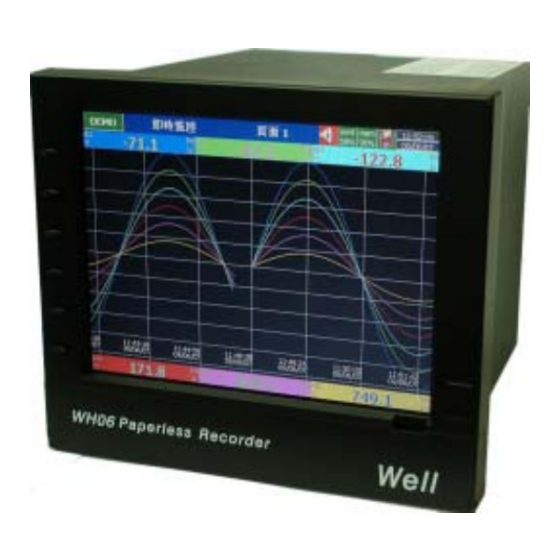
- Page 1 User Manual Paperless Recorder WH18/06 15th Edition, 03/2008...
-
Page 2: Table Of Contents
Contents Page Safety --------------------------------------------------------------------------------- Safety Symbols ------------------------------------------------------------------------ Safety Notes and Precautions ----------------------------------------------------- Static Electricity ----------------------------------------------------------------------- 1. General Description ------------------------------------------------------------------- 1.1 Unique Features of Recorder ------------------------------------------------------ 1.2 Expandable Input and Output cards --------------------------------------------- 1.3 Communication ----------------------------------------------------------------------- 1.4 Storage Media CF card -------------------------------------------------------------- 1.5 Data Security -------------------------------------------------------------------------- 1.6 Infrared Detector --------------------------------------------------------------------- 1.7 Ordering Codes and Accessories -------------------------------------------------... - Page 3 4. Configuration -------------------------------------------------------------------- 4.1 Channel ( Analog input, Digital input, Analog output, Math input ) -------- 4.2 Display ---------------------------------------------------------------------------- 4.3 Tools ( Timer, Counter & Totalizer ) ---------------------------------------------- 4.4 Instrument ------------------------------------------------------------------------- 4.5 Clock ------------------------------------------------------------------------------------- 4.6 Security & FDA 21 CFR part 11 compliance -------------------------------- 4.7 Demo -------------------------------------------------------------------------- 4.8 System Info ------------------------------------------------------------------------------ 4.9 A Configuration Example ------------------------------------------------------------...
-
Page 4: Safety
Safety This recorder is compliant with the requirements of EN61010-1, UL 61010C-1 & CSA C22.2 No. 24-93. The protection provided by the recorder may be impaired if it is used in a manner inconsistent with its intended purpose, or in an environment that exceeds the specifications of the recorder. -
Page 5: Static Electricity
6. When cleaning the recorder, handle carefully and use soft dry cloth. Avoid the use of abrasives or any sharp and hard objects, which would damage the display. 7. Do not operate the recorder if any part has been removed or disassembled. Consult your nearest dealer at once. -
Page 6: General Description
1. General Description 1.1 Unique features of recorder The WH18/06 is a well-designed paperless recorder with many outstanding features including: • 6.4〞TFT Color LCD with VGA Display in 640x480 pixels. • 18 isolated Analog Inputs • Plug & play I/O cards for easy expansion •... -
Page 7: Storage Media Cf Card
1.4 Storage Media CF Card The Solid Compact Flash Memory Card (CF card) 128 MB capacity is a free standard storage media used for this instrument. Its compact size, anti-dust and anti-vibration features increase its reliability. To read measured data on CF Card, add a CF reader on USB port of PC. Higher capacity 512 MB and 1GB CF Cards are upon request. -
Page 8: Ordering Codes And Accessories
1.7 Ordering codes and accessories Ordering codes WH18/06 – □□□□ – □□□ – □□□ 1 2 3 4 – 5 6 7 – 8 9 10 Power 4: 90-250 VAC, 47-63 Hz 5: 20-28 VAC, 47-63 Hz 6: 11-18 VDC 7: 18-36 VDC 8. - Page 9 with Mathematics, Counter & Totalizer & FDA 21 CFR part 11 compliance Storage Media 256MB Compact Flash card 512 MB CF card 刪除: 4: 256 MB CF card 1 GB CF card X: other options Case/Mounting standard panel mounting, grey case Bench top / portable style with handle, USA power cable, grey case Bench top with handle, European power cable, grey case standard panel mounting, black case...
- Page 10 The basic PC software Observer I is supplied free together with recorder. There is an additional charge for the extensive PC software Observer II supplied with communication of RS-232/422/485 or Ethernet. The Ordering Code of standard model without any option is WH18/06-4X00-010-110 ◆...
-
Page 11: Specifications
刪除: 1.8 Specifications Power 90-250VAC, 47-63Hz, 60VA, 30W maximum 11-18VDC or 18-36 VDC, 60VA, 30W maximum Display 6.4〞TFT LCD, 640X480 pixel resolution, 256 colors Memory 16MB storage memory on board Storage media: 256, 512 MB, 1 GB CF (Compact Flash) cards Analog Input Cards (AI181, AI182, AI183) Channels: AI181 ~ 1 channel, AI182 ~ 2 channels, AI183 ~ 3 channels Resolution: 18 bits... - Page 12 -250 ~ 1300 ˚C ±1 ˚C 2.2MΩ (-418 ~ 2372 ˚F) -200 ~ 900 ˚C ±1 ˚C 2.2MΩ (-328 ~ 1652 ˚F) PT100 -210 ~ 700 ˚C ±0.4 ˚C 1.3KΩ (DIN) (-346 ~ 1292 ˚F) PT100 -200 ~ 600 ˚C ±0.4 ˚C 1.3KΩ...
- Page 13 Output Rating: 24 ± 1 VDC, 180mA in maximum, 30mA / each channel COMM Module (CM181) Interface: RS-232 (1 unit), RS-485 or RS-422 (up to 247 units) Protocol: Modbus Protocol RTU mode Address: 1-247 Baud Rate: 0.3~38.4 Kbits/sec. Measured data Bits: 7 or 8 bits Parity Bit: None, Even or Odd Stop Bit: 1 or 2 bits Standard Ethernet Communication...
-
Page 14: Installation And Wiring
Immunity: EN61326 (EN61000-4-2, EN61000-4-3, EN61000-4-4, EN61000-4-5, EN61000-4-6, EN61000-4-8, EN61000-4-11) 2. Installation and wiring 2.1 Unpacking If any damage is found while unpacking, the user should contact the local representative at once. It is suggested that the special packaging is retained for possible future requirement. 2.2 Installation Remove stains from this equipment using a soft, dry cloth. - Page 15 The right side Figure 2 - 2 Panel Cutout ( standard DIN size 138 mm x 138 mm ) Figure 2 - 3 Note: Do not over tighten mounting clamp screws that could result in distortion of the case. There is no mounting angle restriction.
- Page 16 Bench top / Portable style If the recorder is used for Bench Top or portable purpose, then the assembly Kit MK184 (two ears, one handle, two feet included) is required. Assemble as follows, Firstly, put the right ear FV-R on the right hand side of metal case, and slide it into the case by pushing in direction as shown in Figures 2-4 through Figure 2-8.
- Page 17 Figure 2 - 6 Figure 2 - 7 Figure 2 - 8...
- Page 18 Holding the handle so that the instruction side can be seen, pull the handle outward by both hands and put it in vertical position on the top of case. Then, slide the handle into both ears as Figure 2-9. Rotate the handle downward as Figure 2-10 & 2-11. Lastly, slide both feet beneath the case and straighten up the stoppers as Figure 2-12 ∼...
- Page 19 Figure 2 - 10 Figure 2 - 11...
- Page 20 Figure 2 – 12 Figure 2 – 13 Figure 2 – 14 Note: To change the bench top into panel mount. Disassemble kit MK184 (one handle, two feet, and two ears) in reverse of above, then fit the mounting clamps.
-
Page 21: Setup Input, Output & 24Vdc Power Supply Cards
2.3 Setup input, output & 24VDC power supply cards Analog input cards ( part numbers AI181, AI182, AI183 ) AI181, AI182, AI183 are analog input cards in 1, 2, 3 channels respectively. Each card includes universal input of TC ( J, K, T, E, B, R, S, N, L ), PT100, mV, mA, V. To select a specific input, first set jumpers and switches according to the sticker information on the card as Figure 2–15, and plug it into the rear slot then power on. - Page 22 Analog input card ( part number AI183V ) AI183V are analog input cards in 1, 2, 3 channels respectively. Each card includes linear input of ± 60mV, ± 20mA, ± 2V, and ± 20V only. To select a specific input, first set jumpers and switches according to the sticker information on the card as Figure 2–16, and plug it into the rear slot then power on.
-
Page 23: Wiring Of The Cards
2.4 Wiring of the cards Wiring Precautions 1. Care must be taken to ensure that maximum voltage rating specified on the label is not exceeded. 2. For the panel-mount version, it is recommended that near the equipment an external fuse and an external switch rated at 2A/250 VAC should be equipped. - Page 24 Analog input cards ( AI181, AI182, AI183 ) Figure 2 – 18 Analog input cards ( AI183V ) Figure 2 – 19 Digital output card ( DO181 ) Figure 2 – 20...
- Page 25 Digital input card ( DI181 ) Figure 2 – 21 Analog output card ( AO183I & AO183V ) Figure 2 – 22...
-
Page 26: Rs-232, Rs-422, Rs-485 Wiring
24 VDC auxiliary power supply card ( AP181 ) Figure 2 – 23 2.5 RS-232, RS-422, RS-485 wiring Figure 2 – 24... - Page 27 Figure 2 – 25 Figure 2 – 26...
-
Page 28: Installation Of Compact Flash Cf Card
2.6 Installation of Compact Flash CF card A 256MB Compact Flash Card is installed in each WH18/06. If a bigger capacity Compact Flash card is required, and the user decides to buy it locally, please check the brand name of CF card first. -
Page 29: Basic Operation
3. Basic Operation After installation and wiring, power on the recorder, six soft keys Page, Mode, History, Event, Status and Exit will appear on the left hand side of LCD display. Opening the plastic cover at the front of the recorder, the user may find another five soft keys Dump, Clear, Operate, Config and Shutdown. -
Page 30: Mode
Keep pressing Page key, you will get Page All to display all enabled channels. Figure 3 – 2 3.2 Mode Press Mode key to select the different ways of displays, which include Mix, Trend, Bar or Digital mode. Mix: The display default is Mix mode. Several modes including horizontal/ vertical trend, bar and digital modes can be mixed together. -
Page 31: History
3.3 History Press History key, to display historical trend. Press directional keys ← → to backward or forward. Press Zoom key to zoom in the time scale. The Zoom can be done variously in 1 sec/dot, 1 hour/Page, 12 hours/Page, 1 day/Page or 1 week/Page. Press Back key going back to the original display. -
Page 32: Event
3.4 Event Press Event key, the Event /Alarm List displays general Events, Alarms and Reports. Press Mode key to choose Evnt/Alam ( Event/Alarm ) or Report. Event/Alarm It displays the Ack (acknowledgement), Type, Source, Active time, Clear time and Value of events or alarms. -
Page 33: Status
Active Time is the time that alarm status becomes active. Clear Time is the time when two conditions are met. Firstly alarm status is cleared and becomes normal, and secondly the user has acknowledged it. If any alarm occurs, the red buzzer icon on the top right starts to flash. After the cause of alarm is no longer met and the alarm is acknowledged, then the red buzzer icon disappears. -
Page 34: Exit
Totalizer. Display shows the status DI, DO, Counter or Totalizer at the present time. Counter and Totalizer are available if the option of Math, Counter & Totalizer was ordered before. 3.6 Exit Press Exit key to close existing operation, the soft keys on the left hand side disappear giving full display. -
Page 35: Small Icons
3.12 Small icons (on the top right side ): Figure 3 – 6 Buzzer: Appears by flashing in red whenever the alarm status occurs. The buzzer will disappear after the user acknowledges the alarm, and the process becomes normal. Evnt: The percentage of memory space left for events/alarms. For example, evnt 84% means 84% space left for events/alarms. -
Page 36: Configuration
4. Configuration Press the Config key to enter the Configuration mode. The following buttons appear: Channel, Display, Tools, Instrument, Clock, System Info and Demo. Meanwhile, the following soft keys appear at the bottom: Save, Load, Default and Back. Figure 4 – 1 Soft Keys Enter: First select the mode by pressing directional keys↑↓←... -
Page 37: Channel ( Analog Input, Digital Input, Analog Output, Math Input )
Back: Go back to the previous display. 4.1 Channel ( Analog input, Digital input, Analog output, Math input ) Analog input After entering the Configuration mode, select Channel and press the Enter key to get into Channel mode. It displays the Analog input AI first. Press directional keys〈 〉at the bottom to select the channel. - Page 38 Minimum: logging in minimum measured data at the sampling interval Maximum: logging in maximum measured data at the sampling interval Log Speed: It is the logging speed (recording speed) of measured data. Select Log Speed column, then choose 1, 2, 5, 10, 30, 60 or 120 seconds. Offset: It is offset value to correct the sensor error.
- Page 39 Job1, Job2: When an event occurs, the task to be performed is called the job. A typical example is to trigger an alarm buzzer in event of high temperature. Each pen can accept four events ( or alarms ) and each event can create two jobs. Please note that a job under Event is different from a job by pressing the Operate key.
- Page 40 ◆ Press Back key to return to real-time display, all configurations will be memorized ◆ The Digital output DO card with 6 relays can be set in Job1, Job2. It can be traced in System Info mode after installed into the Slot. Digital input Press DI key to select the Digital input.
- Page 41 Math input Press Math key to select the Mathematics input. Except for Expression, it is similar to do the setting up for Analog input above. Define the name, Description, and select Type, Log Method, Log Speed, Unit, Scale Low, Scale High, and Event. Enter Expression column, it appears Source, Operator and a keyboard.
- Page 42 Math Expressions and an example Expressions on recorder Mathematics Functions Addition Subtraction Multiplication Division SIN(x) sin(x) COS(x) cos(x) EXP(x) SQRT(x) Square root of x LN(x) TG(x) tan(x) CTG(x) 1/tan(x) ASIN(x) ACOS(x) ATG(x) LOG(x) ABS(x) Absolute of x SQ(x) ROUND(x) The closest integral number to x HI(x,y) The bigger value between x and y LO(x,y)
-
Page 43: Display
Define the Name, Description, enable Type, define Log Speed, Log Method, and do Math Expression / Equation. Then, select Display mode as 4.2 Display. Define mode, Trend Direction, Background color. If Pens 1, 2, 3 have been used for three analog inputs, then select Pen 4 to be used for Math. - Page 44 Color: Selects the color for each pen. Width: Selects the width of trend, 1-thin, 2-medium, 3-wide. Low: Defines the low scale for a pen on the display. High: Defines the high scale for a pen on the display. StatusBar: To make it convenient when viewing the status of Totalizer, Counter, DI or DO, the user may enable these items in the StatusBar.
-
Page 45: Tools ( Timer, Counter & Totalizer )
4.3 Tools ( Timer, Counter & Totalizer ) Press Back key, to return to the beginning of Configuration mode. Select Tools, then press Enter key to get into Tools mode. Timer, Counter and Totalizer are defined here. Counter and Totalizer are available only if the options of Math, Counter & Totalizer have been ordered before. Timer Figure 4 –... - Page 46 Daily, Weekly or Monthly: The timer works in selected interval of Real Time. Action: Disables or enables the timer. Job1, Job2: various jobs as described in 4.1 Channel, 2 jobs for each timer. An example of Timer & Report: A staff plans to get a daily report from the recorder about the minimum, maximum and average values of the process every day.
- Page 47 Figure 4 – 7 Counter Figure 4 – 8 Press directional keys〈 〉at the bottom to select one from 6 available counters. Name: Defines the name of counter. Desc: Defines the description for a specific counter on the display. Unit: Defines the unit of counter Preset: Defines the preset value for the counter.
- Page 48 Type: Select one of three options: None, Process Hi, Process Low Setpoint: Defines the set point of process value to trigger the counter. Job1, Job2: various jobs as described in 4.1 Channel, 2 jobs for each counter Totalizer Figure 4 – 9 Press directional keys〈...
- Page 49 Unit: Defines the unit of totalizing Preset: Defines the preset value for the totalizer. The totalizer starts from a preset value. Event: Defines the type, setpoint, Job1 or Job2. Type: Select one of three options: None, Process Hi, Process Low Setpoint: Defines the set point of process value to trigger the totalizer.
-
Page 50: Instrument
High xxxx Log Alarm Set DO Process xxxx Log Alarm Set DO Process The daily, weekly or monthly report indicates Totalizer data of each day, each week or each month respectively. 4.4 Instrument Press Back key, to return to the beginning of Configuration mode. Select Instrument then press Enter key to get into Instrument mode. - Page 51 10 minutes for Screensaver from the factory. The recorder continues to recode data while it is in the screen saving mode. The display turns on again by pressing any soft key or by Infrared sensor. When an alarm occurs, it turns on the display as well. Sensor: Off &...
- Page 52 or 115200. Data Format: Selects it from three different data formats. Ethernet: IP: Select Automation if the server on the network automatically allocates the IP address for the recorder. Select User Define to manually set a fixed address for the recorder. Two new columns will appear for keying in fixed addresses IP Address: Defines the correct address of the recorder on the network Subnet Mask: Defines the correct SubnetMask address on the network...
-
Page 53: Clock
4.5 Clock Press Back key, to return to the beginning of Configuration mode. Selects Clock then presses the Enter key to get into Clock ( Date/Time ) mode to set up the local time. Date Style: Selects either month/date/year or date/month/year Date/Time: Set up the local time. -
Page 54: Security & Fda 21 Cfr Part 11 Compliance
10 minutes, the user needs to key in password again. It also offers audit trail function to record the user, the timing and what type work he was doing on the recorder before. Incorrect password and unauthorized operation will be recorded into the event list as well. -
Page 55: Demo
Figure 4 – 12 Security level: Supervisor: The top Supervisor can define all the user names including other Supervisors and Operators total in 30 numbers including him. He can access all the keys too, and his Time of validity for the password is unlimited. Operator: He can access vertical keys to view the historical data, events and status but no authority to access horizontal keys to do configuration, neither to dump, clear data. -
Page 56: A Configuration Example
Figure 4 – 13 System Ver: It is the firmware version of the recorder. V2.20 means the present firmware version of recorder. Plus means with the option of Math, Counter, Totalizer & CFR-21. Boot ROM ver: It is version of Boot ROM. Memory (Free / Total): Indicates the percentage of free memory to total memory reserved on the recorder. -
Page 57: Pc Software And Communication Configuration
Here is a process required for a paperless recorder with 3-channels of 4-20mA input, 6-relay outputs and Ethernet communication for real-time monitoring. With, Analog input card AI183, not yet fitted into rear slot, set up 4-20mA input according to 2.3 Setup input and output cards, and then plug it into rear SLOT 1. - Page 58 CONFIG_VIEWER is for configuration of the recorder from PC. HIST_VIEWER is for monitoring historical trends in PC. REAL TIME_VIEWER is for real time data logging in PC. Observer I is supplied along with the recorder at free of cost. Observer II is supplied on additional charge for real time data logging applications through PC. System requirements Hardware PC with Minimum 200 MHz processor, 64 MB RAM...
- Page 59 CONFIG_VIEWER This is used for configuration of the recorder from PC. Start-Programs-Observer I / Observer II-Configuration Tool bar To open new project To open existing project file To save the project file settings in PC To delete the project file from PC To select bank (CF card/ Ethernet / RS 232) To select the channel (AI/AO/DI/DO/MATH) To select display...
- Page 60 For the first time configuration you can cancel the above window and select new project Enter the name of the project. Bank This is used to select physical connection between the recorder and PC. Three options are available 1. CF card 2.
-
Page 61: Ethernet Configuration
256 MB CF card shall be supplied along with the recorder. Standard Ethernet port (RJ 45 female) shall be available at the recorder. RS 232/ RS485 shall be supplied as additional options. 5.2 Ethernet Configuration It is possible to use PC software Observer II for data logging from multiple units of recorders connected on standard Ethernet. - Page 62 1. Make sure that network adapter in PC is properly configured. IP address, Subnet mask and Gateway should be configured at the PC for using Observer II program. Please contact System administrator to set Unique IP address for the PC. 2.
- Page 63 3 Rc+ 3 Tx+ 3 Tx+ 1 Rc+ 6 Rc- 6 Tx- 6 Tx- 2 Rc- 6. Connect proper UTP Ethernet cable as per the requirements and observe the communication status between the Recorder and PC/LAN HUB at the LED’s dedicated for the purpose near female RJ 45 connectors.
- Page 64 Open for Ethernet connection Enter the IP address of the Recorder System will ask “Do you want to receive configuration data now? (Y/N)” Click on “Yes” to upload the recorder configurations to PC. If Upload is successful, it shows message as “Configuration successful” and all the configuration settings of the recorder now available at PC.
-
Page 65: Rs 232, Rs485, Rs422 Configuration
If Upload is unsuccessful, it shown message as “No response from Recorder, connection fails”. If this is the case, please check the Ethernet cable connections at both the recorder and PC/LAN HUB side. Also make sure that green communication LED available for proper firm connection at RJ 45 connector. - Page 66 2. Also make sure that RS 232 port available at PC where observer software is installed. 3. Please refer to 2.5 RS 232/RS 485/ RS 422 wiring in details. 4. Set RS 232 communication settings at the recorder manually. Please refer to 4.4 Instrument and select RS 232 at PC transfer.
- Page 67 9. Click on OK after setting all above details. By default Node address is 1. If any change is there for the node address, then it should be set at recorder manually then enter the same node address in the above configuration. 10.
- Page 68 If this is the case, please check the RS 232 cable connections at both the recorder and PC. Also make sure that green communication LED available for proper firm connection at back RS 232 port available at recorder back side. If still communication is not established between the recorder &...
- Page 69 It is important to check COM port of PC to see whether it been properly set. My computer-Properties-Hardware-Device Manager – Ports – COM 1 – Properties Devise usage: It should be enabled Device status: The device is working properly. If above conditions are not met, then RS 232 port is having problem at PC. Contact system administrator for replacing the port or updating driver properly.
- Page 70 Make sure that RS 232 communication setting at the recorder and PC are equal.
-
Page 71: Cf Card Configuration
5.4 CF card Configuration 1. If no other higher capacity CF card been ordered, the standard 256 MB CF card shall be supplied along with the recorder. 2. Save configurations from recorder to CF card at Recorder. Configuration – Save. This step will make sure that all IO cards information as per jumper and Dip-switch selection will be saved in to the CF card. - Page 72 6. Select CF card using radial button 7. Click on to set CF path to receive the configuration data available in CF card. 8. Click on Yes to receive the configuration data from CF card to PC.
- Page 73 9. If Upload is successful, it shows message as “Configuration successful” and all the configuration settings of the recorder now available at PC. The information includes all channel details of Input/Output cards as per Jumper/switch settings. 10. If Upload is unsuccessful, it shown error message as “Configuration file does not exist”. This message indicates that configuration information is not available in the CF card.
-
Page 74: Configuration In Real-Time Viewer
5.5 Configuration in Real-Time Viewer Configuration data It is used to define the configuration of the recorder for Real-Time Viewer. Please note that the configuration of Real-Time Viewer can be redefined and independent to the configuration of recorder itself. Double click on channel in the above spreadsheet to show the following Modify tag data with email configuration. - Page 75 Select Send email option for the job as shown above. The Email on event will be received like this, Type:HiAlarm Source:AI1 ActiveTime:12/12/20059:49:59AM Value:23.8 Option Three options of Share, Email and Communication are to be defined. It is mainly to set email configuration and real time log speed.
- Page 76 Share: Share/do not share options are available for user selection. If share option is selected, then Observer data available in the computer can be shared from other computers. On selection of this share data, shared folder will be created in C:\Observer. For example, you have one recorder and wish to analyze historical data at different computer.
-
Page 77: Dde Dynamic Data Exchange
Bank: It is to modify the channel for communication between Recorder and Observer from Real-Time Viewer. Four banks are available. In each bank protocol options Disable, Modbus_RS232 and Modbus_TCP are available for user selection. This Bank is used for Real- Time Viewer only, which is different from the Bank used for recorder itself on Page 60. - Page 78 5.6 DDE dynamic data exchange DDE link Dynamic Data Exchange (DDE) is a standard inter-application communication protocol built into Microsoft Windows operating systems and supported by many applications that run under Windows. DDE takes data from one application and gives it to another application. It allows Windows programs that support DDE to exchange data between themselves.
- Page 79 proceed further. For example, if desktop is selected in the path, then the file should be available in the desktop. Please check up the desk top for the excel file. If the MS Office is not installed in the PC, then you cannot open the excel file created as above procedure.
- Page 80 If any “Error” test appears in any cell of Excel, possible reasons is no data available at selected tag. Check the data availability at the recorder and Observer software for a particular tag. If any “NAME” text appears in the Excel file, it indicates that particular tag is not configured properly.
- Page 81 DDE with third party applications Once the data is available at Excel at particular cell, then data can be exchanged with the third party applications like PLC, SCADA, and Visual Basic etc. If data is to be exchanged with PLC, then PLC programmer can write Visual basic macro in Excel from the following link Excel –...
- Page 82 Example 3 DDE between Observer software and SCADA (Allen-Bradley RSVIEW32) When the Real time viewer in Observer II is working well in PC, then the tag data from Observer software will be available in the expression format as follows =RealTime_Viewer|TagService!_AI1...
- Page 83 1) Open SCADA project 2) System – Node – Select DDE server as data source 3) Name = VR18 (No gaps ) 4) Application = RealTime_Viewer 5) Topic = TagService 6) Check enable in the box. (This node should be selected) 7) Now open the data base 8) Create analog tag with all the details similar to the tag at the recorder.
-
Page 84: Application Examples
6. Application examples Example 1: Flow measurement A level has to be converted into a flow according to the following formula. Q ( calculated flow speed in liter per minute ) = 0.0072*h *60 h ( level range in mbar per second ) = 0 – 30 mbar In 4.1 Channel Mode of Configuration, set AI1 as follows, Name: Level 1 Desc: xxxxxx... - Page 85 Example 3: Communicate recorder with mobile phone through SMS Mobile receiving process value and alarm messages from recorder via GSM8000 By using analog output card AO 183I and GSM controller GSM8000, it is able to retrieve process values and get alarms from the recorder to your Mobile via SMS through GSM system. Hardware requirements 1.
- Page 86 GSM 8000 controller: 8 Analog inputs, 4-20 mA GSM 8000 controller set up Insert SIM card in GSM controller, set up the controller as per user manual Enter Supervisor and Operator mobile numbers in GSM controller. These are the mobile numbers to which SMS message to be sent from the GSM controller.
-
Page 87: Trouble Shooting
7. Trouble shooting... -
Page 91: Faqs Frequently Asked Questions
8. FAQs frequently asked questions Q1: What is the maximum scale low and scale high values we can set in the recorder for the analog inputs and outputs? A1: The minimum low scales of analog input are various -19999, - 1999.9, - 199.99, - 19.999, - 1.9999, -0.19999 depending on the position of the decimal point The maximum high scales of analog input are various 45536, 4553.6, 455.36, 45.536,... - Page 92 Q6: What kind of security is available in recorder? A6: There are two kinds of security. The normal security offers a common password. The high security with FDA 21 CFR part 11 compliance is available from version 2.2 on both recorder and PC software Observer.
- Page 93 A12: If the user prefers using larger capacities CF card we usually recommend 256MB or 1GB. To be fully compatible, we only recommend one brand SanDisk CF card. Q13: What is the product warranty period of time? How does the user handle the defective recorder? A13: It is 18 months after shipping from Taiwan.
- Page 94 A19: For RS-232, RS-422, RS-485 communication, the protocol is Modbus RTU. For Ethernet communication, the protocol is TCP/IP. Q20: How many recorders can be connected in a network? A20: It depends on hardware interface selected. If it is Ethernet communication, maximum, 255 devices can be connected in the network, each device in unique IP address.
- Page 95 10 seconds 1200 days 4800 days 9600 days 120 seconds 14400 days 57600 days 115200 days Q26: Is it possible to display all the selected channels in one page on recorder? A26: Yes, press Page key to get to Page all mode. Then, all selected channels in digits can be displayed in one page.
- Page 96 solution is to uninstall the old Observer software as per procedure given in section 1.4 of this software guide. Then, install the new Observer software from CD supplied. If the problem still can’t be solved, then uninstall the old Observer software and create a back up for the historical and real-time folders under C:/Observer and remove Observer folder from C: Then install the new Observer software again.
- Page 97 Q37: I am getting the following message in Real time viewer. What to do next? A37: The firmware V2.21 or earlier version does not allow the user to key in special characters like “.” “,” “*” “+” “-” etc. in Tag name. The user may change the tag name, or update the recorder firmware and PC software to V2.31 to avoid error message above.
Need help?
Do you have a question about the WH18/06 and is the answer not in the manual?
Questions and answers