Table of Contents
Advertisement
Quick Links
Advertisement
Table of Contents

Subscribe to Our Youtube Channel
Related Manuals for Avtech AVX931

Summary of Contents for Avtech AVX931
- Page 1 314Z 1CH VIDEO SERVER INSTALLATION GUIDE Please read instructions thoroughly before operation and retain it for future reference. x931_931a_V1.1 314Z 1CH VIDEO SERVER INSTALLATION GUIDE Please read instructions thoroughly before operation and retain it for future reference. x931_931a_V1.1...
- Page 3 IMPORTANT SAFEGUARD All lead-free products offered by the company comply with the requirements of the European law on the Restriction of Hazardous Substances (RoHS) directive, which means our manufacture processes and products are strictly “lead-free” and without the hazardous substances cited in the directive. The crossed-out wheeled bin mark symbolizes that within the European Union the product must be collected separately at the product end-of-life.
- Page 4 MPEG4 Licensing THIS PRODUCT IS LICENSED UNDER THE MPEG4 VISUAL PATENT PORTFOLIO LICENSE FOR THE PERSONAL AND NON-COMMERCIAL USE OF A CONSUMER FOR (i) ENCODING VIDEO IN COMPLIANCE WITH THE MPEG4 VISUAL STANDARD (“MPEG-4 VIDEO”) AND/OR (ii) DECODING MPEG4 VIDEO THAT WAS ENCODED BY A CONSUMER ENGAGED IN A PERSONAL AND NON-COMMERCIAL ACTIVITY AND/OR WAS OBTAINED FROM A VIDEO PROVIDER LICENSED BY MPEG LA TO PROVIDE MPEG4 VIDEO.
-
Page 5: Table Of Contents
TABLE OF CONTENTS 1. PRODUCT OVERVIEW 1.1 Front Side ..........................1 1.2 Rear Side..........................2 2. CONNECTION 1.1 Front Side ..........................3 3. CAMERA ACCESS AND NETWORK CONFIGURATION 3.1 Network connection via LAN ....................4 3.2 Camera access via web browser ..................11 3.2.1 DDNS setting...................... -
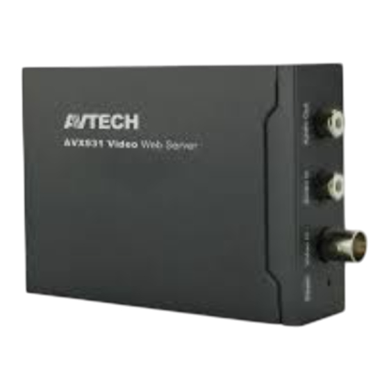
Page 7: Product Overview
1. PRODUCT OVERVIEW 1.1 Front Side CONNECTOR / DESCRIPTION BUTTON Reset This button is hidden in the pinhole. Press and hold the reset button until this device is rebooted. This will reset all parameters, including the IP address to factory default settings. Video In Connect to the video output connector of your camera with a video cable (i.e. -
Page 8: Rear Side
1.2 Rear Side CONNECTOR DESCRIPTION DC 12V Connect the DC 12V adapter for power supply. Alarm I/O Connect to an external device. There are five connectors, and they’re RS485-B, RS485-A, alarm-out, alarm-in, and GND respectively from left to right. Ethernet Connect the device to the network with the supplied RJ45 cable. -
Page 9: Connection
2. CONNECTION 1.1 Front Side Step1: Finish camera installation as described in its respective user manual. Step2: Connect the video ouput of the camera to the video input of this device with a video cable. Note: The video cable is not supplied within the sales package. Please purchase separately. -
Page 10: Camera Access And Network Configuration
3. CAMERA ACCESS AND NETWORK CONFIGURATION Before using this network camera, please follow the instructions below to finish the network connection settings based on your installation environment: To configure the network settings, you must connect the camera to your PC by LAN. For details, please refer to “3.1 Network connection via LAN”... - Page 11 For Windows XP users: a) Select “start” “Control Panel” “Network and Internet Connections” “Network Connections” (If you’re in “Category View”). For Windows XP users: b) Select “start” “Control Panel” “Network and Internet Connections” “Network Connections”...
- Page 12 c) In “LAN or High-Speed Internet”, right-click on “Local Area Connection”, and select “Properties”. Note: If your local area connection is not enabled, please also enable it. d) In the “General” tab, select “Internet Protocol (TCP/IP)”, and select “Properties”. e) In the “General” tab, select “Use the following IP address”, and set the IP address to “192.168.1.XXX”...
- Page 13 For Windows Vista users: a) Select “ ” (start) “Control Panel” “Network and Internet” to enter the “Network and Sharing Center”. Then, click “Manage network connections” (If you’re in “Category View”). b) Right-click on “Local Area Connection”, and select “Properties”. Note: If your local area connection is not enabled, please also enable it.
- Page 14 e) In the “Networking” tab, select “Internet Protocol Version 4 (TCP/IPv4)”, and select “Properties”. f) In the “General” tab, select “Use the following IP address”, and set the IP address as described below. Note: It’s recommended to note down the current settings first and then change as instructed.
- Page 15 For Windows 7 users: a) Select “ ” (start) “Control Panel” “Network and Internet” to enter the “Network and Sharing Center”. Then, click “Change adapter settings”. b) Right-click on “Local Area Connection”, and select “Properties”. Note: If your local area connection is not enabled, please also enable it. For Windows 7 users: c) Select “...
- Page 16 e) In the “Networking” tab, select “Internet Protocol Version 4 (TCP/IPv4)”, and select “Properties”. f) In the “General” tab, select “Use the following IP address”, and set the IP address as described below. Note: It’s recommended to note down the current settings first and then change as instructed.
-
Page 17: Camera Access Via Web Browser
3.2 Camera access via web browser Step1: Open your web browser, for example, Microsoft Internet Explorer, and enter “http://192.168.1.10” in the URL address box. Step2: In the login page, key in the default user name (admin) and password (admin), and enter the security code from the image below. - Page 18 For Static IP: Enter the information of “Server IP”, “Gateway” and “Net Mask” obtained from your ISP (Internet Service Provider). Enter the port number. The valid number ranges from 1 to 9999. The default value is 80. Typically, the TCP port used by HTTP is 80. However in some cases, it is better to change this port number for added flexibility or security.
-
Page 19: Ddns Setting
3.2.1 DDNS setting Step1: Click “Network” “DDNS”, and check “DDNS Enable”. Step2: Select “eagleeyes” in “System Name”. In “Hostname”, keep the default value, i.e. the MAC address of this camera, or change the name to a meaningful one. It’s easier to memorize. Then, note down the whole address of the camera, for example, MAC000e531d6ff1.ddns.dvrtw.com.tw. - Page 20 Step3: Click “Save” and log out. Then, disconnect your device and your PC, and connect them to Internet separately. Step4: Enter the host name you just note down in the URL address box of the web browser, and see if you can access the device successfully. Step3: Click “Save”...
-
Page 21: Appendix 1 Creating An Account For Ddns Service
APPENDIX 1 CREATING AN ACCOUNT FOR DDNS SERVICE For PPPOE or DHCP, you should enter the host name which points to the IP address of your network camera for login first. There are many websites for free DDNS service application, and below shows an example of DDNS account application from the website http://www.dyndns.com. - Page 22 Step2: Enter all the information necessary for signing up an account according to the website instructions. ‧Key in a user name for login, for example, headoffice523. ‧Set the password and input it again to confirm. ‧Key in your E-mail address and input it again to confirm. Then, click “Create Account”.
- Page 23 Step3: The system will automatically send a confirmation email to your email account. Please read this email within 48 hours and complete the procedure to activate your account according to the instructions in the email. When the account is confirmed, you will see “Account Confirmed”. Your account is created successfully now.
- Page 24 Step5: Click “Add Host Services”. ‧Input a meaningful host name. ‧Choose a host system name. ‧Enter the IP address you want to redirect. Step5: Click “Add Host Services”. ‧Input a meaningful host name. ‧Choose a host system name. ‧Enter the IP address you want to redirect.
- Page 25 Note down the whole host name, for example, headoffice523.dyndns.org. Then, click “Add To Cart” for billing. Note: This service is free. Just finish the billing process, and NO paying information is required. Step6: Click “Activate Services” after checkout, and you’re ready to use DDNS services now.
- Page 26 Step7: Return to your web browser, and go to “Network” “DDNS”. ‧ Select “Enable” for DDNS. ‧ Select the system name you set when subscribing the DDNS service from the drop-down list, for example, dyndns. ‧ Enter the user name & password you used to log into the DDNS service. ‧...
Need help?
Do you have a question about the AVX931 and is the answer not in the manual?
Questions and answers