
Related Manuals for Zell AC1000-3G


Summary of Contents for Zell AC1000-3G
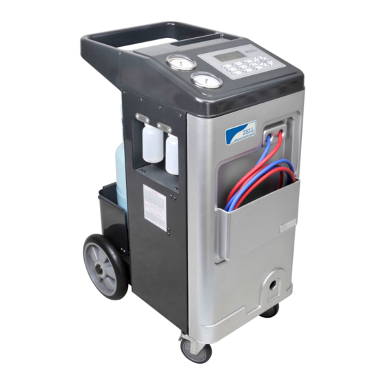
- Page 1 ® ZELL Mobile Air-Con Service Solution AC1000-3G Service Manual ZELL MOBILE AIR-CON SERVICE SOLUTION...
-
Page 2: Table Of Contents
..............2 1.1 ZELL hotline 2 Safety warnings . -
Page 3: Zell Hotline
1 About this service manual This service manual describes the service task of ZELL AC1000 Air-Con Service Station This manual is for those who perform repair and maintenance on AC1000 and have the expertise required to do so. This manual contains all the instructions necessary for safe and effective service operation of the AC1000 Station. -
Page 4: About This Service Manual
■If scale assembly and circuit are not calibrated, scale can overfill the tank, causing possible explosion and/or vehicle overcharge. ■Use only ZELL Designated Replacement Components when servicing your equipment. Refer to the operator’s manual or this service manual for correct replacement part number(s). -
Page 5: Electronic Diagrams
3 Electronic diagram 3.1 Main power diagram 3.2 Main control board diagram... -
Page 6: Flow Chart
4 Flow chart 4.1 Overall layout... - Page 7 AC1000-3G BLOCK AND SOLENOID LAYOUT...
-
Page 8: General Flow Chart
4.2 General flow chart 4.3 Recovery... -
Page 9: Purge And Drain Oil
4.4 Purge and drain oil 4.5 Vacuum... -
Page 10: Pag Oil Injection
4.6 PAG oil injection 4.7 Recharge... -
Page 11: Pressure Up
4.8 Pressure up 4.9 Pressure down... -
Page 12: Function Check
Function check 5.1 Recovery 5.1.1 The working tank must have at least 2.5Kg of refrigerant in it to perform this test. 5.1.2 Plug in the cord to 220V 50HZ power supply, Turn ON the main power switch. 220V 50Hz Power supply must be firmly grounded 5.1.3 Confirm that the HP, LP quick coupler and hoses are well fixed to the units. -
Page 13: Recharge
5.3 Recharge 5.3.1 Confirm that the HP, LP quick coupler and hoses are well fixed to the units. And all tank hoses are properly attached to the working tank. 5.3.2 Press Function button, and enter Other Service Item, use password 9227. Enter the M. -
Page 14: Load Cell Check
6 Load cell check 6.1.1 Press Function button, and enter Other Service Item, use password 7278. Enter the Data Info interface. There displays the raw data and the convert data, The Raw data is the original data from the load cell, the convert data is the manual handled data. To check if the scale is ok or not, remove the tank on the load cell plate. -
Page 15: Compressor Suction And Discharge Pressure Test
7 Compressor Suction and Discharge Pressure Test 7.1 General Spec. of compressor 7.1.1 Disconnect all fittings from the compressor. Cap the Suction port. Install a LP gauge on the process port. Install a HP gauge on the discharge port. Start the compressor and monitor the gauge readings the discharge pressure should build to 17 bar in HP gauge. -
Page 16: Trouble Shooting
8 Trouble shooting 8.1 No display Check for proper power source, check circuit breaker and electrical connectors for damage or corrosion.(Refer to compressor specifications on wiring diagram if needed. if not receiving power, check the continuity of the wring between solenoid and circuit board-repair as needed. -
Page 17: Disposal
9 Disposal 9.1 Disposing of used fluids Used oil is hazardous waste. Do not mix used oil with other fluids. Keep used oil in suitable containers prior to disposal. 9.2 Disposing of packaging material ■The cardboard packaging material should be disposed of with other waste paper. ■Plastic packaging material should be added to other recyclable waste. -
Page 18: List
10. Spare part list Parts Specification Hermetic R134a compressor COM013 Vacuum pump PUM101 Filter drier DRY080 Vacuum pump oil POL250 Solenoid valve (sv1.6) SOL002 Solenoid valve (sv3) SOL003 Low pressure gauge GAL080 High pressure gauge GAH080 Tank pressure gauge GAT040 Service hose for low pressure side(blue) HSB250 Service hose for high pressure side(red) - Page 19 pressure 8. High pressure 18.Low pressure 19.High pressure gauge gauge switch switch 10.Service hose for low pressure 6. Solenoid valve 24.Liquid hose (SV6) 23.Vapor hose 12.Service coupling for low pressure 20.Drain oil switch 17.Tank 13.Service coupling for high pressure 4.Fan 11.Service hose high pressure...
- Page 20 ZELL, Always Solution Add: No.2,XINGCANG MINLIAN INDUSTRY DEVELOPMENT ROAD HAINING DINGQIAO ZHEJIANG PROVINCE Tel: 0086 0573 8783 1215 Fax: 0086 0573 8786 6636 E-mail: zell.chief@gmail.com...