Table of Contents
Advertisement
Advertisement
Table of Contents

Related Manuals for Zell AC1800


Summary of Contents for Zell AC1800
- Page 1 ® Automobile Air-Con Service Station AC1800 Operation Manual...
-
Page 2: Table Of Contents
1 About this operation manual ...................... 2 1.1 Zell hot-line ..........................2 2 For illustrating the symbols in this operation manual ..............3 2.1 Scope of delivery ........................4 3 Safety ............................5 3.1 General safety instructions ..................... 5 3.2 Warnings on the Air-Con Service Station ................ -
Page 3: About This Operation Manual
1 About this operation manual This operation manual describes the Zell Air-Con Service Station This manual is for those who have the required professional ability of providing the maintenance service on vehicle air conditioning system. This manual contains all the instructions necessary for safe and effective operating of the air Conditioning service Station. -
Page 4: For Illustrating The Symbols In This Operation Manual
2 For illustrating the symbols in this Format Meaning Example Symbols used on the device Press „BOLD” „LANGUAGE” Display messages ■ ■ List in any order Text Pressure monitor ■ ■ Text Pressure relief valves 1. Text Actions to be carried out in the 1. -
Page 5: Scope Of Delivery
After delivery, please check all the parts listed below are present and undamaged. If any part is missing or damaged, notify the company responsible for transport immediately AC1800 Air-Con Service Station Blue hose with coupling for LP connection and red hose with HP connection 2 Containers for new oil... -
Page 6: Safety
→ Wear personal safety equipment (goggles and gloves) and avoid touching refrigerant, as this can cause chilblains to your body. → Use only Zell approved storage cylinder, part NO.5150998 with this refrigerant recovery unit. → Only use genuine R134a refrigerant .If other refrigerants are mixed in, it can damage the Air-Con Service Station and the vehicle air condition system. - Page 7 located at least 18(457 mm) in above the floor. Do not inhale refrigerant gas . Although the gas is non-toxic, it displaces the oxygen you needed. → This equipment should NOT be used in the vicinity of spilled or open containers of gasoline.
-
Page 8: Warnings On The Air-Con Service Station
3.2 Warnings on the Air-Con Service Station Be careful Observe the operation manual. Protect the device against rain Wear gloves when handling refrigerants. Wear goggles when handling refrigerants. Horizontal holding the station Caution for fire 3.3 Safety devices Pressure monitor: switch the compressor off if the normal ■... -
Page 9: Proper Use
Zell assumes no liability for damage resulting from the following: Use for purposes more than those described in this operation manual. ■ Modification to the Air-Con Service Station without the permission of Zell ■ Damage to the device resulting from external influences. -
Page 10: Overview Of The Air-Con Service Station
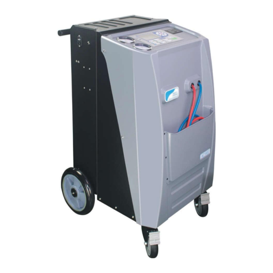
5 Overview of the Air-Con Service Station (1) (2) (12) (7) (3) (10) (back) (5) (6) (8) (4) (9) (13) (inside) (11) (1)used oil bottle (2)new oil bottle (3)uv oil bottle (4)pressure gauge for HIGH and LOW (5)LCD (6)HP and LP hoses (7)pressure gauge for working tank (8)working tank (30Lbs) (9)heating belt (optional item) -
Page 11: User Communication Interface
5.1 USER COMMUNICATION INTERFACE: Auto key: one press operation for all steps automatically Recovery : to recover the A/C refrigerant into the working tank Vacuum : to extract Non-condensable gases from A/C system New oil : to inject new oil into vehicle A/C system. UV : to inject UV into vehicle A/C system. - Page 12 print : Record the operations and to print receipt. OK : it allows to start the operation step. cancel the operation step. Stop : it allows to Home: come to the main interface. Back: back to the previous interface. next step: go to the next interface. Menu: Access to functional interface.
-
Page 13: First Start-Up
6 First start-up 6.1 Setting up and switching on 110-120V 60Hz or 220-240V 50Hz Power supply must be firmly grounded. If not, it will cause the weight scale a incorrect operation; it also may cause an injury to operators from an electric shock. -
Page 14: Installing In The Bottle For New Oil
6.2 Installing in the bottle for new oil Unscrew the refrigerant oil bottle, put about 150 ml new oil in and screw it back to the device. 6.3 Filling up the working tank When the Air-Con Service Station is started for the first time, the internal refrigerant container is suggested be filled gas with at least 6 kg from an external refrigerant cylinder. - Page 15 ONE IS THE VAPOR PORT OF THE SOURCE TANK Only LIQUID refrigerant is recommended. ■ For other type of source tank, be sure that Only Liquid port should be connected to the refill adapter. BLUE ONE IS THE LIQUID PORT OF THE SOURCE TANK 1.On standby mode, put the refill connector to the refrigerant bottle and fix it, then join the LP adapter with the Low pressure hose(blue) to the connector, open the adapter, open the bottle valve and up side down it.
- Page 16 Tip: The filling will stop automatically when the quantity of refrigerant is desired, the LCD will show 3. Close the refrigerant bottle valve and disconnect the LP adapter, 4. press to confirm. And start hose cleaning operation to collect the gas reminded in hose !
- Page 17 you should recover the refrigerant. If you do not recover the Note1: refrigerant inside the hose, it will cause refrigerant leakage when you release connections, as this can cause frosty. you can not select the recovery operation to instead of this one, Note2: or it will speed up the usage of filter driers.
- Page 18 6. Press to confirm, disconnect the LP adapter from the external refrigerant bottle. And the program will come back to the standby mode.
-
Page 19: Operation
7 Operation When the automobile air-conditioning is serviced, the engine and the air-conditioning must be switched off. 1.When you power on the machine, the LCD will stay at the standby mode. 2.press the , it will lets you input the license plate... - Page 20 3.touch the plate, it will show you a keyboard to input 4.when you finished your input, touch the to the option menu.
-
Page 21: Recovery
7.1 Recovery Recovery operation is the process that the Air-Con Service Station sucks the refrigerant from the vehicle A/C system, purity it and storage the gas into the working tank. The equipment could automatically detect the gas in the serviced vehicle is enough or not for the operation. - Page 22 1. Unscrew the caps of the service port on vehicle and put on the LP/HP adapters of the Air-Con Service Station and open them. 2. Check the HP and LP gauges. If the showed pressure is zero or about, it means that no refrigerant is in the air-conditioning system, you can select other functions directly.
- Page 23 process.it will show the below information fter first phase of recovery, you need to spend some minutes, just waiting for more refrigerant evaporating into vapor, if the pressure inside the A/C raised , the equipment will repeat the recovery process until the pressure will not raise any more.
- Page 24 6. For about 30-50 seconds, The oil draining process would be finished. 7.Touch key to stop the alarm buzzer, or touch key to print, then the recovery process finished!
-
Page 25: Vacuum And Vacuum Test
7.2 Vacuum and Vacuum Test Vacuum operation is the process that the Air-Con Service Station evacuate the vehicle A/C system into a vacuum state. The small quantity gases are exhausted outside. In the process, the pressure inside the A/C changes from the relative zero to absolute zero. - Page 26 2. Touch the number to set the vacuum time and test time, Finished the input, touch to confirm, It comes from the vacuum and to the test automatically. The device will show the blow information after expiry of the test time.
- Page 27 If testing passed, you will see If testing not passed, you will see Whatever the result, you can choose to touch the key to print or press to confirm and come back to the option menu. In fully auto mode, If the result is OK, the operation can go ahead, but if failed, the operation stop and will return to standby interface.
-
Page 28: Oil Injection
7.3 Oil injection This operation is to make up of new refrigerant oil into vehicle A/C system though the Air-Con Service Station. it must be a vacuum state that the new oil could be added into the A/C system. 1. Check the new oil bottle, make sure that the refrigerant oil is more than 50ml inside. - Page 29 2. Touch the number to adjust the oil quantity, 3. Confirmed the quantity, then touch bottom, the new refrigerant oil would be sucked into the A/C system. 4. Watch the scale of the PAG bottle, when the oil is added with the desired quantity, stopped the operation.
-
Page 30: Uv Injection
5. Touch the key to print or touch to confirm and come back to the standby mode. 7.4 UV injection This operation is to make up of UV oil into vehicle A/C system though the Air-Con Service Station. it must be a vacuum state that the UV could be added into the A/C system. - Page 31 more than 50ml 2. Touch the number to adjust the oil quantity, 3. Confirmed the quantity, then touch bottom, the new refrigerant oil...
- Page 32 would be sucked into the A/C system. 4. Watch the scale of the UV bottle, when the UV oil is added with the desired quantity, stopped the operation. it will finished automatically. 5. Press the key to print or press to confirm and come back to the standby mode.
-
Page 33: Recharge
7.5 Recharge This operation is to fill with the refrigerant into the vehicle A/C system though the Air-Con Service Station. the quantity is measured by load cell and it must be a vacuum state that the gas could be added into the A/C system. Usually, if the tank pressure is over than 6 bar, the recharge will be done quickly, or it need some special solution to resolve it. - Page 34 2. When all are ready, press to confirm. it will recharge the air-conditioning with the refrigerant. The process will be stopped automatically when the set quantity of refrigerant is completely filled into the A/C system .
- Page 35 Touch key to print or touch to confirm, and you will see This tip is to tell you take off the quick couples from the A/C system and screw back the valve caps to the service port. And empty the service hoses by recovery operation.
- Page 36 3.When all are ready, press to continue. the hose-cleaning operation will finished automatically and come back to the operation menu. Note1: some time the recharge maybe not finished in time, and the bellow information displayed: This is because tank pressure is not enough for the operation. Please go on the process by starting the automobile engine and A/C, CLOSE AND TAKE OFF THE HP ADAPTER FROM THE AC , only let the Low side to suck the gas into A/C system, it...
-
Page 37: Fully Auto
will automatically stop if the set gas quantity is finished 7.6 FULLY AUTO The automatic operation is including recovery, oil drain, vacuum and vacuum test, oil injection, and recharging, all steps are in one press. Before operation, you must confirm that the new refrigerant oil and the UV are enough, or it has risk that the air would be sucked into the vehicle A/C system. - Page 38 2. Touch the number to adjust all the parameters for the operation. 3. then touch the key to start, the device will automatically run the recovery, oil drain, vacuum and test, oil injection, recharging phases. This display indicates that the machine is diagnosing itself whether it is available for automatic.
- Page 39 After all the steps finished, it will give you all the data for confirming, you can take off the quick couples from the A/C system and screw back the valve caps to the service port. And empty the service hoses by hose-cleaning operation. The device is then ready for further use.
-
Page 40: Weigh Scale Verification
4.press to continue. the hose-cleaning operation will finished automatically and come back to the operation menu. 7.7 Weigh Scale verification This operation is for checking the output of the weigh sensor. If it does not work correctly, an additional calibration is needed. You need something with a known weight. - Page 41 1. Make sure the tank is fixed on the scale properly without any disturbance or leaning against. 2. In the standby mode , touch the machine 3 continuously , the LCD show: You can touch the sensor to choose which wight sensor for checking. for example, we choose the sensor of the tank, touch the W1 to enter.
- Page 42 It will show a 0 ± 5 as default, then put the sample weight on the tank. It shows 200 ± 5, it means the sensor is working well. If the total error is out of 5 gram, an additional calibration is needed. 3.
-
Page 43: Record Print
7.8 RECORD PRINT If there is a printer on the equipment, this data can be printed out as a receipt for customer. 1.in standby mode, touch the 2. it will lets you input the license plate 3.touch the plate, it will show you a keyboard to input At this time you can enter the user’s license plate and press to print. -
Page 44: Weight Scale And Pressure Sensor Zero
7.9 Weight Scale Zero and Pressure Sensor Zero Weight Scale Zero In order to make sure the refrigerant quantities correctly, the zero point of the scales must be checked regularly filter change and reset if necessary. Resetting is necessary: If the quantity deviates by more than 10g from the target value ■... - Page 45 The device prompts you to remove the fix screw and lift the tank off from the scale plate. 3. Make sure that there is NOTHING on the scale, press key . After finishing it, the LCD will warm you a flash to put back the screws and the tank, then the LCD will come to the sensor mode automatically.
- Page 46 Touch the come back to the standby mode. 4. place back the tank on the scale plate and fix the screw back. Please make sure that the tank is placed vertically without touching any wall.
- Page 47 Pressure Sensor Zero In order to make sure the pressure measure work correctly, the zero point of the pressure sensor must be checked regularly and reset if necessary. Resetting is necessary: If the quantity deviates by more than 20mBar from the target value ■...
- Page 48 4.The device prompts you to remove the low adapter and make sure that the hose is well connected to ATM, then press key . After finishing it, the LCD will come to the sensor mode automatically, put back the low adapter to the hose.
-
Page 49: Sd Card Data Editing
7.10 SD Card data editing The database provided by the factory is not necessarily comprehensive, ■ if you need to add model data, you can use the SD card for self-editing. 1.Remove SD card from motherboard. SD card 3. Use your computer for data editing. Open the data card and you will see a lot of car-branded notepads. -
Page 50: Service Tasks
8 Service tasks Other service are included this items as: 1.INNER TANK REFILL 1. LANGUAGE SELECT 2. WEIGHT UNIT 4.OTHER SERVICE If you want come to these items, please touch machine continuously and enter it. 8.1 Inner tank refill Refer to 8.2 Language select You can select English or other language. -
Page 51: Weight Unit
8.3 Weight Unit You can select grams or lbs. 8.4 Other service This operations are need the password, if you want to use this you can call the Zell hot line to ask for the password. -
Page 52: Disposal
9. Disposal 9.1 Disposing of used fluids 1.Used oil is hazardous waste. Do not mix used oil with other fluids. Keep used oil in suitable containers prior to disposal. 2.Disposing of used fluids should comply the local government laws. 3.Disposing of used filter should comply the local government laws. 9.2 Disposing of packaging material ■... -
Page 53: Trouble Shooting
10 Trouble shooting Fault Cause Remedy The display shows This message is „WARNING! normal, during the Press continue CODE: W16 recovery process. other operations. If you NOT ENOUGH PRESSURE make sure that there is no TO RECOVERY!” refrigerant in A/C system. The display shows The inner tank is full of Drain the internal... -
Page 54: Technical Data
11 Technical data Dimensions (width x height x depth) 550 mm x 1100 mm x 750 mm Weight 120 kg Power supply 220 V- 50 Hz Refrigerant R134a Vacuum pump 120L / min 2Stage Compressor 1/3 P tank capacity 14.6 kg (30 lbs) Filter driers ability 80kg HP/LP gauges size...