Advertisement
Quick Links
Advertisement

Related Manuals for CUSHCRAFT LFA-2M14EL


Summary of Contents for CUSHCRAFT LFA-2M14EL
- Page 1 Cushcraft Amateur Radio Antennas LFA-2M14EL 14 Element Loop Feed Beam For 2 Meters INSTRUCTION MANUAL CAUTION: Read All Instructions Before Operating Equipment Cushcraft Amateur Radio Antennas 308 Industrial Park Road Starkville, MS 39759 USA Tel: 662-323-9538 Fax: 662-323-6551 VERSION 1A...
-
Page 2: General Description
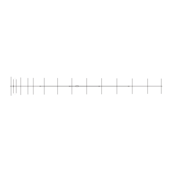
GENERAL DESCRIPTION The LFA (Loop Fed Array) Low-Noise Yagi is very different from the traditional dipole fed Yagi in many ways with its primary benefit being unwanted noise rejection. The LFA has a rectangular shaped, full wave loop driven element that is laid flat on the boom between and in-line with the parasitic elements . Then there is the way in which the loop functions. - Page 3 BOOM IDENTIFICATION Here are the 5 boom sections with measurements displayed for the pre-drilled holes. You won’t need these measurements, they are just there to identify the correct tube placement and orientation. Identify each tube by where the holes are. Once you have identified the tubes, determine which end of the tube will insert into the middle boom section.
-
Page 4: Boom Assembly
BOOM ASSEMBLY Place a #16 hose clamp over the tube before inserting next section Hose clamp Middle Boom Section 41.25 Note this hole toward rear of boom Rear Mid boom section SLOT Front Mid Boom Section SLOT 1-3/8 x .058 x 72 1-3/8 x .058 x 72 7.125 10.75... - Page 5 Long tube with saddle Rear of Antenna Element saddle and half washer. short tubes with insulator 8-32 x 2 8-32 nut #8 lock washer 7/16 X 14-1/2 7/16 X 14-1/2 Mount the insulator on the Boom at the second hole from the rear of the antenna using the 8-32 x 2 inch bolt.
- Page 6 Put one hose clamp over each end of each tube. Insert the loop ends into the 7/16 tubes. Don’t force them. Keep them straight as they go in. Leave them loose for tunning the SWR later. The tubes will have enough friction to stay without the hose clamps being tightened.
- Page 7 R1 41.5 INCH BROWN Color code chart R2 38.4 INCH RED R3 36 INCH ORANGE BLACK R4 36.5 INCH YELLOW BROWN R5 36.54 INCH GREEN R6 36.04 INCH BLUE ORANGE R7 35.83 INCH VIOLET YELLOW R8 35.58 INCH GREY GREEN R9 35.23 INCH WHITE BLUE...
- Page 8 Attach your coax to the feed loop using the remaining 8-32 nuts and lock washers. Make the distance of the exposed conductors as short as possible. Seal this connection using a appropriate sealant to prevent water from entering the coax. Wind a choke balun into the coax using a household cleaner or spray paint can.
-
Page 9: Boom Support
About 3 feet 12 element Antenna shown in vertical position for Illustration only. Boom support clamps are Tape coax to boom installed on the 1-1/4 inch end boom sections. and mast when mounted at its final loacation The antenna is now ready for mounting on your pole or tower. Route the coax along the boom and mast. -
Page 11: Parts List
PARTS LIST part # Description 190070 boom to mast 010401 u-bolt 564792 5/16 split washer 555747 5/16 hex nut 561177 1/4 lock washer 554099 1/4-20 hex nut 566344 FLAT WASHER 1/4 010404 UBOLT 745-3116S #16 hose clamp 745-3104S #4 hose clamp 455630 1-1/4 caplug 465420...
Need help?
Do you have a question about the LFA-2M14EL and is the answer not in the manual?
Questions and answers