Advertisement
Quick Links
Cushcraft
Amateur Radio Antennas
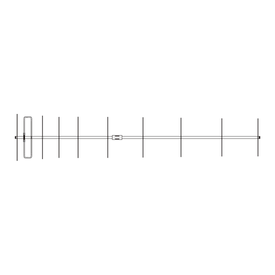
LFA-220M10EL
10 Element Loop Feed Beam
For 220 Mhz
INSTRUCTION MANUAL
CAUTION: Read All Instructions Before Operating Equipment
Cushcraft
Amateur Radio Antennas
308 Industrial Park Road
Starkville, MS 39759 USA
Tel: 662-323-9538 Fax: 662-323-6551
VERSION 1A
Advertisement

Related Manuals for CUSHCRAFT LFA-220M10EL


Summary of Contents for CUSHCRAFT LFA-220M10EL
- Page 1 Cushcraft Amateur Radio Antennas LFA-220M10EL 10 Element Loop Feed Beam For 220 Mhz INSTRUCTION MANUAL CAUTION: Read All Instructions Before Operating Equipment Cushcraft Amateur Radio Antennas 308 Industrial Park Road Starkville, MS 39759 USA Tel: 662-323-9538 Fax: 662-323-6551 VERSION 1A...
-
Page 2: General Description
GENERAL DESCRIPTION The LFA (Loop Fed Array) Low-Noise Yagi is very different from the traditional dipole fed Yagi in many ways with its primary benefit being unwanted noise rejection. The LFA has a rectangular shaped, full wave loop driven element that is laid flat on the boom between and in-line with the parasitic elements . Then there is the way in which the loop functions. - Page 3 5/16 nut Assembly of the Boom 5/16 washer 1/4-20 nut 1/4 washer Select the boom-to-mast clamp, (385142-1) the boom-to-mast bracket (385144-1) and four (4) 1/4" - 20 x 3/4" bolts (505266) BOOM four (4) internal lockwashers (562961) 1/4-20 x 3/4 and four (4) 1/4"...
- Page 4 Loop Assembly To assemble the feed loop onto the boom you will need the following parts. 2 feed loop ends 1 long 7/16 tube 1 insulator 2 short 7/16 tube 8-32 x 1 bolt 8-32 x 2 bolt 8-32 nuts and lock washers 8-32 x 2 8-32 Nut #8 split washer...
- Page 5 long tube with saddle Rear Boom Section short tubes with insulator Put one hose clamp over each end of each tube. Insert the loop ends into the 7/16 tubes. Don’t force them. Keep them straight as they go in. Leave them loose for tunning the SWR later.
- Page 6 INSTAL THE ELEMENTS 8-32 x 2 half washer R3 R4 R5 R6 R7 R8 element saddle The Rod elements are labeled with color bands using the standard resistor color codes. Starting from the rear of the antenna, the first rod is R1 and the last rod is R9. R1 is the reflector and R2 is the first director.
- Page 7 Once you have all the elements on in the correct location, check the alignment of the elements on the boom sections. Place the Boom caps on the ends of the antenna Attach your coax to the feed loop using the remaining 8-32 nuts and lock washers. Make the distance of the exposed conductors as short as possible.
- Page 8 Move out to shift frequency down Tuning Your antenna is now ready for tuning. Remove it from your assembly area and mount it on a temporary mast at least 8 feet off the ground. Using a SWR analyzer or radio and SWR meter, check for a dip in swr at or about 220.000 MHZ.
- Page 11 Notes...
Need help?
Do you have a question about the LFA-220M10EL and is the answer not in the manual?
Questions and answers