
Related Manuals for Digital Wireless Corporation WIT2410

Summary of Contents for Digital Wireless Corporation WIT2410
- Page 1 WIT2410 2.4GHz Spread Spectrum Wireless Industrial Transceiver Integration Guide June 15, 1999 One Meca Way Norcross, Georgia 30093 www.digital-wireless.com (770) 564-5540...
- Page 2 About This Manual This manual is designed to allow integration of the Digital Wireless Corporation WIT2410 OEM module into complete products. Care has been taken to try and make sure all of the information in this manual is accurate. However, specifications can change over time and Digital Wireless cannot guarantee the accuracy of this information.
-
Page 3: Table Of Contents
5.2. Network Commands........................17 5.3. Protocol Commands ........................19 5.4. Status Commands.......................... 21 5.5. Memory Commands........................22 5.6. Modem Command Summary ......................23 6. WIT2410 DEVELOPER’S KIT......................24 6.1. COM24............................24 6.2. Demonstration Procedure......................25 6.3. Troubleshooting ..........................26 7. APPENDICES............................28 7.1. -
Page 4: Introduction
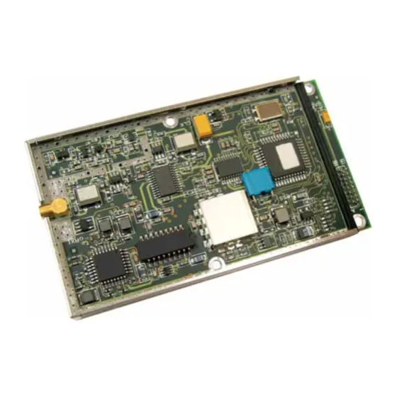
1. INTRODUCTION The WIT2410 radio transceiver provides reliable wireless connectivity for either point-to-point or multipoint applications. Frequency hopping spread spectrum technology ensures maximum resistance to noise and multipath fading and robustness in the presence of interfering signals, while operation in the 2.4 GHz ISM band allows license-free use and worldwide compliance. -
Page 5: Frequency Hopping Vs. Direct Sequence
Transmitting the data signal as usual, but varying the carrier frequency rapidly according to a pseudo-random pattern over a broad range of channels produces a frequency hopping spectrum system. © 1999 Digital Wireless Corporation 6/15/99... - Page 6 (including the U.S.) for the purpose of allowing compliant spread spectrum systems to operate freely without the requirement of a site license. This regulatory convenience alone has been a large motivation for the industry-wide move toward spread spectrum. © 1999 Digital Wireless Corporation 6/15/99...
-
Page 7: Radio Operation
The packet transmit delay parameter allows for the transmission of groups of continuous data in transparent mode (protocol mode 0). In TDMA mode the © 1999 Digital Wireless Corporation 6/15/99... -
Page 8: Data Transmission
Commands for complete details on parameters affecting the transmission of data. 2.2. Data Transmission The WIT2410 supports two network configurations: point-to-point and point-to-multipoint. In a point-to-point network, one radio is set up as the base station and the other radio is set up as a remote. -
Page 9: Point-To-Multipoint
For applications needing guaranteed bandwidth availability, the TDMA mode of the WIT2410 can meet this requirement. This is the default mode of the WIT2410. In TDMA mode, each remote has an assigned time slot during which it can transmit. The base station time slot is set independently of the remote time slots through the Set Base Slot Size command. - Page 10 = 47 bytes of data per hop. 17.36µs Note that the 47 bytes is the actual number of data bytes that can be sent. If the WIT2410 is using a protocol mode, the packet overhead does not need to be considered. So in this...
-
Page 11: Csma Mode
WIT2410 can still communicate reliably. Data input to the WIT2410 is broken up by the radio into packets. A 24-bit checksum is attached to each packet to verify that it was correctly received. If the packet is received... -
Page 12: Modes Of Operation
2.3. Modes of Operation 2.3.1. Control and Data Modes The WIT2410 has two modes of operation: Control mode and Data mode. When in Control Mode, the various radio and modem parameters can be modified. When in Data Mode, only data can be transmitted. The default mode is Data Mode. There are two ways to enter Control Mode. -
Page 13: Sleep Mode
2.3.2. Sleep Mode To save power consumption for intermittent transmit applications, the WIT2410 supports a Sleep Mode. Sleep Mode is entered by asserting the Sleep pin on the modem interface. While in Sleep Mode, the modem consumes less than 50µA. This mode allows the radio to be powered off while the terminal device remains powered. -
Page 14: Protocol Modes
The remotes may still use transparent mode without formatting to send data to the base, if desired. The WIT2410 supports 12 protocol formats which are described in detail below. The protocol format is selected through the Set Protocol Mode command. -
Page 15: Packet Formats
1110 1001 11HH HHHH 0111 1111 : handle number (0-63) : data length (0-127) : remote's previous network number (if roamed) : receive sequence number (from previous cell) : transmit sequence number (from previous cell) © 1999 Digital Wireless Corporation 6/15/99... -
Page 16: Data Packet
10HH HHHH 0111 1111 : handle number (1-62) When a remote goes out of range or roams to another cell, the base issues a disconnect packet to indicate that the remote is no longer available. © 1999 Digital Wireless Corporation 6/15/99... -
Page 17: Modem Interface
4. MODEM INTERFACE Electrical connection to the WIT2410 is made through a 16-pin male header on the modem module. The signals are 3.3 volt signals and form an RS-232 style asynchronous serial interface. The table below provides the connector pinout. -
Page 18: Interfacing To 5 Volt Systems
4.1. Interfacing to 5 Volt Systems The modem interface signals on the WIT2410 are 3.3 volt signals. To interface to 5 volt signals, the resistor divider network shown below must be placed between the 5 volt signal outputs and the WIT2410 signal inputs. The output voltage swing of the WIT2410 3.3 volt signals is sufficient to drive 5 volt logic inputs. -
Page 19: Modem Commands
5. MODEM COMMANDS The WIT2410 is configured and controlled through a series of commands. These commands are sent to the modem directly when the modem is in Control Mode or through Command Packets when the modem is in Data Mode. The command syntax is the same for either method, a one- or two-letter command followed by one or more parameters. -
Page 20: Network Commands
When using a protocol mode, make sure to count in packet overhead when calculating network performance. Refer to the section on Protocol Modes for details on each format. 5.2. Network Commands Network commands are used to set up a WIT2410 network and to set radio addressing and configuration. Command... - Page 21 Set Transmit Power The WIT2410 has two preset transmit power levels, 10mW (10dBm) and 100mW (20dBm). Control of the transmit power is provided through this command. Default is 100mW.
-
Page 22: Protocol Commands
However, link time can be reduced if this value is also programmed into the remotes, which use it as a starting value when scanning for the base. © 1999 Digital Wireless Corporation 6/15/99... - Page 23 When set to 1 selects redundant transmit mode that will send every packet packet attempt limit times regardless of success or failure of any given attempt. © 1999 Digital Wireless Corporation 6/15/99...
-
Page 24: Status Commands
5.4. Status Commands These commands deal with general interface aspects of the operation of the WIT2410. Command Description zb[?|0|1] Banner Display Disable 0 = disabled 1 = enabled (default) zc[?|0..2] Set Escape Sequence Mode 0 = disabled 1 = once after reset (default) 2 = unlimited times Read factory serial number high byte. -
Page 25: Memory Commands
5.5. Memory Commands The WIT2410 allows the user to store a configuration in nonvolatile memory, which is loaded during the initialization period every time the radio is powered up. Command Description Recall Factory Defaults m< Recall Memory m> Store Memory Recall Factory Defaults Resets the WIT2400 to its factory default state. -
Page 26: Modem Command Summary
Note: Brackets ([,]) as used here denote a set of optional arguments. Vertical slashes separate selections. For example, given the string wn[?|00..3f], legal commands would be wn?, wn0, wn3, and wn2a. Most commands which set a parameter also have a ? option which displays the current parameter setting; e.g., wn?. © 1999 Digital Wireless Corporation 6/15/99... -
Page 27: Wit2410 Developer's Kit
The pinout is provided in Section 7.3. The modems can be used with just a three wire connection. Transmit data, receive data and ground are the three required connections. Note that in this configuration, no flow control is available as the WIT2410 does not support software flow control. -
Page 28: Demonstration Procedure
Sets data rate of PC serial port to next higher value. Value is displayed in PgUp status line. Useful when COM24 is used to change the WIT2410 interface data rate. COM24 can communicate at new data rate without having to exit and re-enter COM24. -
Page 29: Troubleshooting
Can’t enter modem control mode. Make sure the host data rate is correct. The WIT2410 defaults to 9600 bps asynchronous. Evaluation units do not have external access to the CFG_SEL signal; you must use the :wit2410 power-on escape sequence to access modem control mode. - Page 30 Sometimes this symptom is caused by an application that is explicitly dependent on the timing of the received data stream. The nature of the packetized RF channel imposes a degree of unpredictability in the end-to-end transmission delay. © 1999 Digital Wireless Corporation 6/15/99...
-
Page 31: Appendices
(refer to section 7.6 for mechanical drawing) RF Connector: Huber/Suhner: 85 MMCX 50-0-1 Mating Huber/Suhner: 11 MMCX-50-2-3 (straight) Huber/Suhner: 16 MMCX-50-2-2 (rt. angle) Data/Power Connector: Samtec: DIS5-108-51-L-D Mating Samtec: FFSD-08 (IDC cable) Samtec: CLP-108-02-G-D (PCB mount) © 1999 Digital Wireless Corporation 6/15/99... -
Page 32: Serial Connector Pinouts
The WIT2410E can operate with just these three wires connected. However, as the WIT2410 does not support software flow control, there will be no flow control in this mode. If the DCE device fails to respond, connect DCD from the WIT2410E to the DTR and RTS inputs to activate the DCE device whenever the WIT2410 asserts carrier. -
Page 33: Mechanical Drawing
7.6. Mechanical Drawing © 1999 Digital Wireless Corporation 6/15/99... -
Page 34: Warranty
PROFITS, LOSS OF DATA OR LOSS OF USE DAMAGES ARISING OUT OF THE MANUFACTURE, SALE OR SUPPLYING OF THE GOODS. THE FOREGOING WARRANTY EXTENDS TO BUYER ONLY AND SHALL NOT BE APPLICABLE TO ANY OTHER PERSON OR ENTITY INCLUDING, WITHOUT LIMITATION, CUSTOMERS OF BUYERS. © 1999 Digital Wireless Corporation 6/15/99...
Need help?
Do you have a question about the WIT2410 and is the answer not in the manual?
Questions and answers