Table of Contents
Advertisement
Quick Links
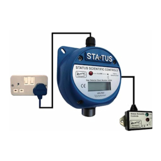
STATUS SCIENTIFIC CONTROLS
FGD14 Single Channel
Environmental Monitor,
Premier Infrared Sensor.
STATUS SCIENTIFIC CONTROLS LTD.
Hermitage Lane Industrial Estate,
Kings Mill Way,
Mansfield,
Nottinghamshire.
NG18 5ER
England
Tel
: 01623 651381
Fax
: 01623 421063
Internet
:
www.status-scientific.com
Issue:
3.0
Date:
16/5/19
Firmware:
V8.0.x
Advertisement
Table of Contents

Related Manuals for STATUS SCIENTIFIC CONTROLS FGD14

Summary of Contents for STATUS SCIENTIFIC CONTROLS FGD14
- Page 1 STATUS SCIENTIFIC CONTROLS Issue: Date: 16/5/19 Firmware: V8.0.x FGD14 Single Channel Environmental Monitor, Premier Infrared Sensor. STATUS SCIENTIFIC CONTROLS LTD. Hermitage Lane Industrial Estate, Kings Mill Way, Mansfield, Nottinghamshire. NG18 5ER England : 01623 651381 : 01623 421063 Internet www.status-scientific.com...
-
Page 2: Table Of Contents
STATUS SCIENTIFIC CONTROLS FGD14 Environmental Monitor Premier Infrared Sensor Introduction ....................3 ENSORS Installation ‘FGD14’ ..................4 ITING THE ................4 OWER UPPLY PTIONS 2.2.1 Mains Powered 2.2.2 DC Powered ..................5 ERMINATION 2.3.1 Remote Indicator Connection Menu System ....................7 ISPLAY ................ -
Page 3: Set Alarm Level
STATUS SCIENTIFIC CONTROLS FGD14 Environmental Monitor Premier Infrared Sensor TD06/026 Issue: Change note: 1882 Page 2... -
Page 4: Introduction
FGD14 Environmental Monitor Premier Infrared Sensor NTRODUCTION This variant of the manual is specifically for the FGD14 fitted with a Premier Infrared sensor. The FGD14 is a self-contained unit designed to detect environmental conditions by fitting suitable sensors. It also provides the user with local and remote indication of alarm / fault conditions. -
Page 5: Installation
Avoid mounting the instrument where it may be subjected to sudden transients in ambient temperature (e.g. above a heater/radiator). Power Supply Options The FGD14 is available with one of two power supply options. 2.2.1 Mains Powered A universal power supply is fitted that operates in the range of 85-265Vac, 47-400 Hz. -
Page 6: Wire Termination
Sensor module Remote keypad connector Note: When a DC Power Supply is fitted within the FGD14, the terminals marked L and N on the above diagram will be identified as +Ve and –Ve. TD06/026 Issue: Change note: 1882 Page 5... -
Page 7: Remote Indicator Connection
STATUS SCIENTIFIC CONTROLS FGD14 Environmental Monitor Premier Infrared Sensor 2.3.1 Remote Indicator Connection E N L Relay 2 Relay 1 To gain access to the terminals within the remote indicator assembly, remove the screw located at each corner of the assembly when viewed from below (4 in total). -
Page 8: Menu System
STATUS SCIENTIFIC CONTROLS FGD14 Environmental Monitor Premier Infrared Sensor YSTEM Important Whenever the menu system is entered the instrument will cease to measure current gas levels. However normal operation is always returned following a period of keypad inactivity (or when the menu system is exited). -
Page 9: Menu Mode Selection
To exit the calibration mode press MENU. While the instrument is in a calibration mode – any data displayed on the screen will alternate between the cal number and the reading. The following features are available via the ‘FGD14’ menu system: - Cal number Function... -
Page 10: Alarm Test
FGD14 Environmental Monitor Premier Infrared Sensor Alarm Test The FGD14 is equipped with an alarm test function. During alarm the relays, Leds and sounder will operate, see section 3.5 In order to gain access to the alarm test switch see section 3.1. -
Page 11: Zero
FGD14 Environmental Monitor Premier Infrared Sensor 3.4.2 Zero There are two zero functions within the FGD14, the instrument zero and the sensor zero. The sensor Zero can only be achieved internally. 3.4.2.1 Zero Instrument This is a calibration feature. It allows the instrument to determine the sensor output under zero gas conditions. - Page 12 STATUS SCIENTIFIC CONTROLS FGD14 Environmental Monitor Premier Infrared Sensor 3.4.2.2 Zero Sensor Remove the 4 screws located at each corner of the instrument to gain access to the sensor calibration buttons within the unit. Zero calibration of the sensor can be carried out by using the button on the circuit board as seen in Fig 1 below.
-
Page 13: Span
FGD14 Environmental Monitor Premier Infrared Sensor 3.4.3 Span There are two span functions within the FGD14, the instrument span and the sensor span. The sensor Span can only be achieved internally. 3.4.3.1 Span Instrument This is a calibration feature. It allows the instrument to determine the sensor output when it is exposed to a know concentration of gas. - Page 14 STATUS SCIENTIFIC CONTROLS FGD14 Environmental Monitor Premier Infrared Sensor 3.4.3.2 Span Sensor Always zero the sensor prior to performing a span operation. E N L Fig 2 Span Button Relay 1 Relay 2 Zero Span Apply a known concentration of gas (applicable to sensor type) at a flow rate of between 200 and 500cc/min.
-
Page 15: Set Instrument Fsd
STATUS SCIENTIFIC CONTROLS FGD14 Environmental Monitor Premier Infrared Sensor 3.4.4 Set Instrument FSD This option is used to match the sensor’s operating range with the electronics so that over-range conditions can be detected. • Select calibration mode C: 3 (refer to section 3.2) and press ENTER. -
Page 16: Display Firmware Version
STATUS SCIENTIFIC CONTROLS FGD14 Environmental Monitor Premier Infrared Sensor 3.4.6 Display Firmware Version Menu mode C: 7 This option is not available in this version – it is used for compatibility with other products. 3.4.7 Restore This feature is used to restore all the settings to the factory default settings. -
Page 17: View Engineer/Diagnostics Data
View Engineer/Diagnostics Data This feature is a view-only feature. No configuration changes are possible from within this menu. This information is for the use of Status Scientific Controls. • Select calibration mode C: 9 (refer to section 3.2) and press ENTER. -
Page 18: Set Relay 1 Mode
STATUS SCIENTIFIC CONTROLS FGD14 Environmental Monitor Premier Infrared Sensor 3.4.11 Set Relay 1 Mode The unit is fitted with a relay that is operated in conjunction with the alarm level. The user can select if the relay is normally energised, E’ or normally de-energised, ‘d’... -
Page 19: Sounder Enable
STATUS SCIENTIFIC CONTROLS FGD14 Environmental Monitor Premier Infrared Sensor 3.4.13 Set Alarm Level 1 • Select calibration mode C: 15 (refer to section 3.2) and press ENTER. • Using the UP and DOWN buttons, adjust the displayed reading so that it matches the desired alarm set point. -
Page 20: Set Alarm Hysteresis
STATUS SCIENTIFIC CONTROLS FGD14 Environmental Monitor Premier Infrared Sensor 3.4.16 Set Alarm Hysteresis Hysteresis is applied during alarm checking to stop the alarm relays chattering when the gas level is at the alarm set point. The hysteresis level is expressed as a percentage of the alarm setting. -
Page 21: Fgd14' Indications
The GREEN power led on the remote indicator is continuously lit. Alarm Condition If the FGD14 detects gas levels in excess of the preset alarm level, an alarm is raised. This is indicated by: The RED LED on the front panel of the FGD14 flashes and the sounder will be heard. - Page 22 If the instrument detects a fault with the sensor or the configuration data, a fault is raised. This is indicated by: The RED LED on the front panel of the FGD14 flashes and the display flashes F xxx, where xxx is a fault code as follows...
-
Page 23: Sensor Replacement
STATUS SCIENTIFIC CONTROLS FGD14 Environmental Monitor Premier Infrared Sensor Sensor Replacement Status Scientific Controls field service personnel, or a trained engineer should only perform sensor replacement. Consult Status Scientific Controls for further details. Following sensor replacement: - • A full calibration must be performed. -
Page 24: Trouble Shooting
FGD14 Environmental Monitor Premier Infrared Sensor ROUBLE HOOTING The ‘FGD14’ Infrared detectors have been extensively tested and have been found to provide reliable monitoring of Carbon dioxide gas levels. Any problems encountered by customers are usually the result of: •... -
Page 25: Specification
STATUS SCIENTIFIC CONTROLS FGD14 Environmental Monitor Premier Infrared Sensor PECIFICATION Size : 122 x 142 x 75mm nominal Weight : 0.9Kg Gas Types : Carbon Dioxide Operating Voltage : 85-265V, 47-400 Hz 2 user adjustable set points between 0.0%v/v Alarm set points and sensor FSD (5%v/v). - Page 26 STATUS SCIENTIFIC CONTROLS FGD14 Environmental Monitor Premier Infrared Sensor TD06/026 Issue: Change note: 1882 Page 25...
Need help?
Do you have a question about the FGD14 and is the answer not in the manual?
Questions and answers