Table of Contents
Advertisement
Quick Links
INSTALLATION / START-UP INSTRUCTIONS
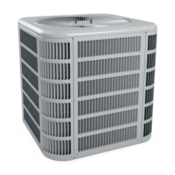
HRG14 SPLIT SYSTEM HEAT PUMP
HOMEOWNERS INFORMATION MANUAL
These instructions must be read and understood completely before attempting installation.
SAFETY PRECAUTIONS ......................................................................2
UNIT LOCATION & INSTALLATION ......................................................2
ROOFTOP INSTALLATION & RECOMMENDATIONS .........................3
CLEARANCE REQUIREMENTS ...........................................................3
REFRIGERATION LINE SETS ..............................................................3
INSTALLATION OF LINE SETS ............................................................4
LEAK CHECK ........................................................................................4
EVACUATING & CHARGING ................................................................4
OPENING SERVICE VALVE .................................................................4
These units are designed for use in residential and
light commercial type buildings. Heat Pumps may only
be installed with indoor combinations listed in the Air
Conditioning, Heating and Refrigeration Institute (AHRI)
Directory of Certified Products.
Inspect the unit for any damage before installation. If
damage is found, notify the transportation company
immediately and file a concealed damage claim.
Manufactured By
Comfort-Aire / Century
1900 Wellworth Ave.
Jackson, MI 49203
*P507710-01*
(P) 507710-01
507710-01
TABLE OF CONTENTS
These instructions must be left with the property owner.
ELECTRICAL CONNECTIONS ............................................................ 5
CONTROL WIRING .............................................................................. 5
START-UP PROCEDURE .................................................................... 6
ADJUSTING CHARGE ......................................................................... 6
SYSTEM OPERATIONS ...................................................................... 7
DEFROST SYSTEM (Time -Temp) ...................................................... 7
DEFROST SYSTEM (Demand Defrost) ............................................... 8
SINGLE PHASE WIRING DIAGRAM (14 SEER) ................................14
HOMEOWNER'S INFORMATION .......................................................15
Installation or repairs made by unqualified persons can
result in hazards to you and others. Installation MUST
conform with local building codes and with the National
Electrical Code NFPA 70/ANSI C1-1993 or current
edition and Canadian Electrical Code Part 1 CSA C22.1.
Improper installation, adjustment, alteration, service
or maintenance will void the warranty. The qualified
installer or agency must use factory-authorized kits
or accessories when added to this products. Refer
to the individual instructions included with the specific
accessory kit.
These instructions are intended as a general guide and do
not supersede national, state or local codes in any way.
Issue 1148
WARNING
CAUTION
NOTE:
Page 1 of 16
Advertisement
Table of Contents

Related Manuals for COMFORT-AIRE HRG14


Summary of Contents for COMFORT-AIRE HRG14
-
Page 1: Table Of Contents
INSTALLATION / START-UP INSTRUCTIONS HRG14 SPLIT SYSTEM HEAT PUMP HOMEOWNERS INFORMATION MANUAL These instructions must be read and understood completely before attempting installation. TABLE OF CONTENTS ELECTRICAL CONNECTIONS ............5 SAFETY PRECAUTIONS ..............2 CONTROL WIRING ................5 UNIT LOCATION & INSTALLATION ............2 START-UP PROCEDURE .............. -
Page 2: Safety Precautions
UNIT LOCATION & INSTALLATION NOTE TO INSTALLING DEALER These instructions and warranty are to be given to the owner NOTE: In some cases noise in the living area has been or displayed near the indoor air handler unit. traced to gas pulsations from improper installation of equipment. -
Page 3: Rooftop Installation & Recommendations
Elevate Unit DO LOCATE THE UNIT: • With proper clearances on sides and top of unit • On a solid, level foundation or pad CAUTION • To minimize refrigerant line lengths Accumulation of water and ice in base pan may cause DO NOT LOCATE THE UNIT: equipment damage. -
Page 4: Installation Of Line Sets
Installation of Line Sets Evacuating And Charging Instructions DO NOT fasten liquid or suction lines in direct contact with NOTE: Intentional release of CFC or HCFC refrigerant the floor or ceiling joist. Use an insulated or suspension type to the atmosphere violates Federal Law. It may also violate State and Local Codes. -
Page 5: Electrical Connections
Replace service valve cap and torque to 8-11 ft-lb on 3/8” valves; 12-15 ft-lb on 3/4” valves; 15-20 ft-lb on 7/8” valves. WARNING Use backup wrench on valve body when torqueing valve cap. The unit cabinet must have an uninterrupted or unbroken ground to minimize personal injury if an electrical fault Install Electrical Accessories should occur. -
Page 6: Start-Up Procedure
Heat Pump Application with Electric Heat Before final adjustment is made to the refrigerant charge, it is imperative that proper indoor airflow be established. Emergency Heat (heating heat pump) Airflow will be higher across a dry coil versus a wet coil. If selector switch on thermostat is set to the emergency heat Blower charts are calculated with a dry or wet coil basis. -
Page 7: System Operations
SYSTEM OPERATION The control provides automatic switching from normal heating operation to defrost mode and back. During compressor The outdoor unit and indoor blower cycle on demand from cycle, the control accumulates compressor run times at 30-, the room thermostat. When the thermostat blower switch is 60-, or 90-minute field-adjustable intervals. -
Page 8: Defrost System (Demand Defrost)
Compressor Delay DEMAND DEFROST SYSTEM DESCRIPTION The defrost board has a field-selectable function to reduce The demand defrost controller measures differential occasional sounds that may occur while the unit is cycling in temperatures to detect when the system is performing and out of the defrost mode. - Page 9 5-STRIKE LOCKOUT FEATURE Mode Green Led (DS2) Red Led (DS1) The internal control logic of the board counts the pressure switch trips only while the Y1 (Input) line is active. If a No power to control Normal operation/ pressure switch opens and closes four times during a Y1 Simultaneous Slow Flash power to control (Input), the control logic will reset the pressure switch trip...
- Page 10 Ambient Sensor—The ambient sensor considers outdoor Defrost Temperature Termination Shunt (Jumper) temperatures below -35°F (-37°C) or above 120°F (48°C) Pins—The defrost board selections are: 50, 70, 90, and as a fault. If the ambient sensor is detected as being open, 100°F (10, 21, 32 and 38°C).
- Page 11 OPERATIONAL DESCRIPTION Calibration success depends on stable system temperatures The defrost control board has three basic operational modes: during the 20-minute calibration period. If the board fails normal, calibration, and defrost. to calibrate, another defrost cycle will be initiated after 45 minutes of heating mode compressor run time.
- Page 12 Page 12 of 16 Issue 1148 507710-01...
- Page 13 Defrost Control Board Diagnostic LEDs 507710-01 Issue 1148 Page 13 of 16...
-
Page 14: Single Phase Wiring Diagram (14 Seer)
H/P 14 SEER WIRING DIAGRAM Page 14 of 16 Issue 1148 507710-01... -
Page 15: Homeowner's Information
Homeowner’s Information most thermostats. Ask your dealer for specific information regarding the model of thermostat installed. WARNING ELECTRICAL SHOCK HAZARD! Temperature Setting Levers Turn OFF electric power to unit before performing any Most heat pump thermostats have 2 temperature selector maintenance or removing panels or doors. - Page 16 On models without a fan Selection Switch, the fan will cycle Periodically, debris should be brushed from the condenser with the outdoor unit. coils. Important System Information WARNING • Your system should never be operated without a clean air filter properly installed. •...
Need help?
Do you have a question about the HRG14 and is the answer not in the manual?
Questions and answers