Table of Contents
Advertisement
Quick Links
Advertisement
Table of Contents

Related Manuals for IO Thrifty FMT-22


Summary of Contents for IO Thrifty FMT-22
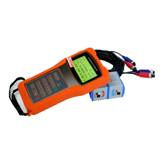
- Page 1 User’s Guide FMT-22 Ultrasonic Flow Meter...
-
Page 2: Table Of Contents
Website: www.IOThrifty.com | Email : service@IOThrifty.com | Phone: (860) 733-1117 Contents 1. Introduction ---------------------------------------------------------------------------------------1x 1.1 Preface -------------------------------------------------------------------------------------------1 1.2 Features ------------------------------------------------------------------------------------------2 1.3 Principle of Measurement -------------------------------------------------------------------2 1.4 Parts Identification ----------------------------------------------------------------------------3 1.5 Typical Applications ---------------------------------------------------------------------------6 1.6 Data Integrity and Built-in Time-Keeper --------------------------------------------------6 1.7 Product Identification -------------------------------------------------------------------------7 1.8 Specifications -----------------------------------------------------------------------------------7 2. - Page 3 2.8.3 Z-method Installation ----------------------------------------------------------------------16 2.8.4 W-method Installation ---------------------------------------------------------------------17 2.8.5 N-method Installation ----------------------------------------------------------------------17 2.9 Installation Checkup --------------------------------------------------------------------------17 2.9.1 Signal Strength -------------------------------------------------------------------------------17 2.9.2 Signal Quality ---------------------------------------------------------------------------------18 2.9.3 Total Transit Time and Delta Time -------------------------------------------------------18 2.9.4 Time Ratio between the Measured Total Transit Time and the Calculated Time ------------------------------------------------------------------------------------------------------------19 3.
- Page 4 3.19 How to use the OCT output ---------------------------------------------------------------24 3.20 How to modify the built-in calendar ----------------------------------------------------24 3.21 How to adjust the LCD contrast ----------------------------------------------------------24 3.22 How to use the RS232 serial interface --------------------------------------------------24 3.23 How to view the Date Totalizers ----------------------------------------------------------24 3.24 How to use the Working Timer -----------------------------------------------------------24 3.25 How to use the manual totalizer ---------------------------------------------------------25 3.26 How to check the ESN and other minor details --------------------------------------25...
-
Page 6: Introduction
The advanced circuit design, integration of the latest semiconductors, user-friendly software interface with both in English and Chinese languages and small-sized PCB board features combine to make the FMT-22 series ultrasonic flow meter one of the best on the market. -
Page 7: Principle Of Measurement
- 2 - built-in date totalizers built-in data-logger Work properly near transverters 0.5 second totalizing period 100 Pico-second resolution of time measurement 1.3 Principle of Measurement The ultrasonic flow meter is designed to measure the fluid velocity of liquid within a closed conduit. -
Page 8: Parts Identification
- 3 - Where θ is the include angle to the flow direction M is the travel times of the ultrasonic beam D is the pipe diameter Tup is the time for the beam from upstream transducer to the downstream one Tdown is the time for the beam from downstream transducer to the upstream one ΔT=Tup –Tdown 1.4 Parts Identification... - Page 9 - 4 -...
-
Page 10: Typical Applications
- 5 - 1.5 Typical Applications The flow meter can be applied to a wide range of measurements. The measured pipe ranges 20-6000 mm [0.5 - 200 inch] (optional transducers may be required). A variety of liquid applications can be accommodated: ultra-pure liquids, potable water, chemicals, grey water, reclaimed water, cooling water, river water, plant effluent, etc. -
Page 11: Product Identification
1.7 Product Identification Each set of the FMT-22 Series flow meter has a unique product identification or ESN written into the software that can only be modified with a special tool by the manufacturer. In case of any hardware failure, please provide this number which is located on menu window number M61 when contacting the manufacture. -
Page 12: Starting Measurement
- 7 - 2. Starting Measurement 2.1 Built-in Battery The instrument can operate either from the built-in Ni-H rechargeable battery, which will last over 10 hours of continuous operation when fully recharged, or from an external AC/power supply from the battery charger. The battery charging circuits employ a scheme of constant-current and constant- voltage. -
Page 13: Power
- 8 - the voltage is in the range of around 3.70 to -3.90 volt. 2.2 Power On Press the ON key to switch on the instrument and press the OFF to turn off the power. Once the flow meter is switched on, it will run a self diagnostic program, checking first the hardware and then the software integrity. -
Page 14: Menu Windows
- 9 - The keypad for the operation of the flow meter has 18 keys, as shown in below. Keys 0 ~ 9 and. are keys to enter numbers. Key ▲/+ is the going UP key, when the user wants to go to the upper menu window. - Page 15 - 10 - The OFF key is for the power off. 2.4 Menu Windows The user interface of this flow meter comprises about 100 different menu windows that are numbered by M00, M01, M02 … M99. There are 2 methods to enter certain menu window: ...
-
Page 16: Menu Windows Arrangement
- 11 - the option. In the end, the ENT key must be pressed to make the selection. For example, with menu window M14 for the selection of pipe material selection, (the MENU 1 4 should be pressed first to enter this menu window if the current menu window is on a different window. -
Page 17: Steps To Configure The Parameters
- 12 - M+0~M+8 are windows for some additional functions, including a scientific calculator, viewer on records such as total working hours, turn-on and turn-off times, dates and times when the flow meter has been turned on or turned off. Other menu windows such as M88 have no functions, or functions were cancelled because they are not applied to this version of the software. - Page 18 - 13 - diameter, and then press ENT key. (2) Press key ▼/- to enter M12 window to input the digits for the pipe outer diameter and then press ENT key. (3) Press key ▼/- to enter M14 window, and press ENT key to enter the option selection mode.
-
Page 19: Transducers Mounting Allocation
- 14 - (1) When the window display is between M00 to M09, press a number key x, the user will go directly to the M0x window. For example, if the current window displays M01, press 7 and the user will go to M07. (2) When the window display is under M00 to M09, press the ENT key and the user will go to M90;... - Page 20 - 15 - Principles to selection of an optimum location: (1) Install the transducers on a longer length of the straight pipe. The longer the better, and make sure that the pipe is completely full of liquid. (2) Make sure that the temperature on the location does not exceed the range for the transducers.
-
Page 21: Transducers Installation
- 16 - transducers that are installed permanently on the pipe by drilling holes on the pipe while liquid is running inside. 2.8 Transducers Installation The transducers used by the series ultrasonic flow meter are made of piezoelectric crystals both for transmitting and receiving ultrasonic signals through the wall of liquid piping system. -
Page 22: V-Method Installation
- 17 - 2.8.2 V-method Installation V-method installation is the most widely used mode for daily measurement with pipe inner diameters ranging from 20 millimeter to 300 millimeter. It is also called reflective mode or method. 2.8.3 Z-method Installation Z-method is commonly used when the pipe diameter is between 300 millimeters and 500 millimeters. -
Page 23: N-Method Installation
- 18 - 2.8.5 N-method Installation Rarely used method. 2.9 Installation Checkup Through the checkup of the installation, one can: check the receiving signal strength, the signal quality Q value, the traveling time difference of the signals, the estimated liquid speed, the measured traveling time of the signals and the calculated traveling time ratio. -
Page 24: Signal Quality
- 19 - to make sure the transducers spacing is the same as what the M25 shows. 2.9.2 Signal Quality Signal quality is indicated as the Q value in the instrument. A higher Q value would mean a higher Signal and Noise Ratio (short for SNR), and accordingly a higher degree of accuracy would be achieved. -
Page 25: How
- 20 - check: (1) If the pipe parameters are correctly entered. (2) If the actual spacing of the transducers is right and the same as what the window M25 shows. (3) If the transducers are installed properly in the right directions. (4) If the mounting location is good and if the pipe has changed shape or if there is too much fouling inside the pipes. -
Page 26: How To Select A Required Flow Rate Unit
- 21 - Use menu window M30 for the selection of unit system in English or Metric system. 3.4 How to select a required flow rate unit Use menu window M31 to select the flow unit first and then the timing unit. 3.5 How to use the totalizer multiplier Use window M33 to select a proper totalizer. -
Page 27: How To Use The Zero-Cutoff Function
- 22 - that means there is no damping. A bigger number brings a more stable effect. But bigger damper numbers will prevent the instrument from acting quickly. Numbers 0 to 10 are commonly used for the damper value. 3.10 How to use the zero-cutoff function The number displayed in window M41 is called the low-cutoff value. -
Page 28: How To Use The Built-In Data Logger
M52. 3.15 How to use the Frequency Output There is a Frequency Output in all FMT-22 series flow meters. This frequency output signal, which represents the flow rate, is intended to connect with other instruments. -
Page 29: How To Use The Totalizer Pulse Output
- 24 - window M69. Enter the frequency range in window M67. For example, assume that the flow rate varies in a range 0m3/h to 3000m3/h, and an output signal is at a maximum frequency of 1000Hz, the minimum of 200Hz is going to be required for other instrumentation. -
Page 30: How To Use The Built-In Buzzer
- 25 - Buzzer, and the other is the OCT output. Both for the Buzzer and OCT output the triggering sources of the event include the following: (1) Alarms on when there is no receiving signal (2) Alarms on when a poor signal is received. (3) Alarms on when the flow meter is not in normal measurement modes. -
Page 31: How To Modify The Built-In Calendar
- 26 - Please make sure that the Frequency Output shares the OCT. The OCT output shares pins with the RS-232C interface, and the terminal is at Pin 6 and the ground is at Pin 6. 3.20 How to modify the built-in calendar No modification on the built-in calendar will be needed in most cases. -
Page 32: How To Check The Esn And Other Minor Details
- 27 - Use M28 for the manual totalizer. Press ENT key to start and stop the totalizer. 3.26 How to check the ESN and other minor details Every set of the series flow meter utilizes a unique ESN to identify the meter. The ESN is an 8-digit number that provides the information of version and manufacturing date. -
Page 33: Menu Window Details
- 28 - 4. Menu Window Details... - Page 34 - 29 -...
- Page 35 - 30 -...
- Page 36 - 31 -...
- Page 37 - 32 -...
-
Page 38: Troubleshooting
- 33 - 5.Troubleshooting 5.1 Power-on Error Displays and Counter-Measures The FMT-22 series ultrasonic flow meter provides an automatic power-on diagnosis for the hardware problems. When any message (with the power on) in the following table displays, counter-measures should be taken. -
Page 39: Other Problems And Solutions
- 34 - 5.3 Other Problems and Solutions (1) When the actual flow inside the pipe is not standstill, but the instrument displays 0.0000 for the flow rate, and ‘R’ displaying signal strength and the signal quality Q (value) has a satisfactory value? The problems are likely caused by the user who has used the ‘Set Zero’... -
Page 40: Communication Protocol
- 35 - make sure that there is absolutely no flow in the pipe. (3) The battery does not work as long as the time period as indicated by M07 (a) Battery should be replaced due to the end of the service life. (b) Newly changed battery does not fit the battery estimating software. -
Page 41: The Protocol
- 36 - 6.2 the Protocol The protocol is comprised of a set of basic commands that is a string in ASCII format, ending with a carriage (CR) and line feed (LF). Commonly used commands are listed in the following table. -
Page 42: Protocol Prefix Usage
- 37 - Notes * CR stands for Carriage Return and LF for Line Feed. ** ‘d’ stands for the 0~9 digit numbers. *** @ stands for the key value, e.g., 30H for the ‘0’ key. 6.3 Protocol Prefix Usage (1) Prefix P The prefix P can be added before any command in the above table to have the returning data followed with two bytes of CRC check sum, which is the adding sum... -
Page 43: Codes For The Keypad
- 38 - The prefix N is a single byte IDN network prefix, not recommended in a new design. It is reserved only for the purpose of the compatibility with the former versions (4) Command Connector & The & command connector can connect up to 6 basic commands to form a longer command so that it will make the programming much easier. -
Page 44: Model Numbers
FMT-22-S Small pipe transducer set for pipes ½” to 4" FMT-22-M Medium pipe transducer set for pipes 2” to 28" (included with FMT-22) FMT-22-L Large pipe transducer set for pipes 12” to 240" FMT-22-AG... -
Page 45: Warranty Terms
- 40 - 8. Warranty Terms IOThrifty LLC ("IOThrifty") warrants that for a period of one year following delivery, the IOThrifty products you have purchased will (a) perform in accordance with published specifications, and (b) will be free from defects in materials or workmanship. In the event an IOThrifty Product does not meet this warranty, subject to the conditions set forth in these terms and conditions, IOThrifty’s sole obligation will be, at its election, to repair or replace the product in question or to refund the purchase price. - Page 46 - 41 -...
Need help?
Do you have a question about the FMT-22 and is the answer not in the manual?
Questions and answers