Table of Contents
Advertisement
Quick Links
Advertisement
Table of Contents

Related Manuals for IO Thrifty FMT-25W


Summary of Contents for IO Thrifty FMT-25W
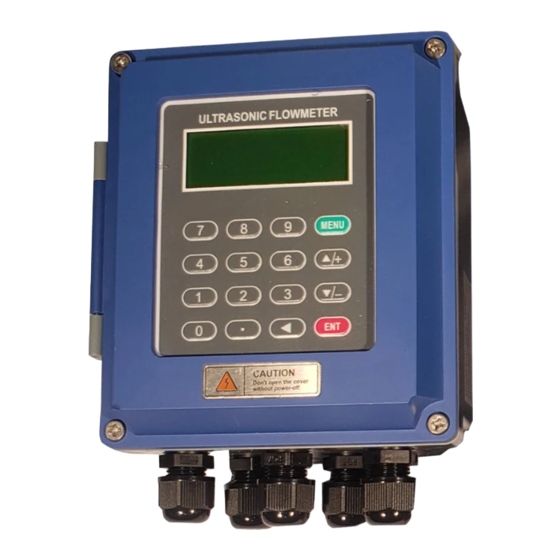
- Page 1 FMT-25W Ultrasonic Flow Meter User’s Guide V1.1...
-
Page 2: Table Of Contents
Check Components ....................2 Transducer Mounting Diagrams ................3 Mounting ....................... 3 Meter Installation and Wiring Diagram ..............3 FMT-25W-AB Installation Instruction ..............3 FMT-25W-AB Wiring Diagram ................5 FMT-25W-AE Mounting ..................6 FMT-25W-AE Wiring Diagram ................6 Transducer Introduction and Wiring Diagram ............8 Clamp Transducer .................... -
Page 3: Product Models
>>FMT-25W Ultrasonic Flow meter User Manual The FMT-25W is a new generation ultrasonic flow meter manufactured using patented technology which employs the transit-time principle to measure the velocity of relatively clean liquids in full pipes. The purpose of this guide is to provide installation procedures and basic operating instructions for the FMT-25W.General Installation Procedure... -
Page 4: Check Components
>>FMT-25W Ultrasonic Flow meter User Manual TC-1 (standard) 2 to 235 inches TC-2 (extended) -30 ~ 160℃ Insertion TP-1 (parallel) 3 to 235 inches Inline Standard 0.5 to 40 inches -30 ~160℃ Temperature Picture Model Pipe Size Temperature Cutoff water... -
Page 5: Transducer Mounting Diagrams
>>FMT-25W Ultrasonic Flow meter User Manual 3 Transducer Mounting Diagrams 3.1 Mounting Clamp on Insertion Inline 4 Meter Installation and Wiring Diagram 4.1 FMT-25W-AB Installation Instruction (Dimensions in mm) - Page 6 Wall mounting: Fix the converter with 4 Φ6mm expansion bolts or normal bolts. DIN-rail mounting by using rail fixing clamps. DIN-rail mounting by using PCB bracket FMT-25W-AB type can be installed on a wall, in panel box or explosion-proof enclosure...
-
Page 7: Fmt-25W-Ab Wiring Diagram
>>FMT-25W Ultrasonic Flow meter User Manual 4.2 FMT-25W-AB Wiring Diagram... -
Page 8: Fmt-25W-Ae Mounting
>>FMT-25W Ultrasonic Flow meter User Manual 4.3 FMT-25W-AE Mounting Dimensions in mm 4.4 FMT-25W-AE Wiring Diagram... - Page 9 >>FMT-25W Ultrasonic Flow meter User Manual...
-
Page 10: Transducer Introduction And Wiring Diagram
>>FMT-25W Ultrasonic Flow meter User Manual 5 Transducer Introduction and Wiring Diagram 5.1 Clamp Transducer 5.2 Clamp-on Transducer Wiring Diagram... -
Page 11: Insertion Transducers
>>FMT-25W Ultrasonic Flow meter User Manual 5.3 Insertion Transducers Insertion Transducer Overview Insertion Transducers Wiring Diagram... -
Page 12: Inline Transducers
>>FMT-25W Ultrasonic Flow meter User Manual 5.4 Inline Transducers Inline Transducer Wiring Diagram... -
Page 13: Display And Programming
>>FMT-25W Ultrasonic Flow meter User Manual 6 Display and Programming 6.1 Display and Keyboard Display is 2×20 characters LCD with backlight, available to set backlight time and contrast. 16-key Keyboard 0 - 9 and . are used for inputting numbers or menu numbers. -
Page 14: Program Menu Details
>>FMT-25W Ultrasonic Flow meter User Manual 6.3 Program Menu Details Menu No. Function Display flow rate and NET totalizer. If the net totalizer is turned off(refer to M34), the net totalizer value shown on the screen is the value prior to its turn off. - Page 15 16. Clamp-on TM-1 (medium size transducer for FMT-25W) 17. Insertion TC-1 (for Taosonic Instrument) 18. Calmp-on TS-1 (small size transducer for FMT-25W) 19. Clamp-on TS-1 20. Clamp-on TL-1 (large size transducer for FMT-25W ) 21. Insertion TLC-2 (For Taosonics ) 22. Clamp-on M2 23. Clamp-on L2...
- Page 16 >>FMT-25W Ultrasonic Flow meter User Manual Window for selecting the transducer mounting methods Four methods can be selected: (0) V-method (1) Z-method (2) N-method (3) W-method Display the transducer mounting spacing or distance (1) A switch for the parameters in flash memory will be loaded when power is turned on.
- Page 17 >>FMT-25W Ultrasonic Flow meter User Manual Window for setting the totalizer multiplying factor The multiplying factor ranges from 0.001 to 10000. Factory default is 1 Turn on or turn off the NET totalizer Turn on or turn off the POS (positive) totalizer...
- Page 18 >>FMT-25W Ultrasonic Flow meter User Manual Window to setup the time of the scheduled output function (data logger, or Thermo-printer). This includes start time, time interval and the number of outputs. When a number great than 8000 is entered for the times of output, It means the output will be continuous.
- Page 19 >>FMT-25W Ultrasonic Flow meter User Manual Select communication protocol. Factory default is ‘MODBUS ASCII. this is a mode for MODBUS-ASCII, Meter-BUS, Fuji Extended Protocol, Huizhong’s various protocols. If you are going using MODBUS-RTU you have to select ‘MODBUS_RTU’. AI3 value range.
- Page 20 >>FMT-25W Ultrasonic Flow meter User Manual Window to setup the upper limit of flow rate for Alarm#2. Buzzer setup. If a proper input source is selected, the buzzer will beep when the trigger event occurs. The available trigger sources are: 0.
- Page 21 >>FMT-25W Ultrasonic Flow meter User Manual Relay or OCT2 setup By selecting a proper input source, the RELAY will close when the trigger event occurs The available trigger sources are: 0. No Signal 1. Poor Signal 2. Not Ready(No*R) 3. Reverse Flow 4.
- Page 22 >>FMT-25W Ultrasonic Flow meter User Manual M51 start time =20:00:00 M51 interval =10:00:00 M51 log times =9999 (means always) M80 select item #9 M81 input 100 (Unit is defined in M30,M31,M32) The built-in batch controller Set the flow batch value(dose) The internal output of the batch controller can be directed either to the OCT or the RELAY output circuits.
- Page 23 >>FMT-25W Ultrasonic Flow meter User Manual Display signal strengths S (one for upstream and one for downstream), and signal quality Q value. Signal strength is presented by 00.0 to 99.9, the bigger the value, the bigger the signal strength will be, and more reliable readings will be made.
- Page 24 >>FMT-25W Ultrasonic Flow meter User Manual Displays the last power-off date and time Displays the last power-off flow rate Displays how many times of has been powered on and powered off. A scientific calculator for the convenience of field working.
-
Page 25: Quick Program Setup
>>FMT-25W Ultrasonic Flow meter User Manual 6.4 Quick Program Setup Accurately measured parameters can have a big influence on measurement precision and reliability. It is suggested to measure the actual perimeter and wall thickness of the pipeline. Ultrasonic thickness gauge can be used to measure the pipe thickness. -
Page 26: Transducers Installation
>>FMT-25W Ultrasonic Flow meter User Manual 7 Transducers Installation 7.1 Choose installation points Choosing a proper installation point is a key for a transducer successful installation. Following factors must be considered: Full pipe, shaking, steady flow, scaling, temperature, pressure, EMI and instrument well. - Page 27 >>FMT-25W Ultrasonic Flow meter User Manual >> Scaling Inside pipe scaling can have a negative effect on ultrasonic signal transmission, and will decrease the inner diameter as well. As a result, the measurement accuracy cannot be guaranteed. Please try to avoid choosing an installation point with inside scaling.
-
Page 28: Clamp-On Transducer Installation
>>FMT-25W Ultrasonic Flow meter User Manual >>Instrument well When measuring underground pipes or when there is a need to protect the measurement points, an instrument well is required. To ensure that there is enough installation space, the size of instrument well should meet the following dimensions. - Page 29 >>FMT-25W Ultrasonic Flow meter User Manual >> Z method The Z method should be used for pipe sizes DN200 - DN6000(nominal diameter 200 to 600mm). It can also be used when the V method doesn’t work well. Make sure the vertical distance of two transducers equals to the installation distance, and the two transducers are on the same axis surface.
- Page 30 >>FMT-25W Ultrasonic Flow meter User Manual Clean the surface of installation points Paint, rust and anti-corrosive coating on installation points need to be cleaned. It’s good to use a polishing machine to get the metal clean as shown below: Install transducers After transducer wiring and sealing, please evenly smear 2-3mm of acoustical gel on the transducer’s emitting surface.
-
Page 31: Insertion Transducer Installation
>>FMT-25W Ultrasonic Flow meter User Manual Check Installation Please see details in section 7.5 7.3 Insertion Transducer Installation △ ! Before installation, please verify the meter settings for the pipeline and liquid to ensure the installation accuracy. Installation procedure Select an installation method → Input the measurement parameters → Positioning installation points →... - Page 32 >>FMT-25W Ultrasonic Flow meter User Manual >> Z method The Z method can be used for all pipes > DN50mm. Make sure the vertical distance of the two transducers is equal to the installation distance and the two transducers are on the...
- Page 33 >>FMT-25W Ultrasonic Flow meter User Manual >> Parallel insertion If there is insufficient installation space or the transducers can be only installed on the top of pipeline, parallel insertion transducers are a good choice. (Pipe size ≥300) Positioning of parallel insertion transducer need to meet the 3 factors as follow:...
- Page 34 >>FMT-25W Ultrasonic Flow meter User Manual >> Z method ○ 1 Points A and C on the same side of pipeline at distance apart calculated by the meter. . AC is parallel to the pipe axis. ○ 2 Point B is perpendicular to the pipe axis, opposite to point C.
- Page 35 >>FMT-25W Ultrasonic Flow meter User Manual Open hole After finishing the installation of ball valve and base, insert the open-hole tool into ball valve and lock it. Then open the ball valve, start drilling, from slow to fast. close the ball valve after drilling.
- Page 36 >>FMT-25W Ultrasonic Flow meter User Manual >> Transmission direction There is a indicating arrow on the transducer junction box. The arrow direction on two transducers should be opposite and parallel to the pipe axis. >>Operation steps Tighten the locknut into the ball valve and adjust the insertion depth scale.
-
Page 37: In-Line Type Transducer Installation
>>FMT-25W Ultrasonic Flow meter User Manual 7.4 In-line type transducer installation After choosing the installation point, install the transducer in the pipeline with companion flanges. Then connect the transducer to converter with special signal cable. Installation is complete. Installation method Check installation Please see details in section 7.5... -
Page 38: Checking The Installation
>>FMT-25W Ultrasonic Flow meter User Manual 7.5 Checking the Installation The flow meter includes the detection ability. M90 is used for checking signal strength and quality. M91 is used for checking the ratio of measured and theoretical transmission time (transmission time ratio). -
Page 39: Complete The Installation
>>FMT-25W Ultrasonic Flow meter User Manual 8 Complete the Installation 1) Commonly used menus. M00 or M02 are for meter reading. M30~M33 are for unit selection. M40 is for selecting damping factor, generally 5~10 sec. M60 is for correcting time and date. M26 is for storing parameters. -
Page 40: Specifications
Outputs: One channel isolated 4-20mA or 0-20mA. Isolated RS485 output, one channel open collector output, one relay RS485 Communication Protocol: MODBUS ASCII, MODBUS RTU or Fuji Extended Protocol Power: 8-36Vdc, 100-264 Vac 50/60HZ(FMT-25W-AE), 85-264 Vac 50/60HZ(FMT-25W-AB) Power Consumption: Less than 1.5W Temperature Range:-30°C to 80°C... - Page 41 >>FMT-25W Ultrasonic Flow meter User Manual Appendix A. Sound speed data of liquid (unit: m/s) Liquids Sound speed Water (20℃) 1482 Aceton 1190 Methanol 1121 Ethanol 1168 Alcohol 1440 Butanone 1310 Acetaldehyde 1180 Glycerin 1923 Petrol 1250 66# Petrol 1171...
- Page 42 >>FMT-25W Ultrasonic Flow meter User Manual Appendix B...
- Page 43 >>FMT-25W Ultrasonic Flow meter User Manual Warranty Terms IOThrifty LLC ("IOThrifty") warrants that for a period of one year following delivery, the IOThrifty products you have purchased will (a) perform in accordance with published specifications, and (b) will be free from defects in materials or workmanship. In the event an IOThrifty Product does not meet this warranty, subject to the conditions set forth in these terms and conditions, IOThrifty’s sole obligation will be, at its election, to repair or replace...
Need help?
Do you have a question about the FMT-25W and is the answer not in the manual?
Questions and answers