
Related Manuals for Amco Veba 910NG


Summary of Contents for Amco Veba 910NG
- Page 1 7845473-01 03/20 ORIGINAL INSTRUCTIONS subject to change without notice...
-
Page 3: Table Of Contents
USER MANUAL 910NG NDEX WARNINGS ........................A.1 PERSONAL PROTECTIVE EQUIPMENT ....................A.1 MECHANICAL HAZARDS ........................A.2 A.2.1 STRUCTURAL RESISTANCE ........................A.2 A.2.2 CRUSHING HAZARD ..........................A.4 A.2.3 CUTTING HAZARD ........................... A.5 A.2.4 IMPACT HAZARD ............................. A.6 A.2.5 OIL LEAK HAZARD ........................... A.7 A.2.6... - Page 4 USER MANUAL 910NG NDEX B.7.7 HOW TO READ THE LOAD CHART ....................... B.33 B.7.8 LIFTING OPERATIONS .......................... B.33 B.7.9 CLOSING PROCEDURE ......................... B.34 B.7.10 HOW TO FOLD THE STABILIZERS WITH MANUALLY OPERATED EXTENSIONS ......B.36 B.7.11 HOW TO FOLD THE STABILIZERS WITH HYDRAULICALLY OPERATED EXTENSIONS ....B.38 B.7.12...
-
Page 5: Warnings
USER MANUAL 910NG ARNINGS WARNINGS PERSONAL PROTECTIVE EQUIPMENT During normal crane operations the users must wear: - helmet - safety gloves - industrial footwear - overalls secured using buttons and without loose or baggy parts - high visibility clothing IN ADDITION + oil-proof gloves and safety goggles during maintenance tasks. -
Page 6: Mechanical Hazards
USER MANUAL 910NG ARNINGS MECHANICAL HAZARDS The most common mechanical hazards due to a failure to follow the instructions in this user manual are listed below. A.2.1 STRUCTURAL RESISTANCE The structural resistance may be impaired by the following adverse working conditions:... - Page 7 USER MANUAL 910NG ARNINGS LIFTING COMPONENT - Excessive forces if lifting components other than hook are used IP PROTECTION LEVEL - Electric system faults (safety and controls) WARNINGS - Do NOT use the crane if the operating conditions are incompatible with the instructions given in this manual.
-
Page 8: Crushing Hazard
USER MANUAL 910NG ARNINGS A.2.2 CRUSHING HAZARD Crushing hazards derive from moving components on the crane: • body crushing between the crane and vehicle • upper limb crushing between base and crane booms • body crushing between stabilisers and a stationary object during stabilizer opening •... -
Page 9: Cutting Hazard
USER MANUAL 910NG ARNINGS - Do NOT place lower limbs between the stabiliser legs and the vehicle. Do NOT place hands near the stabiliser extensions during retraction. - Do NOT perform maintenance when the crane is moving or when the power take-off is enabled. -
Page 10: Impact Hazard
USER MANUAL 910NG ARNINGS A.2.4 IMPACT HAZARD Residual hazard associated with: • impact with the crane boom during unfolding/folding • impact with the moving load • impact with the stabilisers • impact caused by an accidental release of the load WARNINGS - Take care not to bump against moving parts on the crane. -
Page 11: Oil Leak Hazard
USER MANUAL 910NG ARNINGS A.2.5 OIL LEAK HAZARD Hydraulic fluid leaks can cause burns, irritation to the skin and eyes and can even penetrate under the skin. These hazards are associated with incorrect tightening of fittings, rubbing of hoses against metal parts, excessive bending of hoses, incorrect disconnection of hoses during maintenance, incorrect repairs, ageing, etc. -
Page 12: Loss Of Stability
USER MANUAL 910NG ARNINGS A.2.6 LOSS OF STABILITY Loss of stability can cause serious damage to property and injury to persons. Carefully follow the stabilizing procedure specified in this user manual. Do NOT tamper with safety devices. Stabilize the crane on firm ground. - Page 13 USER MANUAL 910NG ARNINGS - Do NOT place the stabilizer feet near drains, manholes, wells, electric conduits and in general on any surface unable to support the maximum stabilizer force. - When working on bridges the stabilizer feet must be placed at least one metre from the edge.
-
Page 14: Slipping And Falls
USER MANUAL 910NG ARNINGS - Do NOT tamper with electrical, electronic and hydraulic safety devices on the machine. Check that all safety and protection devices are installed and functioning correctly before using the crane. - When a load is lifted for the first time proceed slowly and carefully to ensure that the area of stability for the machine has been identified correctly. -
Page 15: Electric Shock Hazard
USER MANUAL 910NG ARNINGS ELECTRIC SHOCK HAZARD A.3.1 CONTACT WITH LIVE COMPONENTS There is an electric shock hazard for the user under the following conditions: • if the crane comes into contact with electrical power lines • if the crane is struck by lightning WARNINGS - The crane should only be operated at a distance D of at least 7 m from electrical power lines. -
Page 16: Static Electricity
USER MANUAL 910NG ARNINGS A.3.2 STATIC ELECTRICITY The crane can accumulate static electricity. This generally occurs when the material placed between the stabiliser feet and the ground is an insulator e.g. wood, the crane is used near radio transmitters or high frequency switching systems and when a storm is approaching. -
Page 17: Vibration Hazards
USER MANUAL 910NG ARNINGS VIBRATION HAZARDS There are no significant vibration hazards in that a loader crane is used for short periods and therefore there is no significant effect on the operator. HAZARDS DUE TO TOXIC SUBSTANCES These hazards are associated with: •... -
Page 18: Ergonomic Hazards
USER MANUAL 910NG ARNINGS ERGONOMIC HAZARDS A.8.1 MANUAL OPERATIONS WARNINGS - Do not place the body under excessive strain when operating the crane. If manual operations are required (e.g. pivoting stabilizer legs, lifting manual extensions or other components) or the load must be moved by hand, do NOT lift a weight of more than 25 kg (20 kg for women). -
Page 19: Unexpected Start-Up And Switch-Off
USER MANUAL 910NG ARNINGS UNEXPECTED START-UP AND SWITCH-OFF Impact, crushing, load loss and stability loss hazards exist as a result of accidental crane start-up and switch-off. WARNINGS - Before using the crane check that there is enough fuel and the battery is in good condition. - Page 20 USER MANUAL 910NG ARNINGS - Before moving the vehicle always check that: • The crane is folded correctly in transport position (1). • The stabilizer extensions are fully retracted and locked (2). If the extensions are locked using a pin, this must be inserted perfectly in the extension.
-
Page 21: Coupling Faults
USER MANUAL 910NG ARNINGS A.11 COUPLING FAULTS There is a serious risk of damage to property and injury to persons in the event of incorrect coupling of mechanical and hydraulic components between the crane and the vehicle, between the crane and the lifting components and between the lifting components themselves. - Page 22 USER MANUAL 910NG ARNINGS - Visually check that the screws of the slewing cylinders, all nuts and bolts in general are tightened properly. - Check that pins and screws used on the extensions and on other lifting tools are assembled and secured correctly.
-
Page 23: Hazards Due To Incorrect Lifting Operations
USER MANUAL 910NG ARNINGS A.12 HAZARDS DUE TO INCORRECT LIFTING OPERATIONS Residual hazards exist as a result of incorrect lifting operations: • Loss of stability • Uncontrollable load, overload, exceeding the overturning limit • Uncontrollable speed of movements, oscillation of the load •... - Page 24 USER MANUAL 910NG ARNINGS - Lifting of loads not placed on rigid and fixed supports unless the user knows the weight of the load being moved: e.g. lift truck releasing an excessive load on the hook; lifting a floating load, etc.
- Page 25 USER MANUAL 910NG ARNINGS - Using the machine under adverse weather conditions (e.g. high winds). - Placing the load on surfaces with unsuitable strength, area or inclination. - Handling of loads at heights is strongly unrecommended: the load could bump against the booms and oscillations of load and booms could cause a sudden increase of the lifting/tipping moment.
-
Page 26: How To Transport The Crane
USER MANUAL 910NG ARNINGS A.13 HOW TO TRANSPORT THE CRANE Before installation, the crane must be moved safely, in order to avoid falls and impacts with objects and persons. During transport of the crane, the carrier must follow the instructions below: •... -
Page 27: Warnings For Use With Manual Extensions
USER MANUAL 910NG ARNINGS A.14 WARNINGS FOR USE WITH MANUAL EXTENSIONS There are additional specific hazards for cranes with manual extensions as listed below: • Hazards resulting from structural failure of a manual extension • Crushing and cutting hazard for fingers during mounting, extraction, retraction. - Page 28 USER MANUAL 910NG ARNINGS - Do NOT insert fingers inside free housings of securing components (in particular housings for locking pins of manual extensions). - Avoid boom positions causing the unpinned extension to move at high speeds. Keep away from the extension’s trajectory.
-
Page 29: Warnings For Use With Bucket - Grapple
USER MANUAL 910NG ARNINGS A.15 WARNINGS FOR USE WITH BUCKET - GRAPPLE There are additional specific hazards for cranes equipped with bucket as listed below: • Crushing and cutting hazard for upper and lower limbs in the bucket and moving parts. - Page 30 USER MANUAL 910NG ARNINGS - The working area must be big enough to contain the tool when operating at the maximum opening (Db < A). - Only use the crane to lift free loads. Do NOT press objects or material with the tool.
-
Page 31: Warnings For Use With Drill
USER MANUAL 910NG ARNINGS A.16 WARNINGS FOR USE WITH DRILL There are additional specific hazards for cranes equipped with a drill as listed below: • Entrapment, crushing and cutting hazard for upper and lower limbs on the drill body. • Flying loose material hazard caused by drill operation. -
Page 32: Buser Manual
USER MANUAL 910NG USER MANUAL PREMISE Dear Customer, Thank you for buying our product. We have done everything we can to supply you with an excellent and safe product. Please follow the instructions given below to ensure that your crane operates safely: - Follow the warnings as well user and maintenance instructions. -
Page 33: Identification
MANUFACTURER H.C.E. s.r.l. Unico Socio Via Einstein 4, 42028 POVIGLIO (RE) ITALY CRANE TYPE: 910NG NO CE CONTROLS NO RDC (without radio remote control) RDC (with NO CE radio remote control) TOP (with Basic/Graphic radio remote control) CE CONTROLS ... -
Page 34: Description And Documentation
USER MANUAL 910NG DESCRIPTION AND DOCUMENTATION B.3.1 ENCLOSED DOCUMENTATION Assembly must be performed by an authorised assistance centre in accordance with the instructions in the installer manual released by the manufacturer and the vehicle setup specifications. The installer must provide training for operators concerning all aspects of crane functioning at the moment of machine delivery in accordance with ISO 9926-1. -
Page 35: Service Conditions
USER MANUAL 910NG B.3.3 SERVICE CONDITIONS The machine is designed to operate under the following conditions: Service conditions DESCRIPTION RANGE Environmental temperature -10°C ÷ 40°C In-service wind Wind state: Light (EN 13001-2) (see B.8.4 for special conditions) Max. mean wind speed: 34 km/h... -
Page 36: Main Components
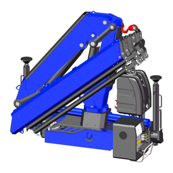
USER MANUAL 910NG B.3.4 MAIN COMPONENTS A list of the main crane components is given below in accordance with EN 12999: MAIN COMPONENTS Column boom cylinder boom boom cylinder boom Extension cylinders Hydraulic extensions Stabilizer cylinder Stabilizer extension Oil tank... -
Page 37: Controls
USER MANUAL 910NG CONTROLS B.4.1 CONTROL STATIONS NO RDC-CRANE On main control valve side For NO CE only. 7845473-01 03/20 subject to change without notice... - Page 38 USER MANUAL 910NG NO RDC-CRANE On opposite control valve side For NO CE only. 7845473-01 03/20 subject to change without notice...
- Page 39 USER MANUAL 910NG RDC-CRANE EMERGENCY CONTROLS WITH DISPLAY On the main control valve side 7845473-01 03/20 subject to change without notice...
- Page 40 USER MANUAL 910NG RDC-CRANE EMERGENCY CONTROLS WITHOUT DISPLAY On the main control valve side In case of work lights only. 7845473-01 03/20 subject to change without notice...
- Page 41 USER MANUAL 910NG RDC-CRANE EMERGENCY CONTROLS On opposite main control valve side 7845473-01 03/20 B.10 subject to change without notice...
-
Page 42: Description Of Controls
USER MANUAL 910NG B.4.2 DESCRIPTION OF CONTROLS FLOW DEVIATION LEVER (NO CE, NO RDC) • Lever UP: crane enabled, stabilizers disabled • Lever DOWN: crane disabled, stabilizers enabled KEY SWITCH SELECTOR (RDC, NO TOP) Stabilizers controls enabled Crane controls disabled... -
Page 43: Outriggers Controls (Optional)
USER MANUAL 910NG STABILIZERS CONTROLS ON THE MAIN CONTROL VALVE SIDE ON THE OPPOSITE MAIN CONTROL VALVE SIDE Stabilizer extension Stabilizer extension on the side where the on the side where the option option operator is working operator is working... -
Page 44: Emergency Controls
USER MANUAL 910NG B.4.5 EMERGENCY CONTROLS In case of failure, the operator can pass manually from the crane controls to the stabilizer controls and vice versa following the procedures below. CE, NO RDC CRANE Break the seal sticker, push and turn the manual actuator. Then screw the knurled knob under the main control valve (see figure below). -
Page 45: Safety Devices
USER MANUAL 910NG SAFETY DEVICES B.5.1 OVERCENTER VALVES The overcenter valves are fitted on the 1 boom cylinder and on the 2 boom cylinder. Their purpose is to lower or block the load if the pressure into the cylinders reaches the setting value. So the crane structure is made safe. -
Page 46: Moment Limiter
USER MANUAL 910NG B.5.3 MOMENT LIMITER The purpose of the moment limiter is to protect the crane's structure from overload and ensure machine stability. It constantly detects the pressure in the 1st boom cylinder and intervenes when the lifting moment exceeds the setting value. -
Page 47: Locking Devices For Stabilizer Extensions
USER MANUAL 910NG B.5.5 LOCKING DEVICES FOR STABILIZER EXTENSIONS FOR ALL CRANE VERSIONS On both sides of the base an automatic lock is installed. Its purpose is to lock automatically the stabilizer extension in its fully closed position. To release the extension and pull it out, it’s necessary to pull the automatic lock and pull out the extension with the... -
Page 48: Locking Device For Turning Stabilizer Legs
USER MANUAL 910NG B.5.6 LOCKING DEVICE FOR TURNING STABILIZER LEGS Their purpose is to lock the rotation of the stabilizer legs in working and transport position. LOCKING DEVICE WITH LEVER FOR MANUAL TURNING STABILIZERS Locking pin Rotating lever Failure to lock the stabilizer legs correctly when transporting the machine may cause damage to property and injury to people. -
Page 49: Locking Device For Manual Extensions
USER MANUAL 910NG B.5.8 LOCKING DEVICE FOR MANUAL EXTENSIONS Two locking plates are mounted at the end of the last hydraulic extension to prevent the accidental removal of the manual extension. Fixing screws Locking plate Manual extension The plates allow the manual extension to slide freely between the fully retracted and fully extended position. -
Page 50: Gauges And Indicators
USER MANUAL 910NG GAUGES AND INDICATORS B.6.1 GAUGES ON OIL TANK OIL LEVEL INDICATORS The oil tank is fitted with two visual level indicators in order to check the amount of oil in the tank. Maximum level Minimum level THERMOMETER CE cranes are fitted with a thermometer that shows the current oil temperature in degrees Celsius: •... -
Page 51: Load Indicators
USER MANUAL 910NG CLOGGING INDICATOR The CE tank filter and the high pressure filter (option) have clogging indicators that indicate when the filter cartridge has to be replaced (pressure gauge on red). RDC-cranes are always equipped with high pressure filter and clogging indicators. -
Page 52: Level Indicator
USER MANUAL 910NG PRESSURE GAUGES (OPTION FOR NO CE) The pressure gauges indicate the pressure of the 1.boom cylinder. • Green sector: 90% of lifting capacity is not reached • Yellow sector: 90% of lifting capacity is reached • Red sector: 100% of lifting capacity is reached B.6.3... -
Page 53: Operating Hours Counter (No Ce, No Top)
USER MANUAL 910NG B.6.4 OPERATING HOURS COUNTER (NO CE, NO TOP) The hours counter is installed at the control station on the main control valve side. Purpose of the counter is to indicate the total operating hours of the crane: the user shall perform the planned maintenance at the intervals shown in the Maintenance Record (see C.3). -
Page 54: Operating The Crane
USER MANUAL 910NG OPERATING THE CRANE B.7.1 PRELIMINARY CHECKS BEFORE OPERATION Before using the crane check that - crane's structure, safety devices and safety signs are intact. - there are no parts on the equipment which have not been checked or are not permitted. -
Page 55: How To Deploy The Stabilizers With Manually Operated Extensions
USER MANUAL 910NG B.7.3 HOW TO DEPLOY THE STABILIZERS WITH MANUALLY OPERATED EXTENSIONS LOCKING DEVICES OF STABILIZER EXTENSIONS Automatic lock Lock support Semi-automatic locking device Lever 3 up: the locking device 1 is engaged or ready to get engaged Lever 3 down: the locking device 1 in disengaged Operating the crane is allowed only when the stabilizers are deployed correctly. - Page 56 USER MANUAL 910NG 2) Lower the automatic lock 1, rotate and lay the lock support 2 on the pin. 3) Pull the suitable handle and extract completely the stabilizer extension till the semi-automatic locking device 3 does stop the beam extension, then shake it to be sure the locking device 3 is fully engaged.
- Page 57 USER MANUAL 910NG 4) If the crane is fitted with turning stabilizer legs, rotate downwards the leg up to the vertical position (see B.7.5) 5) Extend the cylinder till to place the foot on the ground, without fully discharging the vehicle's suspension.
-
Page 58: How To Deploy The Stabilizers With Hydraulically Operated Extensions
USER MANUAL 910NG B.7.4 HOW TO DEPLOY THE STABILIZERS WITH HYDRAULICALLY OPERATED EXTENSIONS LOCKING DEVICE OF STABILIZER EXTENSIONS Automatic lock Lock support Operating the crane is allowed only when the stabilizers are deployed correctly. Always use the controls on the side on which you are operating the crane. - Page 59 USER MANUAL 910NG 2) Lower the automatic lock 1, rotate and lay the lock support 2 on the pin. 3) By using the control lever below extract the stabilizer extension. The yellow warning sign on extension appears, if the extension is fully extracted.
- Page 60 USER MANUAL 910NG 4) If the crane is fitted with turning stabilizer legs, rotate downwards the leg up to the vertical position (see B.7.5) 5) Extend the cylinder till to place the foot on the ground, without fully discharging the vehicle's suspension.
-
Page 61: How To Rotate Downwards The Manual Turning Stabilizer Legs
USER MANUAL 910NG B.7.5 HOW TO ROTATE DOWNWARDS THE MANUAL TURNING STABILIZER LEGS LOCKING DEVICE OF TURNING LEGS Locking device with lever Lever 1 perpendicular to extension axis (down): the locking device is engaged Lever 1 parallel to extension axis (up): the locking device is disengaged Execute the following procedure: 1) Grasp the handle and turn counter-clockwise the lever (the locking device is disengaged). - Page 62 USER MANUAL 910NG 2) Rotate slightly the leg, holding the locking device 1 in disengaged state. 3) Then release the locking lever and rotate fully the leg downwards up to the vertical position: the locking device engages automatically (the lever turns clockwise and goes down). If the locking device doesn't engage, shake lightly the leg.
-
Page 63: Opening Procedure
USER MANUAL 910NG B.7.6 OPENING PROCEDURE 1) If the crane is in folded position, fully retract the 2nd boom cylinder (articulation cylinder). 2) Lift the 1st boom so that the 2nd boom can rotate freely. 3) Move the 2nd boom to the horizontal position. -
Page 64: How To Read The Load Chart
USER MANUAL 910NG B.7.7 HOW TO READ THE LOAD CHART Fmax= 7370 daN The load chart shows the rated loads (kg) that the crane can lift depending on working radius (m). The load chart applied on the crane shows the rated loads for the crane with horizontal booms; the chart showing the whole working range is given in the Technical Sheet. -
Page 65: Closing Procedure
USER MANUAL 910NG B.7.9 CLOSING PROCEDURE The operator should close the crane from the column side to avoid collisions with moving parts of the crane. 1) Close the hydraulic extensions of the crane 2) Move the 1st boom so that the 2nd boom can rotate freely. - Page 66 USER MANUAL 910NG 4) Close the 2nd boom completely, operating the control lever of the articulation cylinder. 5) Lower the 1st boom until the recovery locks are in their seats. Block the crane. If, for transport, the crane is closed with the boom on the vehicle body, make sure that the crane cannot move.
-
Page 67: How To Fold The Stabilizers With Manually Operated Extensions
USER MANUAL 910NG B.7.10 HOW TO FOLD THE STABILIZERS WITH MANUALLY OPERATED EXTENSIONS LOCKING DEVICES OF STABILIZER EXTENSIONS Automatic lock Lock support Semi-automatic locking device Lever 3 up: the locking device 1 is engaged or ready to get engaged Lever 3 down: the locking device 1 in disengaged The stabilizers can be closed exclusively after the booms are closed in transport position. - Page 68 USER MANUAL 910NG 2) If the crane is fitted with turning stabilizer legs, rotate the leg up to its transport position (see B.7.12) 3) Turn the lever 3 downwards up to its vertical locking position: the locking device is disengaged.
-
Page 69: How To Fold The Stabilizers With Hydraulically Operated Extensions
USER MANUAL 910NG B.7.11 HOW TO FOLD THE STABILIZERS WITH HYDRAULICALLY OPERATED EXTENSIONS LOCKING DEVICE OF STABILIZER EXTENSIONS Automatic lock Lock support The stabilizers can be closed exclusively after the booms are closed in transport position. Always use the controls on the side on which you are operating the crane. - Page 70 USER MANUAL 910NG 3) Retract fully the stabilizer extension. The automatic lock 1 engages automatically. 7845473-01 03/20 B.39 subject to change without notice...
-
Page 71: How To Rotate Upwards The Manual Turning Stabilizer Legs
USER MANUAL 910NG B.7.12 HOW TO ROTATE UPWARDS THE MANUAL TURNING STABILIZER LEGS LOCKING DEVICE OF TURNING LEGS Locking device with lever Lever 1 perpendicular to extension axis (down): the locking device is engaged Lever 1 parallel to extension axis (up): the locking device is disengaged Execute the following procedure: 1) Grasp the handle and turn clockwise the lever (the locking device is disengaged). - Page 72 USER MANUAL 910NG 2) Rotate slightly the leg, holding the locking device 1 in disengaged state. 3) Then release the locking lever and rotate fully the leg upwards up to the vertical position: the locking device engages automatically (the lever turns clockwise and goes down). If the locking device doesn't engage, shake lightly the leg.
-
Page 73: Use With Manual Extensions
USER MANUAL 910NG B.7.13 USE WITH MANUAL EXTENSIONS The manual extensions can be used only with the hook to increase the crane's outreach. The maximum capacity of each manual extension is constant (see A.14), indicated in the load chart and marked on a plate applied on the extension itself. -
Page 74: Use With Bucket-Grab
USER MANUAL 910NG B.7.14 USE WITH BUCKET-GRAB The bucket can only be operated when the crane opening procedure is complete. The control is used to open and close the bucket thus allowing to lift and release the load. The bucket is often secured to a hydraulic rotor that allows to rotate on its own axis. There is a separate control for this. -
Page 75: Use Under Special Service Conditions
USER MANUAL 910NG USE UNDER SPECIAL SERVICE CONDITIONS Exceptionally, the crane can be operated even if the service conditions are not met, i.e when: - the stabilizers feet are deployed on a soft surface - the crane is operated in low-temperature environments - the inclination angle of the crane's base exceeds the max. -
Page 76: Low-Temperature Environments
USER MANUAL 910NG B.8.2 LOW-TEMPERATURE ENVIRONMENTS The crane is designed to withstand the maximum stresses when the environmental temperature is within the range given in B.3.3. When the environmental temperature is below the allowable range, then a derating factor shall be applied to the max. working pressure, as follows: = κ... -
Page 77: In-Service Wind
USER MANUAL 910NG B.8.4 IN-SERVICE WIND The crane is designed to withstand occasionals loads due to the wind effects. According to EN 13001-2, the crane can be safely operated under the following wind state: - Wind state: Light - Max. mean wind speed: v = 9.4 m/s (34 km/h, 5 Beaufort) If the wind speed should exceed the limit above, then a derating factor shall be applied to the max. - Page 78 USER MANUAL 910NG The following table shows the Beafort scale and its wind speed ranges. BEAUFORT SCALE Wind speed Beaufort Wind Symbol Effect force km/h Calm 0 - 0.2 0 - 1 Smoke rises vertically Light air 0.3 - 1.5...
-
Page 79: Maintenance
USER MANUAL 910NG AINTENANCE MAINTENANCE WARRANTY TERMS The manufacturer declines all responsibility for damage to the crane caused by failed maintenance or lubrication. Preventive routine maintenance refers to machine use in non-abrasive and non- corrosive environments. Failure to abide by this stipulation shall result in all guarantees for faults being declared null and void. - Page 80 USER MANUAL 910NG AINTENANCE GREASING CHART Manual greasing of boom extensions' sliding surfaces Frequency of greasing: 200 working hours / 180 days Manual greasing of stabilizer extensions' sliding surfaces Frequency of greasing: 100 working hours / 90 days Greasing under pressure of nipples...
-
Page 81: Filling Up The Oil Tank
USER MANUAL 910NG AINTENANCE C.2.2 FILLING UP THE OIL TANK Before using the crane, check the oil level in the tank: the level with horizontal crane at rest, must always be between the minimum and maximum level. If the level is under the minimum, fill up the tank. -
Page 82: Planned And Extraordinary Maintenance
USER MANUAL 910NG AINTENANCE PLANNED AND EXTRAORDINARY MAINTENANCE The owner of the crane is responsible for contacting an authorised assistance centre to perform the following maintenance activities: - planned maintenance - maintenance after inactivity - extraordinary maintenance All maintenance activities are scheduled and must be registered in the Maintenance Record: the maintenance schedule must be signed by the authorised assistance centre. -
Page 83: Technical Sheet
USER MANUAL 910NG ECHNICAL HEET TECHNICAL SHEET 7845473-01 03/20 subject to change without notice... -
Page 84: Crane's Technical Data
USER MANUAL 910NG ECHNICAL HEET CRANE'S TECHNICAL DATA Versions Max. net lifting moment 87.4 84.0 81.7 78.7 73.4 10940 daNm Max. dynamic moment Capacity at min. hook [S2] 2125 2055 1960 1850 1700 hydraulic outreach grab [S1] 2125 2055 1960... -
Page 85: Winch Settings
USER MANUAL 910NG ECHNICAL HEET WINCH SETTINGS TI1 - SINGLE LINE PULL Versions Max line pull 1000 1000 1000 1000 1000 (*) Start angle - pull% 75°-82% Final angle - pull% 60°-85% N/A: configuration not available (*): configuration requiring pull derating: available only for CE/TOP cranes (PCS) Pull%: pull derating percentage When the crane is equipped with winch, the max. -
Page 86: Overall Dimensions
USER MANUAL 910NG ECHNICAL HEET OVERALL DIMENSIONS FIXED STABILIZERS LEGS 2290 266.5 Ø160 30° 160.5 2110 2270 3290 ST 4790 EX W (*) 5755 SE W+ (*) EXTRA FUNCTION W (*) (mm) Compact W+ (*) (mm) Slides Hose reel (*) The width has to be decreased by 40 mm in case of ST stabilisers. -
Page 87: Base Dimensions And Mounting Bolts
USER MANUAL 910NG ECHNICAL HEET BASE DIMENSIONS AND MOUNTING BOLTS 1086 1090 1926 Material Tightening Ref. Description Q.ty Size Grade torque Kit with 8 42CrMo4+QT M20x1.5 250 Nm crane mounting bolts EN 10083-3 L=900 Kit with 4 39NiCrMo3+QT M24X2 400 Nm... -
Page 88: Installation Type Number
USER MANUAL 910NG ECHNICAL HEET INSTALLATION TYPE NUMBER Installation types numbers (ITN) for cranes with standard dead point (STOP) toward swivel bridge. OPPOSITE DEAD POINT STANDARD DEAD POINT STOP STOP STOP STOP STOP STOP STOP STOP STOP STOP STOP STOP... -
Page 89: Lifting Height Close To The Column
USER MANUAL 910NG ECHNICAL HEET LIFTING HEIGHT CLOSE TO THE COLUMN 1000 Version 1636 1545 1467 1384 1302 7845473-01 03/20 subject to change without notice... -
Page 90: Load Charts For Use With Hook/Tool
USER MANUAL 910NG ECHNICAL HEET LOAD CHARTS FOR USE WITH HOOK/TOOL 910NG 1S 15° 2125 1490 2125 1490 4.17 5.98 100% If an additional lifting tool is mounted, the rated capacities shall be reduced by the tool's weight 7845473-01 03/20... - Page 91 USER MANUAL 910NG ECHNICAL HEET LOAD CHARTS FOR USE WITH HOOK/TOOL 910NG 2S 15.1 13.1 10.9 15° 2055 1415 1080 2055 1080 1415 4.17 7.79 11.85 5.98 9.82 100% (*) Manual extensions (optional): these cannot lift additional hydraulic tools If an additional lifting tool is mounted, the rated capacities shall be reduced by the tool's weight...
- Page 92 USER MANUAL 910NG ECHNICAL HEET LOAD CHARTS FOR USE WITH HOOK/TOOL 910NG 3S 17.3 15.2 13.1 15° 1960 1320 1960 1320 4.25 6.06 7.87 9.82 11.85 14.00 100% (*) Manual extensions (optional): these cannot lift additional hydraulic tools If an additional lifting tool is mounted, the rated capacities shall be reduced by the tool's weight 7845473-01 03/20 D.10...
- Page 93 USER MANUAL 910NG ECHNICAL HEET LOAD CHARTS FOR USE WITH HOOK/TOOL 910NG 4S 19.5 17.0 15.1 15° 1850 1220 1850 1220 4.33 6.14 7.95 9.90 11.85 14.00 16.18 100% (*) Manual extensions (optional): these cannot lift additional hydraulic tools If an additional lifting tool is mounted, the rated capacities shall be reduced by the tool's weight 7845473-01 03/20 D.11...
- Page 94 USER MANUAL 910NG ECHNICAL HEET LOAD CHARTS FOR USE WITH HOOK/TOOL 910NG 5S 19.5 17.3 15° 1700 1100 1700 1100 4.40 6.21 8.02 9.97 11.92 14.00 16.18 100% (*) Manual extensions (optional): these cannot lift additional hydraulic tools If an additional lifting tool is mounted, the rated capacities shall be reduced by the tool's weight 7845473-01 03/20 D.12...
-
Page 95: Load Charts For Ti1 Winch In Single Line
USER MANUAL 910NG ECHNICAL HEET LOAD CHARTS FOR TI1 WINCH IN SINGLE LINE 910NG 1S + TI1 SINGLE LINE 75° 1000 2.9m (**) 1000 5.98 100% (**) Minimum distance winch - pulley Winch max. pull: 1000 kg 7845473-01 03/20 D.13... - Page 96 USER MANUAL 910NG ECHNICAL HEET LOAD CHART FOR WINCH TI1 IN SINGLE LINE 910NG 2S + TI1 SINGLE LINE 75° 1000 2.9m (**) 1000 7.79 100% (**) Minimum distance winch - pulley Winch max. pull: 1000 kg 7845473-01 03/20 D.14...
- Page 97 USER MANUAL 910NG ECHNICAL HEET LOAD CHART FOR WINCH TI1 IN SINGLE LINE 910NG 3S + TI1 SINGLE LINE 75° 1000 2.9m (**) 1000 7.81 7.87 9.82 100% (**) Minimum distance winch - pulley Winch max. pull: 1000 kg 7845473-01 03/20 D.15...
- Page 98 USER MANUAL 910NG ECHNICAL HEET LOAD CHART FOR WINCH TI1 IN SINGLE LINE 910NG 4S + TI1 SINGLE LINE 75° 1000 2.9m (**) 1000 7.22 7.95 11.85 9.90 100% (**) Minimum distance winch - pulley Winch max. pull: 1000 kg 7845473-01 03/20 D.16...
- Page 99 USER MANUAL 910NG ECHNICAL HEET LOAD CHART FOR WINCH TI1 IN SINGLE LINE 910NG 5S + TI1 SINGLE LINE 75° 60° 2.9m (**) 1000 6.71 8.02 9.97 11.92 14.00 100% (**) Minimum distance winch - pulley Winch max. pull: 1000 kg 7845473-01 03/20 D.17...
-
Page 100: Centers Of Gravity And Test Loads
USER MANUAL 910NG ECHNICAL HEET D.10 CENTERS OF GRAVITY AND TEST LOADS This annex contains the data needed for the stability test in accordance with EN 12999. Loads and centers of gravity Gout Pout Hooking point for the test load... -
Page 101: Hook Data
USER MANUAL 910NG ECHNICAL HEET D.11 HOOK DATA HOOK MOUNTED ON STANDARD BOOM VERSIONS: 1S, 2S, 3S, 4S, 5S DIMENSIONS TECHNICAL PROPERTIES Working load limit (WLL) : 5400 kg Material: alloy steel Weight: 3.2 kg Swivel hook Reference standard: DIN 15401 7845473-01 03/20 D.19... -
Page 102: Load Attachment
USER MANUAL 910NG ECHNICAL HEET D.12 LOAD ATTACHMENT ATTACHMENT FOR HOOK R 30 7845473-01 03/20 D.20 subject to change without notice... -
Page 103: Hydraulic System
USER MANUAL 910NG ECHNICAL HEET D.13 HYDRAULIC SYSTEM FITTINGS FOR CONNECTION TO PUMP 910NG NO RDC Control valve M 7/8"-14 M 3/4"-16 pressure line Tank M 1"1/2 M 1" 1/2 suction line EXTENSION TIMES OF HYDRAULIC CYLINDERS Extension time Retraction time 910NG Slewing (180°) - Page 104 USER MANUAL 910NG ECHNICAL HEET CAPACITY OF HYDRAULIC SYSTEM Cylinders extended Cylinders retracted 910NG ℓ ℓ Capacities do not include the oil tank. ADDITIONAL CAPACITY FOR HYDRAULICALLY OPERATED STABILIZER EXTENSIONS EX-H +3.5 +2.0 SE-H +4.5 +3.0 7845473-01 03/20 D.22 subject to change without notice...
-
Page 105: Oil Cooler
USER MANUAL 910NG ECHNICAL HEET D.14 OIL COOLER TECHNICAL SPECIFICATIONS Heat transfer coefficient: 235 W/K (oil flow rate of 40 ℓ/min) Activation temperature: 48 °C Weight: 13.5 kg Capacity: 4 ℓ For a crane without oil cooler performing a sequence of standard work cycles, the difference in temperature between the oil and the environment is shown in the graph below. - Page 106 USER MANUAL 910NG ECHNICAL HEET However, when a crane equipped with oil cooler carries out a sequence of standard work cycles, the oil temperature exceeds 75 °C after the following working times: to exceed 75 °C τ (°C) (minutes) no limit...
-
Page 107: Additional Stabilizers
USER MANUAL 910NG ECHNICAL HEET D.15 ADDITIONAL STABILIZERS Additional stabilizers must be chosen so that: - the installation is stable (see Installer Manual) - the max. force acting on the additional stabilizers, F , is lower than the max. load allowed by the stabilizers itself, R ≥... -
Page 108: Recommended Additional Lifting Tools
USER MANUAL 910NG ECHNICAL HEET D.16 RECOMMENDED ADDITIONAL LIFTING TOOLS CLAMSHELL BUCKET Data of recommended tool Load ratio Crane Gross load Payload version HYVA weight volume capacity crane tool model 1490 H605-550 1115 100% 1080 H605-450 100% H605-250 100% H604-200... - Page 109 USER MANUAL 910NG ECHNICAL HEET RECOMMENDED ADDITIONAL LIFTING TOOLS ORANGE PEEL GRAPPLE Data of recommended tool Load ratio Crane Gross load Payload version HYVA weight volume capacity crane tool model H653-4 1490 1055 100% large H653-4 1080 100% large H652-5...
- Page 110 USER MANUAL 910NG ECHNICAL HEET RECOMMENDED ADDITIONAL LIFTING TOOLS LOGGING GRAPPLE Data of recommended tool Load ratio Crane Gross load Payload version HYVA weight capacity crane tool model 1490 H634-0,25 4000 1320 100% 1080 H634-0,25 4000 100% H634-0,25 4000 100%...
- Page 111 USER MANUAL 910NG ECHNICAL HEET RECOMMENDED ADDITIONAL LIFTING TOOLS BRICK STACK GRAPPLE Data of recommended tool Load ratio Crane Gross load Payload version HYVA weight capacity crane tool model 1225 1490 H332-1330 1600 100% 1080 H332-1330 1600 100% H332-1330 1600...
- Page 112 USER MANUAL 910NG ECHNICAL HEET RECOMMENDED ADDITIONAL LIFTING TOOLS PALLET FORK Data of recommended tool Load ratio Crane Gross load Payload version HYVA weight capacity crane tool model H415 1490 2000 1335 100% 2000-500 H415 1080 2000 100% 2000-500 H415...
-
Page 113: Annexes
USER MANUAL 910NG NNEXES ANNEXES HYDRAULIC SCHEMATICS STABILIZERS MANUALLY OPERATED EXTENSIONS 1040041 Settings = 100 bar 7845473-01 03/20 subject to change without notice... - Page 114 USER MANUAL 910NG NNEXES HYDRAULIC SCHEMATICS STABILIZERS HYDRAULICALLY OPERATED EXTENSIONS FIXED OR MANUALLY TURNING STABILIZER LEGS 1040047 Settings = 100 bar 7845473-01 03/20 subject to change without notice...
- Page 115 USER MANUAL 910NG NNEXES HYDRAULIC SCHEMATICS ADDITIONAL STABILIZERS MANUALLY OPERATED EXTENSIONS CRANE'S STABILIZERS CONTROL VALVE CARRY-OVER 1040043 Settings = 100 bar 7845473-01 03/20 subject to change without notice...
- Page 116 USER MANUAL 910NG NNEXES HYDRAULIC SCHEMATICS ADDITIONAL STABILIZERS HYDRAULICALLY OPERATED EXTENSIONS CRANE'S STABILIZERS CONTROL VALVE CARRY-OVER 1040048 Settings = 100 bar 7845473-01 03/20 subject to change without notice...
- Page 117 USER MANUAL 910NG NNEXES HYDRAULIC SCHEMATICS CONTROL VALVES NO RDC - NO CE 25µ 1.7 bar 1030225 Settings q = 20 ℓ/min = 335 bar for 1S - 2S - 3S = 330 bar for 4S - 5S [p] = 280 bar [q] = 10 ℓ/min...
- Page 118 USER MANUAL 910NG NNEXES HYDRAULIC SCHEMATICS CONTROL VALVES NO RDC - CE 25µ 1.7 bar 1030226 Settings q = 20 ℓ/min = 335 bar for 1S - 2S - 3S = 330 bar for 4S - 5S [p] = 280 bar [q] = 10 ℓ/min...
- Page 119 USER MANUAL 910NG NNEXES HYDRAULIC SCHEMATICS SUPPLEMENTARY ACTIVATION ELEMENTS NO RDC 1030194 Settings for winch Settings for rotor und bucket/grab = 200 bar = 200 bar = 200 bar = 200 bar = 200 bar = 200 bar 7845473-01 03/20...
- Page 120 USER MANUAL 910NG NNEXES HYDRAULIC SCHEMATICS CONTROL VALVE RDC - NO CE HPCO 25µ 10µ 1.7 bar 6 bar 1030198 Settings q = 40 ℓ/min = 335 bar for 1S - 2S - 3S = 330 bar for 4S - 5S [p] = 280 bar [q] = 10 ℓ/min...
- Page 121 USER MANUAL 910NG NNEXES HYDRAULIC SCHEMATICS SUPPLEMENTARY ACTIVATION ELEMENTS RDC - NO CE 1030199 Settings for winch Settings for rotor und bucket/grab = 200 bar = 200 bar = 200 bar = 200 bar = 200 bar = 200 bar...
- Page 122 USER MANUAL 910NG NNEXES HYDRAULIC SCHEMATICS CONTROL VALVE RDC - CE HPCO 25µ 10µ 1.7 bar 6 bar 1030196 Settings q = 40 ℓ/min = 335 bar for 1S - 2S - 3S = 330 bar for 4S - 5S [p] = 280 bar [q] = 10 ℓ/min...
- Page 123 USER MANUAL 910NG NNEXES HYDRAULIC SCHEMATICS SUPPLEMENTARY ACTIVATION ELEMENTS RDC - CE 1030197 Settings for winch Settings for rotor und bucket/grab = 200 bar = 200 bar = 200 bar = 200 bar = 200 bar = 200 bar 7845473-01 03/20 E.11...
- Page 124 USER MANUAL 910NG NNEXES HYDRAULIC SCHEMATICS CONTROL VALVE FOR LS VARIABLE DISPLACEMENT PUMP RDC - CE HPCO 25µ 10µ pump 1.7 bar 6 bar 1030238 Special settings q : variabel = 365 bar for 1S - 2S - 3S = 360 bar...
- Page 125 USER MANUAL 910NG NNEXES HYDRAULIC SCHEMATICS OIL COOLER (OPTION) 1030250 7845473-01 03/20 E.13 subject to change without notice...
- Page 126 USER MANUAL 910NG NNEXES HYDRAULIC SCHEMATICS SLEWING SYSTEM 1050102 Rack stroke : 625 mm Settings = 190 bar 7845473-01 03/20 E.14 subject to change without notice...
- Page 127 USER MANUAL 910NG NNEXES HYDRAULIC SCHEMATICS BOOM CYLINDER set3 set1 set2 1050093 Settings = - bar for 1S - 2S set1 = 380 bar for 3S set1 = 365 bar for 4S set1 = 350 bar for 5S set1 = 32 bar...
- Page 128 USER MANUAL 910NG NNEXES HYDRAULIC SCHEMATICS BOOM CYLINDER set2 set1 1050119 Settings = - bar for 1S - 2S set1 = 350 bar for 3S set1 = 335 bar for 4S - 5S set1 = 315 bar set2 7845473-01 03/20 E.16...
- Page 129 USER MANUAL 910NG NNEXES HYDRAULIC SCHEMATICS EXTENSION CYLINDERS 5° 4° 3° 2° 1° set2 set1 1050103 Settings = 210 bar set1 = 430 bar set2 7845473-01 03/20 E.17 subject to change without notice...
- Page 130 USER MANUAL 910NG NNEXES HYDRAULIC SCHEMATICS MOMENT LIMITER, NO RDC - NO CE Option 5 bar 1060093 Settings = 330 bar for 1S - 2S - 3S = 325 bar for 4S = 320 bar for 5S 7845473-01 03/20 E.18...
-
Page 131: Electric Schematics
USER MANUAL 910NG NNEXES ELECTRIC SCHEMATICS TECHNICAL DATA Supply voltage 12V - 24V Max. current absorbed by the electric system Max. current absorbed by the electric system with radio-controlled stabilizers Environment working temperature -35°C ÷ 85°C IP protection class IP 66 7845473-01 03/20 E.19... - Page 132 USER MANUAL 910NG NNEXES ELECTRIC SCHEMATICS EMERGENCY STOP BUTTONS NO RDC - NO CE (OPTION) 1010225 7845473-01 03/20 E.20 subject to change without notice...
- Page 133 USER MANUAL 910NG NNEXES ELECTRIC SCHEMATICS TERMINAL BOX - ELECTRIC SCHEMATIC DEV. DANFOSS WINCH OUT WINCH PWR RELE' DISP. OPTION-RDC OUT OPTION-RDC IN SERVICE RDC PWR RDC 1010244-P1 7845473-01 03/20 E.21 subject to change without notice...
- Page 134 USER MANUAL 910NG NNEXES ELECTRIC SCHEMATICS TERMINAL BOX - CONNECTIONS 64 65 66 67 68 RELE' DISP. 69 70 71 72 73 74 75 76 0PTON RADIO OUT 77 78 79 80 81 82 83 84 OPTION RADIO IN 1010244-P2 7845473-01 03/20 E.22...
- Page 135 USER MANUAL 910NG NNEXES ELECTRIC SCHEMATICS NO CE - FULL OPTIONAL KEY SWITCH 2ND BOOM EXT. 1ST BOOM SLEWING 1 2 3 4 SERVICE 8 EL. 7 EL. 6 EL. 5 EL. 1010244-P3_MAUM 7845473-01 03/20 E.23 subject to change without notice...
- Page 136 USER MANUAL 910NG NNEXES ELECTRIC DIAGRAM AVPS SYSTEM NOT-RDC / NO CE CRANE POWER SERVICE EMERG.2 SUPPLY 22 23 24 25 CRANE EV LCS AVPS PRESS. TERMINAL BOX CRANE PRESS. EV LCS EV AVPS 1010244-P1 / P3_MAUM Settings q = 10 ℓ/min 7845473-01 03/20 E.24...
- Page 137 USER MANUAL 910NG NNEXES ELECTRIC SCHEMATICS NO CE - RADIO CONTROL WIRING LAY-OUT CAN cable SERVICE cable POWER cable BU (GNYE) BK (1) RD (2) BU (GNYE) BK (1) RD (2) BU (GNYE) BK (1) RD (2) BU (GNYE) BK (1)
-
Page 138: Safety Signs
USER MANUAL 910NG NNEXES SAFETY SIGNS Sign Position Description Do NOT bang against the On stabilizer legs stabilisers during the stabilization of the crane Do not position lower limbs On stabilizer legs under stabiliser legs during the stabilization of the crane... - Page 139 USER MANUAL 910NG NNEXES SAFETY SIGNS Sign Position Description Read the user manual Wear helmet, gloves, industrial footwear At controls Warning: do NOT bang on the booms during opening and folding of the crane Seal sticker Do NOT use emergency controls under...
- Page 140 USER MANUAL 910NG NNEXES LOCATION OF SAFETY SIGNS 7845473-01 03/20 E.28 subject to change without notice...
-
Page 141: Tightening Torques
USER MANUAL 910NG NNEXES TIGHTENING TORQUES SCREWS - BOLTS TIGHTENING TORQUE Property class THREAD DIAMETER 10.9 12.9 (mm) M 6 x 1 16.4 M 8 x 1.25 M 10 x 1.5 M 12 x 1.75 M 14 x 2 M 16 x 2 M 18 x 2.5... -
Page 142: Selection Of The Hydraulic Oil
USER MANUAL 910NG NNEXES SELECTION OF THE HYDRAULIC OIL Viscosity is one of the most important properties of hydraulic oils because it affects the hydraulic sealing and the functionality of the safety valves. Therefore the oil temperature is very important because even small changes in temperature affect its viscosity: as the temperature increases, viscosity decreases. -
Page 143: Locking Device For Swivel Bridge
USER MANUAL 910NG NNEXES LOCKING DEVICE FOR SWIVEL BRIDGE When selling the crane, the swivel bridge is locked by means of a rotation locking device. The swivel lock consists of a device equipped with locking pins that prevent the bridge rotation with respect to the base. -
Page 144: Troubleshooting
USER MANUAL 910NG NNEXES TROUBLESHOOTING Trouble Possible causes Troubleshooting The crane decreases in Check the pressure on the pump efficiency, the oil temperature delivery. If it’s necessary to increases, it is necessary to Pump wear replace it, go to an authorized... - Page 145 USER MANUAL 910NG NNEXES TROUBLESHOOTING Trouble Possible causes Troubleshooting 1) The block valve on the The stabilizer leg closes during stabilizer leg worn, no more 1-2) Go to an authorized the crane work. seal. assistance center. 2) Internal seals wear.
-
Page 146: Ec Declaration Of Conformity
USER MANUAL 910NG NNEXES EC DECLARATION OF CONFORMITY 7845473-01 03/20 E.34 subject to change without notice...
Need help?
Do you have a question about the 910NG and is the answer not in the manual?
Questions and answers