Table of Contents
Advertisement
Quick Links
Advertisement
Table of Contents

Related Manuals for Sena Parani-ESD210


Summary of Contents for Sena Parani-ESD210
- Page 1 Parani-ESD100/110/200/210 User Guide Version 1.0.0 2006-08-14...
- Page 2 This device is not approved for life-support or medical systems. Changes or modifications to this device not explicitly approved by Sena Technologies will void the user's authority to operate this device.
-
Page 3: Table Of Contents
Contents 1. Introduction 1.1. Overview ........................... 6 1.2. Package Check List ........................6 1.3. Product Specification........................7 2. Getting Started 2.1. Panel Layout ..........................8 2.2. Connecting the Hardware ......................8 2.2.1. Connecting Parani-ESD to Jig Board ................9 2.2.2. Connecting Power to Jig Board ..................9 2.2.3. - Page 4 B.3.1. ATZ ..........................33 B.3.2. AT&F ..........................33 B.3.3. AT ..........................33 B.3.4. AT+UARTCONFIG,Baudrate,Parity,Stopbit,Hwfc ............33 B.3.5. AT+USEDIP? ....................... 34 B.3.6. AT+BTINFO? ....................... 34 B.3.7. AT+BTINQ? ........................34 B.3.8. AT+BTLAST? ....................... 34 B.3.9. AT+BTVER? ........................ 35 B.3.10. AT+BTRSSI,n ......................35 B.3.11.
- Page 5 D.2.2 SD Response ......................... 46 D.3 Transmission Delay ........................47 D.3.1 RF Processing Delay......................47 D.3.2 RF Transmission Environment ..................47 Appendix E: How make a RS232 interface Jig Board...
-
Page 6: Introduction
1. Introduction 1.1. Overview Parani-ESD is a module device for wireless serial communication using the Bluetooth technology that is international standard of short range wireless communications. Parani-ESD accomplishes more reliable wireless communication. As Parani-ESD can communicate with other Bluetooth devices, user may construct various communications with it. -
Page 7: Product Specification
1.3. Product Specification ESD100/110 ESD200/210 Serial Interface Serial speeds 1200bps to 230400bps Flow Control: None, Hardware RTS/CTS 2.54mm Header 2X6 2.54mm Header 1X4X2 Bluetooth Interface Bluetooth v1.2 Protocol: RFCOMM, L2CAP, SDP Profile: General Access Profile, Serial Port Profile Class 1 Class 2 Level: 18dBm Level: 2dBm... -
Page 8: Getting Started
2. Getting Started This chapter describes how to set up the Parani-ESD Series for the first time. - 2.1 Panel Layout explains the panel layout. - 2.2 Connecting the Hardware describes how to connect the Parani-ESD Series, the power, and the serial device to the Jig Board. -
Page 9: Connecting Parani-Esd To Jig Board
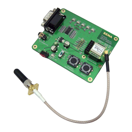
2.2.1. Connecting Parani-ESD to Jig Board Connect the Parani-ESD Series to the Jig Board as shown below. Figure 2-2 Connecting Parani-ESD to Jig Board 2.2.2. Connecting Power to Jig Board Connect the power jack to the power connector of the Jig Board for the Parani-ESD Series using the DC power adapter or USB power cable that is included in the package. -
Page 10: Connecting A Device To Jig Board
2.2.3. Connecting a Device to Jig Board Connect the serial data cable between the Jig Board and the serial device. If necessary, supply the power to the serial device attached to the Jig Board. Figure 2-4 Connecting a Device to Jig Board... -
Page 11: Configuration
3. Configuration 3.1. Operation Modes In addition to the serial port configurations such as bit/second, data bit, parity, stop bit, flow control, Parani-ESD has some configurations for Bluetooth. For getting the most out of Parani-ESD, user should understand the following Bluetooth connection schemes. A Bluetooth device can play a role as a master or slave. -
Page 12: Serial Ports
For large data transmission, use of hardware flow control is highly recommended. 3.2.3. Software and Utility This configuration software and utility for firmware update comes with the product, which also can be downloaded from http://www.sena.com Table 3-3 Configuration Software Software... -
Page 13: Paraniwin
3.2.4. ParaniWIN ParaniWIN is a program running on Microsoft Windows for the configuration of Parani-ESD. Install ParaniWIN on your computer. Plug a Parani-ESD into the serial port of the computer and turn on the power. Run ParaniWIN. Figure 3-1 Serial Port Setting Set each option properly and click [Confirm]. - Page 14 Figure 3-3 Main Window...
- Page 15 Figure 3-4 Information Window Serial port settings can be changed by <Start Configuration> and <ParaniWIN Configuration> of ParaniWIN in the menu bar at upper left corner of the window without re-running the ParaniWIN program. Figure 3-5 Menu Bar at Upper Left corner of ParaniWIN The icons in the left side window come to the corresponding windows.
- Page 16 value. If you check Encryption option, the Parani-ESD encrypts packets and sends them. The Encryption options works well in case that only one between Master and Slave uses this option. Parani-ESD has 4 response messages, ‘OK’, ‘ERROR’, ‘CONNECT’, and ‘DISCONNECT’. In some cases, these responses can affect the host system unexpectedly.
- Page 17 Figure 3-8 Sensitivity Test The sensitivity test shows LInkQuality and RSSI values. The sensitivity is fine, If the LinkQuality is closer to 255 and RSSI is closer to 0. In general, the sensitivity is the best when the distance is 10 meters.
- Page 18 Figure 3-9 Connection(in) Window If the Connection Wizard icon is clicked, an easy pairing menu to use appears as follows: Figure 3-10 Connection Wizard Window...
-
Page 19: Paraniupdater
3.2.5. ParaniUpdater Parani-ESD support firmware update. You can download new firmwares of Parani-ESD at http://www.sena.com. With ParaniUpdater, you can update firmware of Parani-ESD by selecting the firmware image file and pushing Start button. * Note: DO NOT power off Parani-ESD while the firmware update is progressing. It may damage the firmware seriously. - Page 20 Launch HyperTerminal. It can be found in start >programs >accessories >communication >HyperTerminal. Select the Serial port that Parani-ESD will be connected to. Input the same settings into Serial port configuration window as Parani-ESD settings. The settings need to be set correctly, otherwise, error message may be shown up on the screen or cause malfunctioning of Parani-ESD.
-
Page 21: Approval Information
4. Approval Information 4.1. FCC 4.1.1. FCC Compliance Statement This device complies with part 15 of the FCC Rules. Operation is subject to the following two conditions: (1) This device may not cause harmful interference, and (2) This device must accept any interference received, Including interference that may cause undesired operation Information to User This equipment has been tested and found to comply with the limits for a Class B digital device,... -
Page 22: Rf Information
5. RF Information 5.1. Radio Frequency Range 2.402~2.480GHz 5.2. Number of Frequency Channel 79 channels 5.3. Transmission Method FHSS(Frequency Hopping Spread Spectrum) 5.4. Modulation Method GFSK(Gaussian-filtered Frequency Shift Keying) 5.5. Radio Output Power Products Radio Output Power ESD100 +18dBm ESD110 +18dBm ESD200 +4dBm... -
Page 23: Power Supply
5.7. Power Supply Products Radio Output Power ESD100 DC3.3V ESD110 DC3.3V ESD200 DC3.3V ESD210 DC3.3V... -
Page 24: Appendix A: Connections
Appendix A: Connections A.1. Pin Assignment A.1.1. Parani-ESD100/110 Figure A-1 Pin Assignment of Parani-ESD100/110 Table A-1. Pin Assignment of Parani-ESD100/110 Pin # Signal Direction Description Signal Level Power Ground Ground Output UART Data Output Input UART Data Input Output UART Ready to Send Input UART Clear to Send Input... -
Page 25: Parani-Esd200/210
A.1.2. Parani-ESD200/210 Antenna Figure A-2 Pin Assignment of Parani-ESD200/210 Table A-2 Pin Assignment of Parani-ESD200/210 Pin # Signal Direction Description Signal Level Power Ground Ground Input DC Input (3.0~3.3V) Ground Status Output Bluetooth Connect Detect (Active Low) Input Reset (Active Low) Input UART Clear to Send Output... -
Page 26: Rst Signal
A.1.4. RST Signal RST signal will be used for initialization of Parani-ESD. RST should be on 0V status for at least 1 second for this. A.1.5. Pairing Signal (only for Parani-ESD100/110) Parani-ESD100/110 provides pairing signal input for instant configuration without PC to make an automatic connection between two Parani-ESDs. -
Page 27: Connection Diagram
A.2. Connection Diagram A.2.1. Parani-ESD100/110 A.2.1.1. When TTL level of MICOM is 3.3V MICOM PROMI-ESD01 DC 3.3V MICRO-VDD MICOM-DCD Status MICOM-TXD MICOM-RXD MICOM-RTS MICOM-CTS MICOM-DTR MICOM-DSR MICOM-RST MICOM-GND A.2.1.2. When TTL level of MICOM is 3.3V and Hardware Flow Control is not used... - Page 28 A.2.1.3. When TTL level of MICOM is 5V PROMI-ESD01 MICOM DC 3.3V MICRO-VDD MICOM-DCD Status 115K MICOM-TXD MICOM-RXD 115K MICOM-RTS MICOM-CTS 115K MICOM-DTR MICOM-DSR 115K MICOM-RST MICOM-GND...
-
Page 29: Parani-Esd200/210
A.2.2. Parani-ESD200/210 A.2.2.1. When TTL level of MICOM is 3.3V A.2.2.2. When TTL level of MICOM is 3.3V and Hardware Flow Control is not used... - Page 30 A.2.2.3. When TTL level of MICOM is 3.3V and Hardware Flow Control is not used...
-
Page 31: Appendix B: At Commands
Appendix B: AT Commands B.1. Terminology B.1.1. AT Command AT command set is the d e facto standard l anguage for controlling m odems . The AT command set was developed by H ayes and is recognized by virtually all p ersonal computer modems. -
Page 32: Symbols
B.1.5. Symbols The symbols are used for the description of command syntax as follows: Symbols Meaning ASCII Code Carriage return 0x0D Line feed 0x0A Carriage return + Line feed Bluetooth device address N or m One digit decimal number Timeout in seconds B.2. -
Page 33: Command Description
B.3. Command Description B.3.1. ATZ SD Response Purpose Software Reset Description This is the same effect as power off and on. This command disconnects Bluetooth device, and stops ongoing task. After rebooting, the status is decided by the preset operation mode. Some AT commands need ATZ to take effect. -
Page 34: At+Usedip
Mode=MODE0/MODE1/MODE2/MODE3 Status=STANDBY/PENDING/CONNECT Auth=0/1 (Authentication is not activated when 0) Encrypt=0/1 (Encryption is not activated when 0) FlowControl=HWFC/NoFC Reference AT+BTNAME, AT+BTMODE, AT+BTSEC, ATS14? Example 000B530011FF,SENA,MODE0,PENDING,1,1,HWFC B.3.7. AT+BTINQ? SD Response 112233445566,FriendlyName,CoD 112233445566,FriendlyName,CoD 112233445566,FriendlyName,CoD Purpose Search Bluetooth devices nearby Description The Bluetooth devices in Inquiry scan mode nearby are displayed with their BD addresses, Device names, and Class of device. -
Page 35: At+Btver
B.3.9. AT+BTVER? SD Response SD100v1.0.0 Purpose Display device firmware version Description Display device firmware version Reference AT+BTINFO? B.3.10. AT+BTRSSI,n SD Response 0,255,0,0 (repeatedly) Purpose Test sensitivity Parameters n=0: Start sensitivity test n=1: Stop sensitivity test Description When Bluetooth connection is established, you can use this command in Stanby status. The sensitivity will be displayed repeatedly in order of Status, LinkQuality, Status, RSSI. -
Page 36: At+Setesc,Nn
Description In ‘Connect’ status, data from host is transmitted to the other side Bluetooth device, and any AT command is not accepted but this command, which is not echoed on the screen. When Parani-ESD encounters a character ‘+’ from host, it stops the data transmission and waits for next 2 characters. -
Page 37: At+Btscan,N,To
This has the same effect as AT+BTSCAN,3,0. When connection is made with other Bluetooth device, SD response will be ‘CONNECT’ with its BD address. Reference ATD, AT+BTINQ?, AT+BTCANCEL B.3.17. AT+BTSCAN,n,to SD Response CONNECT 112233445566 ERROR Purpose Wait for inquiry and connection from other Bluetooth devices for a given duration Parameters n=1: Allows Inquiry scan n=2: Allows Page scan... -
Page 38: Atd112233445566
ERROR Purpose Connect to the last connected Bluetooth device Description Parani-ESD saves the BD address of the Bluetooth device most recently connected. ATD can make connection to it without input its BD address. If it fails to make connection, SD response is ‘ERROR’. Reference AT+BTINQ?, AT+BTSCAN B.3.20. -
Page 39: At+Btsd
B.3.23. AT+BTSD? SD Response 112233445566 Purpose Display the list of Bluetooth devices sharing the pin code Description Once a connection is made with pin code, Parani-ESD saves the Bluetooth device with its link key generated by pin code. The connection to a device listed in Parani-ESD can be made automatically without authentication process. -
Page 40: At+Btlpm,N
SD Response Purpose Change device name Parameters $string= New device name (Default=”PSDv3b-445566”) Description Parani-ESD can have a user friendly name to identify easily. The name allows 30 alpha- numeric characters maximum. Reference AT+BTINFO?, AT+BTINQ? Example AT+BTNAME=”My-Parani-ESD” B.3.28. AT+BTLPM,n SD Response Purpose Set low power mode Parameters... -
Page 41: Atsnn=Mm
Purpose Display a given S-register Parameters nn= Address of S-register Description A specific S-register is displayed. Reference AT&V B.3.32. ATSnn=mm SD Response Purpose Change S-register value Parameters nn= Address of S-register mm= New value of S-register Description Some S-registers are optimized for the overall performance and protected from an arbitrary change by user. - Page 42 ◎ AT+BTMODEn ◎ AT+BTNAME=”Name” ◎ AT+BTKEY=”nnnn” ○ AT+BTINFO? ◎ AT+BTLPM,n ○ ○ AT+BTSD? ◎ AT+BTCSD ◎ AT+BTFP,n ◎ AT+UARTCONFIG,b,p,s,h ○ ○ AT+USEDIP? ○ ○ AT+BTVER? ◎ ◎ AT+DFU ● AT+BTRSSI,n ◎ Valid only when Parani-ESD is not connected to other Bluetooth device. ●...
-
Page 43: Appendix C: S-Register
Appendix C: S-Register S-registers contain 46 parameters of Parani-ESD. These are stored in flash memory and sustained the values unless hardware reset is executed. The value of S-register can be accessed and changed with ATS command by user. Some S-registers not shown below are set to maximize the performance of Parani-ESD. -
Page 44: S6: Enable Low Power Mode (Default 0)
C.5. S6: Enable Low Power Mode (default 0) S10=0, deactivate Low Power Mode. S10=1, activate Low Power Mode. This value decides whether SD works in Low Power Mode or not. When this value is 0, SD works only in active power mode. When SD works in Low Power mode, delay in transferring data may occur. C.6. -
Page 45: S24: Maximum Number Of Inquiry Result (Default 10)
C.12. S24: Maximum Number of Inquiry Result (default 10) The maximum number of inquiry list can be controlled. This value is up to C.13. S28: Escape Sequence Character (default 43) The decimal number of the ASCII code of escape sequence character can be controlled. The initial value is 43, the ASCII code of ‘+’. -
Page 46: Appendix D: Trouble Shooting
Appendix D: Trouble Shooting D.1 No Data Transmission D.1.1 COM Port Settings Check whether the Baud rate of Parani-ESD is same as that of its host equipment. If you don’t know the current Baud rate, initialize it to 9600 by resetting Check whether the Data bit is set to 8. -
Page 47: Transmission Delay
D.3 Transmission Delay D.3.1 RF Processing Delay It takes 30msec approximately for a Parani-ESD to complete the data transmission to the other side Bluetooth device. This time delay cannot be reduced and would be bigger as the RF transmission environment is bad. Do not use Parani-ESD If your applications cannot allow this time delay. D.3.2 RF Transmission Environment If there are lots of Bluetooth device working in a small area and/or the RF communication distance is too long and/or there are some obstacles affecting RF performance, Parani-ESD repeats the... -
Page 48: Appendix E: How Make A Rs232 Interface Jig Board
Appendix E: How make a RS232 interface Jig Board...
Need help?
Do you have a question about the Parani-ESD210 and is the answer not in the manual?
Questions and answers