Advertisement
Quick Links
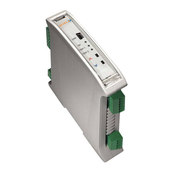
KOS1720 USER GUIDE
To avoid the risk of electric shock and fire, read this instruction document completely before using it..
Dual channel signal conditioner designed to accept RTD, Thermocouple or Potentiometer sensors and provide isolated, industrial process output signals in mA or
Volts. Each output channel may be linked to either input sensor or to a maths function of both sensor signals. This powerful feature allows the device to operate in a
number of different modes.
DISEÑOS Y TECNOLOGÍA S.A., Xarol, 6B, P.I. Les Guixeres, 08915 Badalona, ESPAÑA. www.ditel.es
+34 933 394 758.
IMPORTANT SAFETY REQUIREMENTS.
Max working voltage Terminals (101 to 104) and (201 to 204) Inputs
Max working voltage Terminals (105 to 108) and (205 to 208) Outputs
Max working voltage Terminals (S1 to S2) supply
Isolation supply to Input/output
Any input to any Output
Output to Output, Input to Input
•
This equipment is suitable for environment Installation category II pollution degree 1 and is classed as "PERMANENTLY CONNECTED
EQUIPMENT". The equipment is intended for industrial and commercial application only and not suitable for domestic or medical use.
•
The equipment must be mounted inside an enclosure that provides protection >= IP65. In NORMAL USE, the equipment will only be accessed
for maintenance by qualified personnel. Please ensure the equipment is mounted vertically with terminals (101 to 204) at the bottom. This
will provide maximum ventilation and correct cold junction compensation. This equipment may generate heat, ensure the enclosure size is
adequate to dissipate heat. Be sure to consider any other equipment inside the enclosure.
•
The equipment surfaces may be cleaned with a damp cloth. Use a mild detergent/water on a damp cloth. Ensure the supply is off before
cleaning and on completion of cleaning the equipment is completely dry before the supply is turned back ON.
•
The equipment contains no serviceable parts, or internal adjustments. No attempt must be made to repair the product. Faulty equipment
must be returned to the supplier for repair.
•
This equipment must be installed by a qualified person. All electrical wiring must be carried out in accordance with the appropriate
regulations for the place of installation.
•
DC supply must be derived from a local supply and not a distribution system.
•
To maintain CE EMC requirements, voltage input, DC supply and voltage output wires must be less than 30 metres.
•
Supply (20 to 240) Vac 50/60 Hz (20 to 240) Vdc. If supply is a HAZARDOUS VOLTAGE a supply isolation switch must be installed close to
the equipment with the "OFF" position clearly marked. Also, the supply must be fused with a suitable 1 A (T) fuse (circuit breaker) installed
close the equipment.
•
Receipt and unpacking. Please inspect packaging and instrument thoroughly for any signs of transit damage. If damage is present, do not
use the equipment as safety protection may be affected. Please return damaged equipment to supplier.
•
USB configuration can be performed without the supply being connected. For safety reasons, use 24 Vdc for functional test of unit prior to
fixed installation. The following operations should only be carried out on a disconnected device and under ESD safe conditions: General
mounting, connection and disconnection of wires.
Specification, please refer to supplier's web site latest product data sheet for full specification.
Basic specification
Supply
Input (SELV)
Output (SELV)
Ambient
Configuration (Read the IMPORTANT SAFETY REQUIREMENTS) During configuration the equipment takes its power from the USB port, therefore
no power supply connection is required. The equipment can be configured whilst powered but the computer used must be isolated from the supply earth to
avoid grounded earth loop effects. To avoid electric shock only use a 24 Vdc supply during bench configuration.
USBSpeedLink software
www.status.co.uk
Default settings inputs PT100, outputs (4 to 20) mA, process ranges (0 to 100) °C, fail high, Tag Channel 1 Channel 2.
MT-KOS1720_EN_20181217
User instruction guide
(20 to 240) Vac 50/60 Hz or (20 to 240) Vdc, 3 W, max isolation 4.2 KV supply to input output
3.75 KV to all other ports
RTD, Thermocouple, Potentiometer.
Current (0 to 20) mA, Voltage (0 to 10) V
(-20 to 70) °C Approvals EN61010_1, EN61326
COMPUTER
USB CABLE
±24 Vdc @ 10 mA
±30 Vdc @ 50 mA
240 Vac, ± 240 Vdc
4200 V
3750 V
3750 V
Device
30727725
Advertisement

Subscribe to Our Youtube Channel
Related Manuals for Ditel KOS1720


Summary of Contents for Ditel KOS1720
- Page 1 Volts. Each output channel may be linked to either input sensor or to a maths function of both sensor signals. This powerful feature allows the device to operate in a number of different modes. DISEÑOS Y TECNOLOGÍA S.A., Xarol, 6B, P.I. Les Guixeres, 08915 Badalona, ESPAÑA. www.ditel.es +34 933 394 758.
- Page 2 Installation (Read the IMPORTANT SAFETY REQUIREMENTS) isolation switch Ambient Range + 70 °C Max - 20 °C Min Ø 3mm The equipment must be mounted on a DIN rail style DIN EN 50022 inside a plastic or metal enclosure with a protection level >= IP65. All wiring must be secured. Max cable sizes 2.5 mm.
Need help?
Do you have a question about the KOS1720 and is the answer not in the manual?
Questions and answers