
Related Manuals for IWAKI AMERICA WCT900


Summary of Contents for IWAKI AMERICA WCT900
- Page 1 W900 Series Water Treatment Controller Instruction Manual Five Boynton Road Hopping Brook Park Holliston, MA 01746 USA TEL: 508-429-1110 WEB: www.walchem.com...
- Page 2 Notice © 2021 WALCHEM, Iwaki America Incorporated (hereinafter “Walchem”) 5 Boynton Road, Holliston, MA 01746 USA (508) 429-1110 All Rights Reserved Printed in USA Proprietary Material The information and descriptions contained herein are the property of WALCHEM. Such information and descriptions may not be copied or reproduced by any means, or disseminated or distributed without the express prior written per- mission of WALCHEM, 5 Boynton Road, Holliston, MA 01746.
-
Page 3: Table Of Contents
Contents 1.0 INTRODUCTION ..................1 2.0 SPECIFICATIONS ................... 2 2.1 Measurement Performance ..................2 2.2 Electrical: Input/Output ....................4 2.3 Mechanical ........................ 6 2.4 Variables and their Limits ................... 7 3.0 UNPACKING & INSTALLATION ............11 3.1 Unpacking the unit ....................11 3.2 Mounting the electronic enclosure ................ - Page 4 5.3 Outputs Menu ......................65 5.3.1 Relay, Any Control Mode ..................66 5.3.2 Relay, On/Off Control Mode .................66 5.3.3 Relay, Flow Timer Control Mode ................67 5.3.4 Relay, Bleed and Feed Control Mode ..............67 5.3.5 Relay, Bleed then Feed Control Mode ..............68 5.3.6 Relay, Percent Timer Control Mode ..............68 5.3.7 Relay, Biocide Timer Control Mode ..............68 5.3.8...
- Page 5 6.1.1 Using DHCP .....................108 6.1.2 Using a fixed IP Address ..................109 6.2 Connecting Directly to a Computer ..............109 6.3 Navigating the web pages ................... 109 6.4 Graphs Webpage ....................110 6.5 Software Upgrade ....................110 6.6 Notepad Menu .....................111 6.7 Remote Sensor Calibration ...................111 7.0 MAINTENANCE .................
-
Page 6: Introduction
1.0 INTRODUCTION The Walchem W900 Series controllers offer a high level of flexibility in controlling water treatment applications. • There are four slots that accept a variety of Input/Output Modules, which provides unparalleled versatility. Dual sensor input modules are available that are compatible with a variety of sensors (two sensors per module): »... -
Page 7: Specifications
The standard Ethernet feature provides remote access to the controller’s programming via a PC connected directly, via a local area network, or via Walchem’s Fluent account management server. It also allows emailing of datalog files (in CSV format, compatible with spreadsheets like Excel) and alarms, to up to eight email addresses. The Modbus TCP and BACnet remote communications options allow communication with PC-based applications, HMI/SCADA programs, Building Energy Management systems, Distributed Control Systems (DCS), as well as stand-alone HMI devices. - Page 8 Accuracy ± 0.5% of reading Corrosion Range Resolution 0-2 mpy or mm/year 0.001 mpy or mm/year 0-20 mpy or mm/year 0.01 mpy or mm/year 0-200 mpy or mm/year 0.1 mpy or mm/year 0.01 Cell Contacting Conductivity Range 0-300 µS/cm Resolution 0.01 µS/cm, 0.0001 mS/cm, 0.001 mS/m, 0.0001 S/m, 0.01 ppm Accuracy ±...
-
Page 9: Electrical: Input/Output
Temperature °C Range Multiplier Temperature °C Range Multiplier 181.3 43.5 139.9 39.2 124.2 35.7 111.1 32.8 100.0 30.4 90.6 28.5 82.5 26.9 75.5 25.5 64.3 24.4 55.6 23.6 48.9 22.9 Note: Conductivity ranges on page 2 apply at 25°C. At higher temperatures, the range is reduced per the range multiplier chart. - Page 10 Low Speed Counter-Type Digital Electrical: Optically isolated and providing an electrically isolated 12VDC Inputs power with a nominal 2.3mA current when the digital input switch is closed 0-20 Hz, 25 msec minimum width Devices supported: Any device with isolated open drain, open collector, transistor or reed switch Types: Contacting Flowmeter, Flow Verify High Speed Counter-Type Digital...
-
Page 11: Mechanical
IEC 61326-1:2012 EN 61326-1:2013 Note: For EN61000-4-6, EN61000-4-3 the controller met performance criteria B. *Class A equipment: Equipment suitable for use in establishments other than domestic, and those directly connected to a low voltage (100-240 VAC) power supply network which supplies buildings used for domestic purposes. Mechanical Enclosure Material Polycarbonate... -
Page 12: Variables And Their Limits
Pressure (PSI) vs. Temperature (F) 24.1 20.7 17.2 pH/ORP 13.8 10.3 Cond/Corrosion HP Cond/Steel HP pH/ORP/Steel HP pH/ORP/Steel °F °C Variables and their Limits Sensor Input Settings Low Limit High Limit Alarm limits Low end of sensor range High end of sensor range Input alarm dead band Low end of sensor range High end of sensor range... - Page 13 Value at Min Disturbance (Disturbance Virtual Input only) Value at Max Disturbance (Disturbance Virtual Input only) Stabilization Time (Corrosion only) 0 hours 999 hours Electrode Alarm (Corrosion only) 0 days 365 days Alloy Multiplier (Corrosion only) Tank Capacity 1,000,000 Empty At 0 mA 21 mA Full At...
- Page 14 Min Relay Cycle 0 seconds 300 seconds Set Point Low end of sensor range High end of sensor range Spike Set Point (Spike mode) Low end of sensor range High end of sensor range Onset Time (Spike mode) 0 seconds 23:59:59 HH:MM:SS Duty Cycle Period (On/Off, Spike, Dual Setpoint modes) 0:00 minutes...
- Page 15 Bleed Volume (Flow Meter Ratio mode) 1,000,000 Pump Capacity (Flow Prop mode) 0 gal/hour or l/hour 10,000 gal/hour or l/hour Pump Setting (Flow Prop mode) 100% Specific Gravity (Flow Prop mode) 0 g/ml 9.999 g/ml Target (Flow Prop mode) 0 ppm 1,000,000 ppm Analog (4-20 mA) Output Settings Low Limit...
-
Page 16: Unpacking & Installation
3.0 UNPACKING & INSTALLATION Unpacking the unit Inspect the contents of the carton. Please notify the carrier immediately if there are any signs of damage to the controller or its parts. Contact your distributor if any of the parts are missing. The carton should contain a W900 series controller and an instruction manual. - Page 17 electrical noise. Always route low voltage (sensor) signals with at least a 6” (15 cm) separation from AC voltage wiring. These sensors are affected by the geometry and conductivity of their surroundings, so either maintain 6 inches (15 cm) of sample around the sensor or ensure that any nearby conductive or non-conductive items are consistently positioned.
- Page 18 surfaces will always stay completely wet. The sensor should ideally be installed in the side branch of a 1” or ¾” tee, with the flow entering the tee through the top branch and flowing away from the base of the sensor, towards the tips of the electrodes.
-
Page 19: Icon Definitions
smallest flow control valve is 3250 lbs./hr. 3250 x 0.25 = 812.5 which is too high for continuous sampling. Using an orifice, the flow rate through the smallest diameter plate is 1275 lbs./hr. This is too high for continu- ous sampling. Determine the Orifice or Flow Control Valve Size for this Blowdown Rate Use the following graphs to select a flow control device: Flow Control Valve... -
Page 20: Electrical Installation
Electrical installation The various standard wiring options are shown in figure 1, below. Your controller will arrive from the factory pre- wired or ready for hardwiring. Depending on your configuration of controller options, you may be required to hard- wire some or all of the input/output devices. Refer to figures 6 through 18 for circuit board layout and wiring. Note: when wiring the optional flow meter contactor input, the 4-20 mA outputs or a remote flow switch, it is advis- able to use stranded, twisted, shielded pair wire between 22-26 AWG. - Page 21 Figure 1 Conduit Wiring Ethernet Digital Inputs Sensors Analog Inputs Power switch Analog Outputs Power IN Sensors Analog inputs Relays or Analog Outputs COOLING TOWER METERING PUMPS HEAT EXCHANGER Figure 2 Typical Installation – Cooling Tower...
- Page 22 AC POWER FLOW IN FLOW OUT SUBMERSION ELECTRODE BASE ACID PROBE Figure 3 Typical Installation – Submersion...
- Page 23 RECOMMENDED INSTALLATION Skimmer Blowdown Line INTERMITTENT SAMPLING 3/4" Min. up to Electrode 10 ft. max. with minimal valves, elbows & unions CONDUCTIVITY ELECTRODE Flow Motorized Full Port Block Control Ball Valve Valve or or Solenoid ¾" TEE Orifice Union Valve 2 ft.
- Page 24 SAMPLE RETURN 1 ATMOSPHERE MAXIMUM ROTAMETER 30-100 LPH SENSOR FLOW CELL ISOLATION FLOW VALVE SWITCH (NORMALLY FLOW OPEN) CONTROL VALVE SAMPLE VALVE RECIRCULATION PUMP PROCESS WATER Figure 5 Typical Installation – Disinfection Sensor...
- Page 25 Figure 6 Parts Identification...
- Page 26 I/O Boards 1 through 4 I/O Board P/N Identification Labels I/O Board wiring labels I/O Board Part Number I/O Board 1-4 Terminal Blocks P/N 191910 SENSOR INPUT(2) TBxA - SENSOR 1 TBxB - SENSOR 2 Channel 1 Contacting Conductivity (CCOND) Contacting Conductivity (CCOND) ECOND CCOND...
- Page 27 I/O Boards 1 through 4 I/O Board P/N Identification Labels I/O Board wiring labels I/O Board 1-4 Terminal Blocks I/O Board Part Number P/N 191910 SENSOR INPUT(2) TBxA - SENSOR 1 TBxB - SENSOR 2 ECOND CCOND pH/ORP DIS RCV+ RCV–...
- Page 28 I/O Boards 1 through 4 I/O Board P/N Identification Labels I/O Board wiring labels I/O Board 1-4 Terminal Blocks I/O Board Part Number P/N 191910 SENSOR INPUT(2) TBxA - SENSOR 1 TBxB - SENSOR 2 ECOND CCOND pH/ORP DIS RCV+ RCV–...
- Page 29 I/O Boards 1 through 4 I/O Board P/N Identification Labels I/O Board wiring labels I/O Board Part Number I/O Board 1-4 P/N 191912 4-20 mA INPUT (2) Terminal Blocks TBxA - INPUTS 1-2 TBxB - NOT USED UNPOWERED 2 Wire 2 Wire 3 Wire 4 Wire...
- Page 30 I/O Boards 1 through 4 I/O Board P/N Identification Labels I/O Board wiring labels I/O Board 1-4 Terminal Blocks I/O Board Part Number P/N 191913 4-20 mA INPUT (4) TBxA - INPUTS 1-3 TBxB - INPUT 4 2 Wire 2 Wire UNPOWERED 3 Wire 4 Wire...
- Page 31 I/O Board P/N I/O Boards 1 through 4 Identification Labels I/O Board wiring labels I/O Board 1-4 I/O Board Part Number Terminal Blocks P/N 191914 4-20 mA INPUT (6) TBxA - INPUTS 1-3 TBxB - INPUTS 4-6 UNPOWERED 2 Wire 2 Wire 3 Wire 4 Wire...
- Page 32 I/O Boards 1 through 4 I/O Board P/N Identification Labels I/O Board wiring labels I/O Board 1-4 Terminal Blocks I/O Board Part Number P/N 191915 4-20 mA OUTPUT (2) TBxA - OUTPUTS 1-2 TBxB - NOT USED 4-20 mA Output –...
- Page 33 I/O Boards 1 through 4 I/O Board P/N Identification Labels I/O Board wiring labels I/O Board 1-4 I/O Board Part Number Terminal Blocks P/N 191916 4-20 mA OUTPUT (4) TBxA - OUTPUTS 1-2 TBxB - OUTPUTS 3-4 4-20 mA Output –...
- Page 34 I/O Boards 1 through 4 I/O Board P/N Identification Labels I/O Board wiring labels I/O Board Part Number I/O Board 1-4 Terminal Blocks P/N 191918 4-20 mA INPUT (2)/OUTPUT (4) TBxA - INPUT 1, OUTPUTS 1-2 TBxB - INPUT 2, OUTPUTS 3-4 2 Wire 2 Wire 4-20 mA...
- Page 35 I/O Board P/N I/O Boards 1 through 4 Identification Labels I/O Board wiring labels I/O Board 1-4 Terminal Blocks I/O Board Part Number P/N 191920 CORROSION INPUT(2) TBxA - SENSOR 1 TBxB - SENSOR 2 Channel 1 CORROSION XMT RED XMT (Red) RCV GRN RCV (Green)
- Page 36 D1– SIGNAL IN – D2– POWER +12V D3– FLOW SWITCH D4– Hall Effect Contact Closure: FLOW METER Polarity not critical Reed Switch D5– FLOW METER Polarity not Critical D6– D7– D8– D9– D10+ D10– D11+ D11– D12+ D12– TBDI Figure 17 Digital Input Wiring...
- Page 37 Relay Model Code Powered Powered Powered Powered Powered Powered Powered Powered Powered Powered Powered Powered Powered Powered Powered Pulse Pulse Powered Powered Powered Powered Pulse Pulse Pulse Pulse Powered Powered Pulse Pulse Powered Powered Pulse Pulse Powered Powered Powered Powered Powered Powered Pulse...
-
Page 38: Function Overview
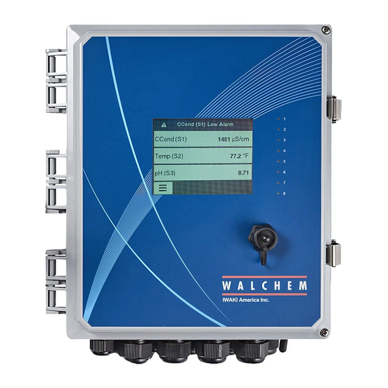
4.0 FUNCTION OVERVIEW Front Panel Figure 19 Front Panel Touchscreen A Home screen is displayed while the controller is on. This display shows a user-defined list of input readings or status of outputs. Touching any of the items on the Home Screen will bring up the item’s Details Screen, where you can access calibration and setting menus. - Page 39 Outputs Menu Configuration Menu HOA Menu Graph Menu Home Page Other icons may appear in the menu screens. Calibration icon appears in sensor input menus and brings up the calibration menu Cancel icon aborts a calibration or setting change The Page Down icon scrolls down to a new page in a list of options. The Page Up icon scrolls up to a new page in a list of options.
-
Page 40: Startup
Overview of the use of icons Changing Numeric Values To change a number, use the Character Delete icon to the digit to be changed. If the new number will be neg- ative, start with touching the minus sign, then use the numeric touchpad and decimal point to type the number (some entries must be integers and the decimal will be ignored and the setting rounded to the nearest integer). - Page 41 Set global units of measure Touch the Scroll Up or Down icon until Global Units is displayed and then touch it. Touch the desired units. Touch the Confirm icon to accept the change. Set temperature units of measure Touch the Scroll Up or Down icon until Temp Units is displayed and then touch it. Touch the desired units. Touch the Confirm icon to accept the change.
- Page 42 Inputs MAIN MENU/HOME SCREEN OVERVIEW Sensor (S11) 3038 µS/cm Temp (S12) 77.1°F Generic AI (S21) 30.5% Generic AI (S22) 37.9% List of possible Inputs: Contacting Conductivity Electrodeless Conductivity HOME SCREEN (example) Temperature Flowswitch (D1) No Flow Disinfection SENSOR (S1) Config Generic CCond (S11) 3041 µS/cm...
- Page 43 Inputs Main Menu 09:19:01 14-Mar-2017 Config Sensor (S11) 3038 µS/cm Inputs Temp (S12) 77.1°F Outputs Generic AI (S21) 30.5% Alarms Graph Generic AI (S22) 37.9% > Calibration Inputs>Sensor (S11) SENSOR (S1) One Point Process Calibration Details Screen One Point Buffer Calibration Content varies with Two Point Buffer Calibration sensor type...
- Page 44 INPUTS SENSOR (S1) Additional Settings for DI State: DI State (D1-D12) Calculation (V1-V8) Additional Settings for Calculation: Alarm & Datalog Suppression Input 2 Low Range Open Message Alarms Total Time Constant 2 High Range Closed Message Deadband Reset Time Total Calculation Mode Smoothing Factor Interlock...
- Page 45 RELAY OUTPUTS (R1-R8) and VIRTUAL OUTPUTS (C1-C8) Outputs Main Menu 09:19:01 14-Mar-2017 (CONTINUED ON NEXT PAGE) On/Off (R1) Config Inputs Inhibitor (R2) Outputs Only if HVAC mode is enabled Additional Settings for Intermittent Sampling Mode: Flow Timer (R3) Int. Sampling (R1-R8) Sample Time Min Relay Cycle Alarms...
- Page 46 Outputs Main Menu 09:19:01 14-Mar-2017 On/Off (R1) Config Inputs Inhibitor (R2) Outputs RELAY OUTPUTS (R1-R8) and VIRTUAL OUTPUTS (C1-C8) Flow Timer (R3) Alarms Graph Continued Manual (R4) Outputs>On/Off (R1) Details Screen Content varies with output type Additional Settings for On/O Dis: On/Off Dis (R1-R8) Duty Cycle Minimum Relay Cycle...
- Page 47 ANALOG OUTPUTS (A11-A44) and VIRTUAL OUTPUTS (C1-C8) Additional settings for Retransmit Mode: Additional Settings for Manual Control Mode: Retransmit (A11-A44) Manual Control (A11-A44) Error Output Hand Time Limit HOA Setting Reset Time Total HOA Setting Reset Time Total Input Name 4 mA Value Interlock Channels Name...
- Page 48 CONFIG MENU HOME SCREEN (example) Config Flowswitch (D1) No Flow Main Menu 09:19:01 14-Mar-2017 Global Settings SENSOR (S1) CCond (S11) 3041 µS/cm Inputs Config Security Settings Ethernet Settings Temp (S12) 77.0°F Outputs Ethernet Details Flowswitch (D1) No Flow Alarms Graph Additional Config Settings: WiFi Settings WiFi Details...
-
Page 49: Shut Down
Outputs (see section 5.3) Program the settings for each output The R1 relay output will be displayed. Touch the relay field to get to the Details screen. Touch the Settings icon. If the name of the relay does not describe the control mode desired, touch the Scroll Down icon until Mode field is displayed. - Page 50 Touch the input to access that input’s details, calibration (if applicable) and settings. Sensor Input Details The details for any type of sensor input include the current value read, alarms, the raw (uncalibrated) signal, the sensor type, and the calibration gain and offset. If the sensor has automatic temperature compensation, then the sensor’s temperature value and alarms, the temperature resistance value read, and the type of temperature element required are also displayed under a separate sensor input menu.
- Page 51 Remove the sensor from the process, rinse it off, and place it in the buffer solution. Touch Confirm when ready. Stabilization When the temperature (if applicable) and signal from the sensor is stable, the controller will automatically move to the next step. If they don’t stabilize you may manually go to the next step by touching Confirm. Second Buffer Temperature (only appears if no temperature sensor is detected for sensor types that use auto- matic temperature compensation) Enter the temperature of the buffer and press Confirm.
- Page 52 Third Buffer Value (does not appear if automatic buffer recognition is used) Enter the value of the buffer being used Rinse Electrode Remove the sensor from the process, rinse it off, and place it in the buffer solution. Touch Confirm when ready. Stabilization When the temperature (if applicable) and signal from the sensor is stable, the controller will automatically move to the next step.
-
Page 53: Contacting Conductivity
5.2.1 Contacting Conductivity Settings Touch the Settings icon to view or change the settings related to the sensor. Alarms Low-Low, Low, High and High-High Alarms limits may be set. Deadband This is the Alarm Deadband. For example, if the High Alarm is 3000, and the deadband is 10, the alarm will activate at 3001 and deactivate at 2990. -
Page 54: Temperature
Installation Factor Do not change unless instructed by the factory. Cable Length The controller automatically compensates for errors in the reading caused by varying the length of the cable. Gauge The cable length compensation depends upon the gauge of wire used to extend the cable Cell Constant Do not change unless instructed by the factory. -
Page 55: Orp
Reset Calibration Values Enter this menu to reset the sensor calibration back to factory defaults. Cal Required Alarm To get an alarm message as a reminder to calibrate the sensor on a regular schedule, enter the number of days between calibrations. Set it to 0 if no reminders are necessary. Buffers Select if calibration buffers will be manually entered, or if they will be automatically detected, and if so, which set of buffers will be used. -
Page 56: Generic Sensor
Alarm & Datalog If any of the relays or digital inputs are selected, any alarms related to this input Suppression will be suppressed if the selected relay or digital input is active. At the same time, all datalogs and graphs containing the input will show no data for the duration of the activation. -
Page 57: Corrosion Input
5.2.8 Corrosion Input ONLY AVAILABLE IF A CORROSION INPUT BOARD IS INSTALLED Input Details The details for this type of input include the current corrosion rate, alarms, status, current stage in the measurement cycle, the elapsed time in the current cycle, the raw (uncalibrated) corrosion rate, the number of days in service of the electrodes, the calibration offset, the date of last calibration, and the type of input. -
Page 58: Corrosion Imbalance Input
Aluminum Brass 1.62 C68700 Copper/Nickel 90/10 1.80 C70610 Copper/Nickel 70/30 1.50 C71500 AISI 4130 Alloy Steel 1.00 G41300 Lead 2.57 L50045 Monel 400 Nickel 1.13 N04400 Monel K500 Nickel 1.04 N05500 Hastelloy C22 0.85 N06022 Inconel 600 Nickel 0.95 N06600 Incoloy Alloy 20 0.98 N08020... -
Page 59: Transmitter Input And Ai Monitor Input
5.2.10 Transmitter Input and AI Monitor Input Select AI monitor if the device connected can be calibrated on its own and the W900 calibration will only be in units of mA. Select Transmitter if the device connected cannot be calibrated on its own and the W900 will be used to calibrate in engineering units of measure. -
Page 60: Analog Flowmeter Input
Dye/Product Ratio Enter the value for the ratio of ppb of dye to ppm of inhibitor that is in the inhibitor product being fed. Name The name used to identify the transmitter may be changed. Type Select the type of sensor to be connected. The choice of Analog Input is only avail- able if that type of sensor card is installed. -
Page 61: Di State
Alarm & Datalog If any of the relays or digital inputs are selected, any alarms related to this input Suppression will be suppressed if the selected relay or digital input is active. At the same time, all datalogs and graphs containing the input will show no data for the duration of the activation. -
Page 62: Flow Meter, Paddlewheel Type
Deadband This is the Alarm Deadband. For example, if the High Alarm is 100, and the deadband is 1, the alarm will activate at 100 and deactivate at 99 Totalizer Alarm Enter the high limit on the total volume of water accumulated above which an alarm will be activated. -
Page 63: Feed Monitor
5.2.17 Feed Monitor The Feed Monitor Digital Input type performs the following functions: • Monitors a pulse signal from a pump (Iwaki PosiFlow, Tacmina Flow Checker, LMI Digital Pulse, etc) • Totalizes the chemical feed and calculates the current flow rate •... -
Page 64: Di Counter Input
Interlocking or Activating any Control Output with a Feed Monitor Input Digital Input channels are available for selection as Interlock Channels or Activate With Channels by any output. If a Feed Monitor is selected in this manner, the Digital Input will trigger that action if any alarm (Flow Verify, Total Alarm, or Range Alarm) is currently active. -
Page 65: Remote Modbus Di State
time of last total reset, alarms, and the current type of input setting. Settings Touch the Settings icon to view or change the settings related to the virtual input. Alarms Low and High Alarm limits may be set. Deadband This is the Alarm Deadband. For example, if the High Alarm is 100, and the deadband is 1, the alarm will activate at 100 and deactivate at 99 Totalizer Alarm A high limit on the total number of contact closures accumulated may be set. -
Page 66: Virtual Input - Calculation
Alarm Choose if an alarm should be generated when the virtual switch is open, or closed, or if no alarm should ever be generated. Modbus Mode Select Server Mode is the Modbus application will write the value to the input on its own schedule. -
Page 67: Virtual Input - Redundant
Constant Only appears if the Input selection is Constant. Enter the value. Input 2 Select the physical input or select Constant, whose value will be used in the calculation shown above as the Input 2 in the formula. Constant 2 Only appears if the Input 2 selection is Constant. -
Page 68: Virtual Input - Raw Value
Deadband This is the Alarm Deadband. For example, if the Deviation Alarm is 1.00, and the deadband is 0.1, the alarm will activate if the sensor readings are 1.01 units apart, and deactivate at 0.89 units apart. Alarm & Datalog If any of the relays or digital inputs are selected, any alarms related to this input Suppression will be suppressed if the selected relay or digital input is active. - Page 69 flow rate, with a Disturbance Type Virtual Input defining the impact of the flow rate on the control output. Based on the disturbance input channel selection, minimum and maximum disturbance input readings, and de- fined multiplier values at the min and max disturbance readings, this Virtual Input generates a value that is used to multiply to a primary control value.
-
Page 70: Remote Modbus Sensor Virtual Input
5.2.24 Remote Modbus Sensor Virtual Input ONLY AVAILABLE IF A MODBUS KEY FILE HAS BEEN IMPORTED AND THE COMM STATUS IN THE REMOTE COMMUNICATIONS MENU HAS BEEN SET TO MODBUS The Remote Modbus sensor virtual input is used to simulate a sensor by obtaining the sensor value from a Modbus application via Modbus TCP. -
Page 71: Relay, Any Control Mode
5.3.1 Relay, Any Control Mode Settings Touch the Settings icon to view or change the settings related to the relay. Settings that are available for any control mode include: HOA Setting Select Hand, Off or Auto mode by touching the desired mode. Output Time Limit Enter the maximum amount of time that the relay can be continuously activated. -
Page 72: Relay, Flow Timer Control Mode
Input Select the sensor to be used by this relay. Direction Select the control direction. Daily Max Time Enter the maximum amount of accumulated on-time, in Hand or Auto modes, that the relay can have between midnight and midnight the next day. If the time is exceeded, the relay will deactivate, and a Daily Max Timeout alarm will be triggered. -
Page 73: Relay, Bleed Then Feed Control Mode
Daily Max Time Enter the maximum amount of accumulated on-time, in Hand or Auto modes, that the relay can have between midnight and midnight the next day. If the time is exceeded, the relay will deactivate, and a Daily Max Timeout alarm will be triggered. The alarm will clear, and relay allowed to reactivate at midnight the next day. - Page 74 This algorithm is typically used to provide a baseline amount of chlorine for disinfection, and periodically shock- ing the system with a larger dose. During normal operation, the relay will be reacting to the sensor to maintain a set point within a programmable Deadband, as described in On/Off Control Mode above. When a Spike event triggers, the algorithm will change from the normal set point to the Spike Set Point, for the programmed time.
-
Page 75: Relay, Alarm Output Mode
Week Only appears if Repetition is longer than 1 Week. Select the week during which the event will occur. Day Only appears if Repetition is longer than Daily. Select the day of the week during which the event will occur. Start Time Enter the time of day to start the event. -
Page 76: Relay, Intermittent Sampling Control Mode
Settings Touch the Settings icon to view or change the settings related to the relay. Set point Enter the sensor process value at which the relay will be off for the entire Sample Period. Proportional Band Enter the distance that the sensor process value is away from the set point at which the relay will be on for the entire Sample Period. -
Page 77: Relay, Manual Mode
Proportional Band (only shown if trap sample is enabled) Enter the conductivity value above the set point at which the maximum blowdown time will occur. For example, if the Set point is 2000 uS/cm, and the Proportional Band is 200 uS/cm, then if the conductivity is above 2200 uS/cm the blowdown valve will open for the Maximum Blowdown time described be- low. -
Page 78: Relay, Pid Control Mode
Direction Set the control direction. 5.3.13 Relay, PID Control Mode ONLY AVAILABLE IF CONTROLLER INCLUDES PULSE OUTPUT HARDWARE & HVAC MODE IS DISABLED The PID algorithm controls a solid state relay using standard Proportional-Integral-Derivative control logic. The algorithm provides feedback control based on an error value continuously calculated as the difference between a measured process variable and a desired set point. - Page 79 de(t) Output (%) = K e(t) + K e(t)dt + K Integral Value Management To determine the integral component of the PID calculation, the controller software must maintain a running total of the accumulated area under the error curve (Current Integral). The sign of the value added to the accumulated Current Integral during each cycle may be positive or negative based on the current Direction setting as well as the relative values of the current process reading and the set point.
-
Page 80: Relay, Dual Set Point Mode
Proportional Gain When the Gain Form setting is Parallel, this unitless value is multiplied by the normalized error (current process value versus set point) to determine the proportional component of the calculated output percent. Integral Time When the Gain Form setting is Standard, this value is divided into the integral of the normalized error (area under the error curve), then multiplied by the Gain to determine the integral component of the calculated output percent. -
Page 81: Relay, Timer Control Mode
Duty Cycle Enter the percentage of the cycle period that the relay will be active. Set the percentage to 100 if use of a duty cycle is not required. On Delay Time Enter the delay time for relay activation in hours:minutes:seconds. Set the time to 00:00:00 to immediately activate the relay. -
Page 82: Relay, Probe Wash Control Mode
Touch the Settings icon to view or change the settings related to the relay. Event 1 (through 10) Enter these menus to program timer events via the menus below: Repetition Select the time cycle to repeat the event: Hourly, Daily, 1 Week, 2 Week, 4 Week, or None. -
Page 83: Relay, Spike Control Mode
Settings Touch the Settings icon to view or change the settings related to the relay. Event 1 (through 10) Enter these menus to program timer events via the menus below: Repetition Select the time cycle to repeat the event: Hourly, Daily, 1 Week, 2 Week, 4 Week, or None. - Page 84 The relay activation duration timer continues counting when the timer relay is forced on, and ends at the expected time (event start time plus duration). If the “activate with” condition continues after the end of the event time, the relay remains activated. Alarms An Event Skipped alarm is set when a second timer event occurs while one event is still running.
-
Page 85: Relay Output, Flow Proportional Mode
Daily Max Time Enter the maximum amount of accumulated on-time, in Hand or Auto modes, that the relay can have between midnight and midnight the next day. If the time is exceeded, the relay will deactivate, and a Daily Max Timeout alarm will be triggered. -
Page 86: Relay, Target Ppm Control Mode
5.3.19 Relay, Target PPM Control Mode ONLY AVAILABLE IF HVAC MODE IS ENABLED Overview In Target PPM control mode, the controller monitors the total volume of flow through up to two analog or digital flow meters, and after a programmable volume has been accumulated, the relay activates for a calculated time to achieve a target PPM level. -
Page 87: Relay, Ppm By Volume Control Mode
Daily Max Time Enter the maximum amount of accumulated on-time, in Hand or Auto modes, that the relay can have between midnight and midnight the next day. If the time is exceeded, the relay will deactivate, and a Daily Max Timeout alarm will be triggered. The alarm will clear, and relay allowed to reactivate at midnight the next day. -
Page 88: Relay, Flow Proportional Mode
Cycles Input Select the virtual input that is programmed as a Ratio calculation of the system conductivity/makeup conductivity, or select None. Low Cycles Limit Enter the lower limit for cycles of concentration, if used. The calculated on-time is limited to a maximum value if the cycles of concentration gets too low. Daily Max Time Enter the maximum amount of accumulated on-time, in Hand or Auto modes, that the relay can have between midnight and midnight the next day. -
Page 89: Relay, Counter Timer Control Mode
Cycles Input Select the virtual input that is programmed as a Ratio calculation of the system conductivity/makeup conductivity, or select None. Low Cycles Limit Enter the lower limit for cycles of concentration, if used. The calculated on-time is limited to a maximum value if the cycles of concentration gets too low. 5.3.22 Relay, Counter Timer Control Mode ONLY AVAILABLE IF HVAC MODES ARE DISABLED IN CONFIG MENU –... -
Page 90: Relay Output, Volumetric Blending Control Mode
Duty Cycle Period Using a duty cycle helps to prevent overshooting the set point in applications where the response of the sensor to chemical additions is slow. Specify the amount of time for the cycle, and the percentage of that cycle time that the relay will be active. The relay will be off for the rest of the cycle, even if the set point has not been satisfied. -
Page 91: Relay, Dual Switch Control Mode
Daily Max Time Enter the maximum amount of accumulated on-time, in Hand or Auto modes, that the relay can have between midnight and midnight the next day. If the time is exceeded, the relay will deactivate, and a Daily Max Timeout alarm will be triggered. The alarm will clear, and relay allowed to reactivate at midnight the next day. -
Page 92: Relay Or Analog Output, Lag Control Mode
Output Details The details for this type of output include the relay on/off state, HOA mode Interlock or delay status, current cycle on time, time on over the past 24 hours, the total accumulated on-time since the last reset, alarms related to this output, relay type, and the current control mode setting. - Page 93 tionality. The last Lag mode relay in the chain (R3) offers various settings that are used to define the desired control operations for the entire Lead Lag group. Selectable Lead Lag control options include backup, wear leveling, and/ or activating additional outputs based on various criteria. Backup Pump Control By default, Lead Lag groups always provide backup operation if the Lead control mode determines that its output should be energized but it is disabled due to a Flow Verify alarm and/or because the Lead output HOA setting is...
- Page 94 Wear Leveling Modes After the Lead Lag group is defined, additional parameters can be configured within the settings list of the last out- put in the group. These options optimize the behavior of the Lead Lag functionality. Several different wear leveling options can be selected to control the order in which outputs are activated.
- Page 95 Disabled No action is taken to activate more than one output within the Lead Lag group of outputs. This mode is used when a group of Lead Lag outputs exists only to provide backup in case of a Flow Verify failure on one of the pumps, or if a pump is taken out of service, and/or if only wear leveling is desired.
- Page 96 Example 1: A lift station includes a tank with a high level switch (D1) and a high-high level switch (D2). Three pumps are configured as a Lead Lag group (R1←R2←R3). The Lead output (R1) is set for Manual control mode with an Activate With Channels selection of D1 (high level switch), R1 will be energized if D1 closes.
- Page 97 currently energized within the group, the elapsed time since the last change in the number of outputs energized, the elapsed time since the last wear leveling evaluation, the type of output, and the current control mode setting. Settings Touch the Settings icon to view or change the settings related to the relay. The Lag control mode output defined as the Last Lag within the Lead Lag group offers settings to define the param- eters controlling operation of the entire group.
-
Page 98: Relay Output, Flow Meter Ratio Control Mode
Several standard settings that are available for most control modes are not available for Lag outputs. These features affect the entire Lead Lag group and can be specified only within the Lead output’s settings. The settings for these fields are propagated down through the entire Lead Lag group when changed for the Lead output. Although the settings for these fields are identical for all outputs in the Lead Lag group, the handling by each Lag output may be independent or group-managed. -
Page 99: Relay Or Analog Output, Disturbance Variable Control Mode
through one or two water meters, and after a programmable amount, activates the relay to control a programmable volume out through one or two bleed water meters. Output Details The details for this type of output include the relay on/off state, HOA mode or Interlock status, Accumulated make- up water total, bleed cycle volume, remaining volume, relay on-time for this cycle, accumulated on-time, alarms related to this output, relay type, and the current control mode setting. -
Page 100: Analog Output, Proportional Control Mode
be selected as a relay output that activates if the flow rate is either too high or too low. These conditions would trigger a switch from pH control to flow based control. Output Details The details for this type of output include the % output, HOA mode or Interlock status, alarms related to this output, Primary Output %, Disturbance Input value, current cycle on-time, accumulated on-time, raw output (in mA or pulses/min.), relay type, and the current control mode setting. -
Page 101: Analog Output, Flow Proportional Mode
Off Mode Output Enter the output mA value desired when the output is in Off mode, or being Interlocked, or during a calibration of the sensor being used as an input. The acceptable range is 0 to 21 mA. Error Output Enter the output mA desired when the sensor is not giving the controller a valid signal. -
Page 102: Analog Output, Pid Control Mode
5.3.32 Analog Output, PID Control Mode ONLY AVAILABLE IF CONTROLLER INCLUDES ANALOG OUTPUT HARDWARE & HVAC MODE IS DISABLED The PID algorithm controls an analog (4-20 mA) output using standard Proportional-Integral-Derivative control logic. The algorithm provides feedback control based on an error value continuously calculated as the difference between a measured process variable and a desired set point. - Page 103 de(t) Output (%) = K e(t) + K e(t)dt + K Integral Value Management To determine the integral component of the PID calculation, the controller software must maintain a running total of the accumulated area under the error curve (Current Integral). The sign of the value added to the accumulated Current Integral during each cycle may be positive or negative based on the current Direction setting as well as the relative values of the current process reading and the set point.
-
Page 104: Analog Output, Manual Mode
Integral Gain When the Gain Form setting is Parallel, this value is multiplied by the integral of the normalized error (area under the error curve) to determine the integral component of the calculated output percent. Derivative Time When the Gain Form setting is Standard, this value is multiplied by the change in error between the current reading and the previous reading, then multiplied by the Gain to determine the derivative component of the calculated output percent. -
Page 105: Configuration Menu
4 mA Value Enter the process value to correspond to a 4 mA output signal. 20 mA Value Enter the process value to correspond to a 20 mA output signal. Hand Output Enter the output % desired when the output is in Hand mode. Error Output Enter the output % desired when the input signal is invalid (Error mode). -
Page 106: Ethernet Details
Fluent Alarm Delay Enter the number of minutes to delay in sending out a Fluent Comms Error message if a data packet is not successfully sent. In order to delay at all, the time must exceed the Update Period time. TCP Timeout Do not change from the default of 1 second unless directed to by techical service. -
Page 107: Wifi Details
Gateway Connection Infrastructure Mode. Only appears if a Dual WiFi/Ethernet type WiFi card is installed. Select which connection, Ethernet or WiFi, will provide the Gateway function. This means that all external Internet connections such as Fluent or emails will default to using this connection. -
Page 108: Remote Communications (Modbus And Bacnet)
WiFi Status Displays if the WiFi is enabled or disabled. Signal Strength Displays the signal strength in the range of -100 to -30 dBm RSSI Displays the Relative Signal Strength In percent (0% = -100 dBm and 100% is greater than -49 dBm). -
Page 109: Email Report Settings
Verbose Logging If logging is Enabled, all Modbus or BACnet requests will be logged in the Event Log (any errors, the function called, starting register, number of registers, value of the first register, get object requests). This is useful when first setting up the HMI, but it will quickly fill the Event Log if it is not Disabled during normal operation. -
Page 110: Display Settings
SMTP Server Will not appear if Email Server is Walchem Fluent. Enter the SMTP server address, either numeric or its name. SMTP Port Will not appear if Email Server is Walchem Fluent. Walchem Fluent email requires that port 49887 is open. Enter the port to be used by email server. The default is port 25 for SMTP, port 587 for ASMTP, and port 465 for TLS/SSL. -
Page 111: Controller Details
Log Frequency Select the amount of time between data points. The amount of time allowed varies with the Data Log Range. If the Data Log Range is selected as Since Previous download, the choices for frequency of data points will be limited by how far back in time the last download occurred. -
Page 112: Hoa Menu
Sensor Board #1 - #4 Displays the part number and revision of the I/O boards (One entry for each board installed, up to 4) Software Version Displays the software version on each I/O board (One entry for each board installed, up to 4) Last Data Log Displays the date and time of the last data log download... -
Page 113: Operation Using Ethernet
Touching the or the icons will redraw the graph forward or backwards in time, in increments of one time range. It can only go back in time to the point where the data log file used to generate the graph starts. Changing the time frame while in the graph view, after moving back in time, shows data from that past time. -
Page 114: Using A Fixed Ip Address
After a power cycle of the controller, return to Config, then Ethernet Details to view the Controller IP Address that has been assigned to the controller by the network. 6.1.2 Using a fixed IP Address Using the touchscreen, from the Main menu, touch Config, then touch Ethernet Settings, then touch DHCP Setting. Touch Disabled, then the Confirm icon. -
Page 115: Graphs Webpage
site, that are useful if the controller is connected to the Internet. Graphs Webpage The graphs page can display up to 8 parameters at a time. All possible parameters available based upon the controller programming are listed in one column. Click the right arrow to add the highlighted parameter to the Selected column, or the left arrow to move a selected parameter back out. -
Page 116: Notepad Menu
Then if successful: Complete Or not successful: Failed Upgrade in progress (showing each individual step in the upgrade installation) When the upgrade installation is complete, the login webpage will appear. Status or error messages will be recorded in the System Log. Notepad Menu The Notepad Menu is used to store up to 10,240 bytes of notes (approximately one byte per character for English language). -
Page 117: Replacing The Fuse Protecting Powered Relays
If the variance in readings is greater than 5%, increase the frequency of electrode cleaning. If there is less than 5% change in the reading, the electrode was not dirty and can be cleaned less often. Cleaning Procedure The electrode can normally be cleaned using a cloth or paper towel and a mild detergent. If coated with scale, clean with a dilute (5%) solution of hydrochloric acid solution. -
Page 118: Electrodeless Conductivity Sensors
Wrong cell constant entered Program the controller cell constant setting at the value that matches the electrode being used Incorrect temperature reading or setting Ensure that the temperature is accurate Incorrect cable length or wire gauge setting Set to the correct values Faulty electrode Replace electrode 8.1.2... -
Page 119: Analog Inputs
Air bubbles in electrolyte Refill membrane cap with electrolyte. Dirty membrane Clean membrane Loose membrane cap Tighten membrane cap. Faulty membrane Replace membrane cap. High Pressure Reduce pressure to below 1 atmosphere and refill cap with electrolyte No electrolyte fill solution in membrane cap Fill membrane cap with electrolyte. - Page 120 Wrong chemical is being controlled. Replace with correct chemical. The sensor is not responding to changes. Repair or replace sensor. Evaluate mixing or recirculation. The pump is siphoning, valve leaking. Repair or replace the control device or re-route tubing. Control output has been left in “HAND” mode. Switch back to “AUTO”.
- Page 121 Faulty feed monitoring sensor Replace feed monitoring sensor Blown fuse Verify the pump is getting power. Replace fuse Faulty output relay Replace relay board Faulty digital input Verify that feed monitoring device is making contact closures using an ohmmeter. If OK, and connected properly, replace the controller circuit board.
- Page 122 SYSTEM TEMP LOW This alarm indicates that the temperature inside the controller is below -10 °C. Possible Cause Correction Action Low ambient temperatures Provide heat for the controller SYSTEM TEMP HIGH This alarm indicates that the temperature of the controller or sensor processor IC is above 75 °C, or that the temperature of the Ethernet card processor IC is above 85 °C.
- Page 123 Wrong digital input assigned to the output Correct programming error Faulty verification device Repair or replace device Faulty wiring of output to pump Correct wiring Faulty output board Repair or replace board Faulty digital input Replace board CONTROLLER, POWER, DISPLAY, OR SENSOR BOARD ERROR This alarm occurs if the board listed is not recognized Possible Cause Correction Action...
-
Page 124: Procedure For Evaluation Of Conductivity Electrode
FRAM FILE SYSTEM ERROR This alarm occurs if the FRAM is not detected at power up Possible Cause Correction Action The FRAM was or is not functioning If the error message clears on its own, no action is required. If the error message persists, cycle power. If the error message still persists, replace the controller board. -
Page 125: Procedure For Evaluation Of The Ph/Orp Electrode
Try cleaning the electrode first (refer to Sect. 7.1). To check the electrode, check the electrode connections to the terminal strip (refer to Figure 7). Make sure that the correct colors go to the correct terminals, and that the connections are tight. - Page 126 Faulty power supply Replace power supply I/O BOARD LEDs Indicates the status of the sensor board. Blinks slowly for several seconds during power-up. Normal operation is OFF. If not behaving this way: Possible Cause Corrective Action Sensor card locked up Try a power cycle to reset it Sensor card not seated correctly Unplug the card and plug it back in...
-
Page 127: Spare Parts Identification
9.0 Spare Parts Identification 192612, W900 WiFi PCBA, WiFi Only, Ethernet Disabled, 20 Pin 191944, W900 WiFi PCBA, WiFi + Ethernet, 20 Pin 191945, W900 WiFi PCBA, WiFi Only, Ethernet Disabled, 10 Pin (s/n 180812xxxx or earlier) 191946, W900 WiFi PCBA, WiFi + Ethernet, 10 Pin (s/n 180812xxxx or earlier) 191930 I/O Board Holder 191931 Safety Cover... - Page 128 WCT900 Sensor Options PAFMNN, PBFMNN, PAHMNN, PBHMNN, PAIMNN, PBIMNN PAFMNN: Graphite contacting conductivity + Flow Switch manifold on panel + WEL-PHF no ATC + LD2 PAHMNN: PAIMNN: + WEL-MVR + LD2 + WEL-MVF + LD2 PBFMNN: 316SS contacting conductivity + Flow Switch manifold on panel + WEL-PHF no ATC + LD2...
- Page 129 WCT900 Sensor Options PAEFMN, PBEFMN, PAEHMN, PBEHMN, PAEIMN, PBEIMN PAEFMN: Graphite contacting conductivity + Flow Switch manifold on panel + Makeup Conductivity + WEL-PHF no ATC + LD2 PAEHMN: + WEL-MVR + LD2 PAEIMN: + WEL-MVF + LD2 PBEFMN: 316SS contacting conductivity + Flow Switch manifold on panel...
- Page 130 WCT900 Sensor Options PAFNNN, PBFNNN, PAHNNN, PBHNNN, PAINNN, PBINNN PAFNNN: Graphite contacting conductivity + Flow Switch manifold on panel + WEL-PHF no ATC PAHNNN: PAINNN: + WEL-MVR + WEL-MVF PBFNNN: 316SS contacting conductivity + Flow Switch manifold on panel + WEL-PHF no ATC...
- Page 131 WCT900 Sensor Options PAEFNN, PBEFNN, PAEHNN, PBEHNN, PAEINN, PBEINN PAEFNN: Graphite contacting conductivity + Flow Switch manifold on panel + Makeup Conductivity+ WEL-PHF no ATC PAEHNN: PAEINN: + WEL-MVF + WEL-MVR PBEFNN: 316SS contacting conductivity + Flow Switch manifold on panel...
- Page 132 WCT900 Sensor Options PAMNNN, PBMNNN PAMNNN: Graphite contacting conductivity + Flow Switch manifold on panel + LD2 PBMNNN: 316SS contacting conductivity + Flow Switch manifold on panel + LD2...
- Page 133 WCT900 Sensor Options PAEMNN, PBEMNN PAEMNN: Graphite contacting conductivity + Flow Switch manifold on panel+ makeup sensor + LD2 PBMNNN: 316SS contacting conductivity + Flow Switch manifold on panel + makeup sensor + LD2...
- Page 134 WCT900 Sensor Options PANNNN, PBNNNN PANNNN: Graphite contacting conductivity + Flow Switch manifold on panel PBNNNN: 316SS contacting conductivity + Flow Switch manifold on panel...
- Page 135 WCT900 Sensor Options PAENNN, PBENNN PAENNN: Graphite contacting conductivity + Flow Switch manifold on panel + makeup sensor PBENNN: 316SS contacting conductivity + Flow Switch manifold on panel + makeup sensor...
- Page 136 WCT900 Sensor Options PAPNNN, PBPNNN PAPNNN: Graphite contacting conductivity + Flow Switch manifold on panel + Pyxis PBPNNN: 316SS contacting conductivity + Flow Switch manifold on panel + Pyxis...
- Page 137 WCT900 Sensor Options PAEPNN, PBEPNN PAEPNN: Graphite contacting conductivity + Flow Switch manifold on panel + Pyxis + makeup sensor PBEPNN: 316SS contacting conductivity + Flow Switch manifold on panel + Pyxis + makeup sensor...
- Page 138 WCT900 Sensor Options PAFHMR, PBFHMR, PAFIMR, PBFIMR PAFHMR: Graphite contacting conductivity + Flow Switch manifold on panel + WEL-PHF no ATC + Little Dipper 2 +Dual Corrosion + WEL-MVR PAFIMR: + WEL-MVF PBFHMR: 316SS contacting conductivity + Flow Switch manifold on panel+ WEL-PHF...
- Page 139 WCT900 Sensor Options PFNNNN, PHNNNN, PINNNN and WIN900 Sensor Option PBNNNN W900-CT-PFNNNN: Flow Switch manifold on panel + WEL-PHF no ATC PHNNNN: + WEL-MVR PINNNN: + WEL-MVF W900-IN-PBNNNN: Flow Switch manifold on panel + WEL-PHF with ATC...
- Page 140 WCT900 Sensor Option HDGJNN HDGJNN: High Pressure conductivity + pH + ORP + Flow Switch manifold on panel...
- Page 141 WCT900 Sensor Options HDGNNN, HDJNNN HDGNNN: High Pressure Conductivity + pH + Flow Switch manifold on panel HDJNNN: High Pressure Conductivity + ORP + Flow Switch manifold on panel...
- Page 142 WCT900 Sensor Option HDNNNN HDNNNN: High Pressure conductivity + Flow Switch manifold on panel...
- Page 143 WCT900 Sensor Options HGNNNN, HJNNNN HGNNNN: High Pressure pH + Flow Switch manifold on panel HJNNNN: High Pressure ORP + Flow Switch manifold on panel...
- Page 144 WCT900 Sensor Options PAFHMN, PBFHMN, PAFIMN, PBFIMN PAFHMN: Graphite contacting conductivity + pH + LD2 + Flow Switch manifold on panel + Rod ORP PAFIMN: + Flat ORP PBFIMN: 316SS contacting conductivity + pH + LD2 + Flow Switch manifold on panel + Flat ORP...
- Page 145 WCT900 Sensor Options PAFHMO, PBFHMO, PAFIMO, PBFIMO PAFHMO: Graphite contacting conductivity + pH + LD2 + Corrosion + Flow Switch manifold on panel + Rod ORP PAFIMO: + Flat ORP PBFHMO: 316SS contacting conductivity + pH + LD2 + Corrosion + Flow Switch manifold on panel...
- Page 146 WCT900 Sensor Options PAFHNN, PBFHNN, PAFINN, PBFINN PAFHNN: Graphite contacting conductivity + pH + Flow Switch manifold on panel + Rod ORP PAFINN: + Flat ORP PBFHNN: 316SS contacting conductivity + pH + Flow Switch manifold on panel + Rod ORP...
- Page 147 WCT900 Sensor Options PAFHON, PBFHON, PAFION, PBFION PAFHON: Graphite contacting conductivity + pH + Corrosion + Flow Switch manifold on panel + Rod ORP PAFION: + Flat ORP PBFHON: 316SS contacting conductivity + pH + Corrosion + Flow Switch manifold on panel + Rod ORP...
- Page 148 WCT900 Sensor Options PAFHOP, PBFHOP, PAFIOP, PBFIOP PAFHOP: Graphite contacting conductivity + pH + Corrosion + Pyxis + Flow Switch manifold on panel + Rod ORP PAFIOP: + Flat ORP PBFHOP: 316SS contacting conductivity + pH + Corrosion + Pyxis + Flow Switch manifold on panel + Rod ORP PBFIOP: + Flat ORP...
- Page 149 WCT900 Sensor Options PAFHPR, PBFHPR, PAFIPR, PBFIPR PAFHPR: Graphite contacting conductivity + pH + Dual Corrosion + Pyxis + Flow Switch manifold on panel + Rod ORP PAFIPR: + Flat ORP PBFHPR: 316SS contacting conductivity + pH + Dual Corrosion + Pyxis + Flow Switch manifold on panel + Rod ORP PBFIPR: + Flat ORP...
- Page 150 WCT900 Sensor Options PAFHRN, PBFHRN, PAFIRN, PBFIRN PAFHRN: Graphite contacting conductivity + pH + Dual Corrosion + Flow Switch manifold on panel + Rod ORP PAFIRN: + Flat ORP PBFHRN: 316SS contacting conductivity + pH + Dual Corrosion + Flow Switch manifold on panel...
- Page 151 WCT900 Sensor Options PAFHPN, PBFHPN, PAFIPN, PBFIPN PAFHPN: Graphite contacting conductivity + pH + Pyxis + Flow Switch manifold on panel + Rod ORP PAFIPN: + Flat ORP PBFHPN: 316SS contacting conductivity + pH + Pyxis + Flow Switch manifold on panel + Rod ORP PBFIPN: + Flat ORP...
- Page 152 WCT900 Sensor Options PAFKMN, PBFKMN, PAFLMN, PBFLMN PAFKMN: Graphite contacting conductivity + pH + LD2 + Flow Switch manifold on panel + Chlorine PAFLMN: + Chlorine Dioxide PBFKMN: 316SS contacting conductivity + pH + LD2 + Flow Switch manifold on panel + Chlorine...
- Page 153 WCT900 Sensor Options PAFKNN, PBFKNN, PAFLNN, PBFLNN PAFKNN: Graphite contacting conductivity + pH + Flow Switch manifold on panel + Chlorine PAFLNN: + Chlorine Dioxide PBFKNN: 316SS contacting conductivity + pH + Flow Switch manifold on panel + Chlorine PBFLNN: + Chlorine Dioxide...
- Page 154 WCT900 Sensor Options PAFKPN, PBFKPN, PAFLPN, PBFLPN PAFKPN: Graphite contacting conductivity + pH + Pyxis + Flow Switch manifold on panel + Chlorine PAFLPN: + Chlorine Dioxide PBFKPN: 316SS contacting conductivity + pH + Pyxis + Flow Switch manifold on panel + Chlorine PBFLPN: + Chlorine Dioxide...
- Page 155 WCT900 Sensor Options PAFKRN, PBFKRN, PAFLRN, PBFLRN PAFKRN: Graphite contacting conductivity + pH + Dual Corrosion + Flow Switch manifold on panel + Chlorine PAFLRN: + Chlorine Dioxide PBFKRN: 316SS contacting conductivity + pH + Dual Corrosion + Flow Switch manifold on panel...
- Page 156 WCT900 Sensor Options PAFONN, PBFONN, PAHONN, PBHONN, PAIONN, PBIONN PAFONN: Graphite contacting conductivity + Corrosion + Flow Switch manifold on panel + pH PAHONN: + Rod ORP PAIONN: + Flat ORP PBFONN: 316SS contacting conductivity + Corrosion + Flow Switch manifold on panel + pH...
- Page 157 WCT900 Sensor Options PAFOPN, PBFOPN, PAHOPN, PBHOPN, PAIOPN, PBIOPN PAFOPN: Graphite contacting conductivity + Corrosion + Pyxis + Flow Switch manifold on panel + pH PAHOPN: + Rod ORP PAIOPN: + Flat ORP PBFOPN: 316SS contacting conductivity + Corrosion + Pyxis + Flow Switch manifold on panel + pH PBHOPN: + Rod ORP PBIOPN: + Flat ORP...
- Page 158 WCT900 Sensor Options PAFPNN, PBFPNN, PAHPNN, PBHPNN, PAIPNN, PBIPNN PAFPNN: Graphite contacting conductivity + Pyxis + Flow Switch manifold on panel + pH PAHPNN: + Rod ORP PAIPNN: + Flat ORP PBFPNN: 316SS contacting conductivity + Pyxis + Flow Switch manifold on panel + pH PBHPNN: + Rod ORP PBIPNN: + Flat ORP...
- Page 159 WCT900 Sensor Options PAFPRN, PBFPRN, PAHPRN, PBHPRN, PAIPRN, PBIPRN PAFPRN: Graphite contacting conductivity + Dual Corrosion + Pyxis + Flow Switch manifold on panel + pH PAHPRN: + Rod ORP PAIPRN: + Flat ORP PBFPRN: 316SS contacting conductivity + Dual Corrosion + Pyxis + Flow Switch manifold on panel + pH PBHPRN: + Rod ORP PBIPRN: + Flat ORP...
- Page 160 WCT900 Sensor Options PAFRNN, PBFRNN, PAHRNN, PBHRNN, PAIRNN, PBIRNN PAFRNN: Graphite contacting conductivity + Dual Corrosion + Flow Switch manifold on panel + pH PAHRNN: + Rod ORP PAIRNN: + Flat ORP PBFRNN: 316SS contacting conductivity + Dual Corrosion + Flow Switch manifold on panel + pH...
- Page 161 WCT900 Sensor Options PAFMRN, PBFMRN, PAHMRN, PBHMRN, PAIMRN, PBIMRN PAFMRN: Graphite contacting conductivity + LD2 + Dual Corrosion + Flow Switch manifold on panel + pH PAHMRN: + Rod ORP PAIMRN: + Flat ORP PBFMRN: 316SS contacting conductivity + LD2 + Dual Corrosion + Flow Switch manifold on panel + pH...
- Page 162 WCT900 Sensor Options PAKNNN, PBKNNN, PALNNN, PBLNNN PAKNNN: Graphite contacting conductivity + Flow Switch manifold on panel + Chlorine PALNNN: + Chlorine Dioxide PBKNNN: 316SS contacting conductivity + Flow Switch manifold on panel + Chlorine PBLNNN: + Chlorine Dioxide...
- Page 163 WCT900 Sensor Options PAKONN, PBKONN, PALONN, PBLONN, PAOSNN PAKONN: Graphite contacting conductivity + Flow Switch manifold on panel + Chlorine + Corrosion PBKONN: 316SS contacting conductivity + Flow Switch manifold on panel + Chlorine + Corrosion PALONN: Graphite contacting conductivity + Flow Switch manifold on panel + ClO2 + Corrosion...
- Page 164 WCT900 Sensor Options PAPRNN, PBPRNN PAPRNN: Graphite contacting conductivity + Dual Corrosion + Pyxis + Flow Switch manifold on panel PBPRNN: 316SS contacting conductivity + Dual Corrosion + Pyxis + Flow Switch manifold on panel...
- Page 165 WCT900 Sensor Options PARNNN, PBRNNN PARNNN: Graphite contacting conductivity + Dual Corrosion + Flow Switch manifold on panel PBRNNN: 316SS contacting conductivity + Dual Corrosion + Flow Switch manifold on panel...
- Page 166 WCT900 Sensor Options PCFHMN, PCFIMN PCFHMN: Electrodeless conductivity + pH + LD2 + Flow Switch manifold on panel + Rod ORP PCFIMN: + Flat ORP...
- Page 167 WCT900 Sensor Options PCFHNN, PCFINN PCFHNN: Electrodeless conductivity + pH + Flow Switch manifold on panel + Rod ORP PCFINN: + Flat ORP...
- Page 168 WCT900 Sensor Options PCFHPN, PCFIPN PCFHPN: Electrodeless conductivity + pH + Pyxis + Flow Switch manifold on panel + Rod ORP PCFIPN: + Flat ORP...
- Page 169 WCT900 Sensor Options PCFKMN, PCFLMN, PCFMSN PCFKMN: Electrodeless conductivity + pH + LD2 + Flow Switch manifold on panel + Chlorine PCFLMN: + Chlorine Dioxide PCFMSN: + Disinfection (no sensor)
- Page 170 WCT900 Sensor Options PCFKNN, PCFLNN, PCFSNN PCFKPN: Electrodeless conductivity + pH + Pyxis + Flow Switch manifold on panel + Chlorine PCFLPN: + Chlorine Dioxide PCFPSN: + Disinfection (no sensor)
- Page 171 WCT900 Sensor Options PCFKPN, PCFLPN, PCFPSN PCFKPN: Electrodeless conductivity + pH + Pyxis + Flow Switch manifold on panel + Chlorine PCFLPN: + Chlorine Dioxide PCFPSN: + Disinfection (no sensor)
- Page 172 WCT900 Sensor Options PCFMNN, PCHMNN, PCIMNN PCFMNN: Electrodeless conductivity + LD2 + Flow Switch manifold on panel + pH PCHMNN: + Rod ORP PCIMNN: + Flat ORP...
- Page 173 WCT900 Sensor Options PCFNNN, PCHNNN, PCINNN, WIN900 Sensor Option PBENNN PCFNNN: Electrodeless conductivity + Flow Switch manifold on panel + pH PCHNNN: + Rod ORP PCINNN: + Flat ORP PBENNN: Electrodeless conductivity + Flow Switch manifold on panel + pH with ATC...
- Page 174 WCT900 Sensor Options PCFPNN, PCHPNN, PCIPNN PCFPNN: Electrodeless conductivity + Pyxis + Flow Switch manifold on panel + pH PCHPNN: + Rod ORP PCIPNN: + Flat ORP...
- Page 175 WCT900 Sensor Options PCKNNN, PCLNNN, PCSNNN PCKNNN: Electrodeless conductivity + Flow Switch manifold on panel + Chlorine PCLNNN: + Chlorine Dioxide PCSNNN: + Disinfection (no sensor)
- Page 176 WCT900 Sensor Option PCMNNN PCMNNN: Electrodeless conductivity + LD2 + Flow Switch manifold on panel...
- Page 177 WCT900 Sensor Option PCNNNN PCNNNN: CPVC electrodeless conductivity + Flow Switch manifold on panel...
- Page 178 WCT900 Sensor Option PCPNNN PCPNNN: Electrodeless conductivity + Pyxis + Flow Switch manifold on panel...
- Page 179 WCT900 Sensor Options PFHNNN, PFINNN PFHNNN: pH + Flow Switch manifold on panel + Rod ORP PFINNN: + Flat ORP...
- Page 180 WCT900 Sensor Options PFKNNN, PFLNNN, PFSNNN PFKNNN: pH + Flow Switch manifold on panel + Chlorine PFLNNN: + Chlorine Dioxide PFSNNN: + Disinfection (no sensor)
- Page 181 WCT900 Sensor Options PKNNNN, PLNNNN. WIN900 Sensor Option PCNNNN PKNNNN: Extended pH Chlorine + Flow Switch manifold on panel PLNNNN: Chlorine Dioxide + Flow Switch manifold on panel PCNNNN: Disinfection (No Sensor) + Flow Switch manifold on panel...
- Page 182 WIN900 Sensor Options PBCFNN, PBCGNN, PBCHNN, PBCINN, PBCJNN, PBCKNN, PBCLNN, PBCMNN PBCFNN: Flat pH with ATC + Disinfection (No Sensor) + Flow Switch manifold on panel + Cell Constant 1.0 Low Pressure Generic conductivity PBCGNN: + Cell Constant 0.1 Low Pressure Generic conductivity PBCHNN: + Cell Constant 10 Low Pressure Generic conductivity PBCINN: + Cell Constant 0.01 Low Pressure Generic conductivity PBCJNN: + Cell Constant 1.0 High Pressure Generic conductivity...
-
Page 183: Service Policy
10.0 Service Policy Walchem controllers have a 2-year warranty on electronic components and a 1-year warranty on mechanical parts and electrodes. See Statement of Limited Warranty in front of manual for details. Walchem controllers are supported by a worldwide network of authorized master distributors. Contact your autho- rized Walchem distributor for troubleshooting support, replacement parts, and service.
Need help?
Do you have a question about the WCT900 and is the answer not in the manual?
Questions and answers