Table of Contents
Advertisement
Quick Links
Advertisement
Table of Contents

Subscribe to Our Youtube Channel
Related Manuals for Aruba Networks MSR4000


Summary of Contents for Aruba Networks MSR4000
- Page 1 Aruba Networks MSR4000 Installation Guide 0510871-04...
- Page 2 In the interest of improving internal design, operation function, and/or reliability, Aruba Networks reserves the right to make changes to products described in this document without notice. Aruba Networks does not assume any liability that may occur due to the use or application of the product(s) described herein.
- Page 3 4. The company disclaims any and all warranties and guarantees, express, implied or otherwise, arising, with respect to the MSR4000 products or services, including but not limited to the warranty of merchandisability, the warranty of fitness for a particular purpose, and any warranty of non-infringement of the intellectual property rights of any third party.
- Page 4 Antenna Selection Warning Please use DC grounding antenna with lightning protection to prevent surge and static electricity. Grounding Warning Please always remember to protect your MSR4000 system by installation of MSR4000 Installation Guide...
- Page 5 The installation of the power switch must be performed by a trained professional technician. The power switch is not supplied with the MSR4000. The power cord must be assembled by a professional installer, and the final assembly must comply with related requirements.
- Page 6 —Reorient or relocate the receiving antenna. —Increase the separation between the equipment and receiver. MSR4000 Installation Guide...
- Page 8 MSR4K43N0 MSR4K43N3 MSR4000 Installation Guide...
- Page 9 MSR4000 Installation Guide...
-
Page 10: Table Of Contents
OINTS TO EMEMBER ..............18 EATHERPROOFING IRECTLY ONNECTED NTENNAS ..................21 EATHERPROOFING ABLE ONNECTIONS 4 MSR4000 INSTALLATION .......................... 25 MSR4000 ..................... 25 NSTALLING ON A POLE MSR4000 ..................... 29 NSTALLING ON A WALL MSR4000 ......................31 ROUNDING THE ......................31... -
Page 11: Product Overview
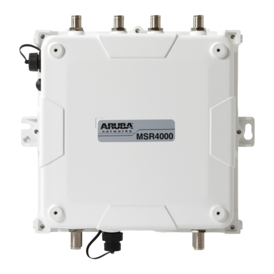
1 Product Overview There are two versions of the MSR4000, which mainly differ in the way they receive power. MSR4K43N0: PoE powered MSR4K43N3: AC powered (100-240VAC) 1.1 Interfaces Figure 1-1 Interfaces on MSR4K43N0 Antenna 2 (Radio 0) Antenna 1 (Radio 2) -
Page 12: Led Status Indicators
Console Interface AC Power Interface 1.2 LED Status Indicators The MSR4000 include visual indicators for power, link and radio status. Figure 1-3 MSR4K43N0 LED layout The table below lists the meanings of the LEDs on the MSR4K43N0. Table 1-1 MSR4K43N0 LED status indicators... - Page 13 Power to a gateway (portal) node Device has power and has found a On (Green) mesh network routing path to a gateway (portal) node Non-powered device Displays PSE power (0Ω<Rport<200Ω) or Port open output status (Rport>1MΩ) MSR4000 Installation Guide...
- Page 14 Radio 2 is providing access (SSID) On (Blue) service or backhaul (mesh) service Radio 3 is not providing either access (SSID) or backhaul (mesh) service Radio 3 Status Radio 3 is providing access (SSID) On (Blue) service or backhaul (mesh) service MSR4000 Installation Guide...
-
Page 15: Installation Preparations
Use these materials to repack and return the unit to the supplier if needed. 2.2 Preparing Installation Tools When installing MSR4000, you may need the following tools. You shall select the tools according to the actual situation. MSR4000 Installation Guide... -
Page 16: Examining The Installation Site
3. Interference must be considered in site selection. New site should avoid known interference, unless the interference is controllable. 4. Keep the MSR4000 away from places that are susceptible to high temperature, dust, harmful gas, inflammable, explosive, electromagnetic interference (high power radar, radio station and transformer), unstable voltage, heavy vibration, or loud noise. -
Page 17: Weatherproofing Connections
The following sections provide guidance on weatherproofing directly connected antennas (Figure 3-1) and cable connections (Figure 3-2). The same materials are needed for weatherproofing both types of connections but the procedure is slightly different. For weatherproofing directly connected antennas, see MSR4000 Installation Guide... - Page 18 "Weatherproofing Directly Connected Antennas" section. For weatherproofing cable connections, see "Weatherproofing Cable Connections" section. Figure 3-1 Directly connected antennas MSR4000 Installation Guide...
-
Page 19: Important Points To Remember
2. Prepare the antenna connector by cleaning and drying it. 3. Cut a 4” (100 mm) strip of electrical tape from the roll. Pre-cutting the tape into strips makes it easier to maneuver the tape around the antennas and other components of the AP’s case. MSR4000 Installation Guide... - Page 20 1. Cut a 3/4” (19 mm) strip of butyl rubber. 2. Wrap the strip of rubber around the taped connector (Figure 3-4) 3. Join the two ends by pushing them together until there is no longer a seam (Figure 3-5). MSR4000 Installation Guide...
- Page 21 1. Cut a 4” (100 mm) strip of electrical tape from the roll. 2. Where you begin wrapping depends on the orientation of the antenna. Water should flow in the opposite direction of the wrapping to prevent water from MSR4000 Installation Guide...
-
Page 22: Weatherproofing Cable Connections
Figure 3-6 Completed wrapping (antenna on top of AP) 4. Repeat this process for all connectors. 3.5 Weatherproofing Cable Connections First Wrapping of Tape 1. Prepare the antenna connector by cleaning and drying it. MSR4000 Installation Guide... - Page 23 2. Wrap the strip of rubber around the taped connector (Figure 3-8) 3. Join the two ends by pushing them together until there is no longer a seam (Figure 3-9). MSR4000 Installation Guide...
- Page 24 2. Using 3/4” (19mm) electrical tape, begin wrapping at the connector and create four layers. 3. After completing the fourth layer of tape, check your work to ensure there are no places where water can collect. If there are, you must smooth out those MSR4000 Installation Guide...
- Page 25 Figure 3-10 Completed wrapping 4. Repeat this process for all connections. MSR4000 Installation Guide...
-
Page 26: Msr4000 Installation
{M6 x30 bolt, flat washer, spring washer}x2 Step 1 Fix the solar shield on MSR4000 using the four M4 x16 bolts (with flat and spring washers) on the four screw holes of the MSR4000. (See figure below) MSR4000 Installation Guide... - Page 27 Figure 4-2 Positions of screw holes on the solar shield Step 2 Screw the two M4 x16 bolts into the holes on the back of the MSR4000. (See figure below) Figure 4-3 Positions of screw holes on the back of the MSR4000 Step 3 Fix the mounting bracket and the pair of pole anchors on the pole using four M8 x110 bolts (with flat washers, spring washers and nuts).
- Page 28 Figure 4-5 Fix the mounting bracket and the pair of pole anchors on the mounting bracket Step 4 Align the two M4 x16 bolts on the back of MSR4000 with the holes on the mounting bracket and hang the MSR4000 on the bracket.
- Page 29 Hang the two M4 x16 bolts of the back of the MSR4000 on the two holes of the mounting bracket. Step 5 Align the two installation holes on the side of the MSR4000 with the corresponding holes on the mounting bracket and then use the two M6 x30 bolts (with flat and spring washers) to fix them.
-
Page 30: Installing Msr4000 On A Wall
1) Screw the two M4 x16 bolts into the holes on the back of the MSR4000. 2) Align the two M4 x16 bolts on the back of MSR4000 with the holes on the mounting bracket and hang the MSR4000 on the bracket. - Page 31 Step 6 Fix MSR4000 1) Align the two installation holes in the MSR4000 with the corresponding holes in the wall- mounting bracket. 2) Insert the two M6 x30 bolts (with flat and spring washers) through the installation holes, and tighten the bolts.
-
Page 32: Grounding The Msr4000
Step 2 Fasten the copper lug to the grounding hole on the MSR4000 with the M4 x12 bolt and external-tooth washer. -
Page 33: Connecting The Ethernet Cable
Step 3 Water-proof the antenna connection with PVC insulation tape, adhesive insulation tape and strap. 4.5 Connecting the Ethernet cable To ensure that MSR4000 maintains Ethernet connectivity and Power over Ethernet (PoE), you must use the weatherproof connector kit and install it using the steps below. Note ... - Page 34 Insert the Ethernet cable into the narrow end of the clamp ring and pass it through the opening end of waterproof connector socket. Using a crimping tool, attach the included shielded RJ45 connector. MSR4000 Installation Guide...
-
Page 35: Connecting Power Cable
The MSR4K43N3 version needs an outdoor rated power cable to connect to a compatible AC power source. Note: The MSR4000 does not ship with any power cables; these are available as accessories and should be ordered separately. In addition to completed power cables, Aruba also offers an outdoor rated AC connector kit that can be used to connect a compatible power cable to the MSR4000. - Page 36 Step 3 Water-proof the power cable connection with PVC insulation tape, adhesive insulation tape and strap. Note Cable assembly and installation should be done by a licensed electrician only. Figure 4-15 Connecting power cable to the power interface MSR4000 Installation Guide...
-
Page 37: Note
5 Note To log onto the MSR4000 via Console port, use the setting as shown in table below: Baud Rate 115200 Data Bits Parity None Stop Bits Flow Control None Default Username and Password Username: root Password: public MSR4000 Installation Guide...
Need help?
Do you have a question about the MSR4000 and is the answer not in the manual?
Questions and answers