Friedrich MRM36Y3J Installation And Operation Manual
Hide thumbs
Also See for MRM36Y3J:
- Installation and operation manual (36 pages) ,
- Service & parts manual (135 pages) ,
- Installation and operation manual (26 pages)
Table of Contents
Advertisement
Quick Links
Advertisement
Table of Contents

Related Manuals for Friedrich MRM36Y3J


Summary of Contents for Friedrich MRM36Y3J
- Page 1 MWM36Y3J MRM36Y3J...
-
Page 3: Table Of Contents
Content Operation Notices Precautions......................1 Parts name ......................2 Screen Operation Guide Buttons on remote controller .................3 Introduction for icons on display screen ..............3 Introduction for buttons on remote controller ............4 Function introduction for combination buttons ............Operation guide ..................... Replacement of batteries in remote controller ............Emergency operation .................. -
Page 4: Precautions
Precautions Warning cause electric shock. damage. Please contact dealer when you need to repair air conditioner. . Otherwise personal injury or damage damage or personal injury. personal injury or damage. electricshock. Otherwise, it may cause personal injury or damage. Working temperature range Indoor side DB/WB( /°F) Outdoor side DB/WB( /°F) Maximum cooling 27/19(80.6/66.2) -
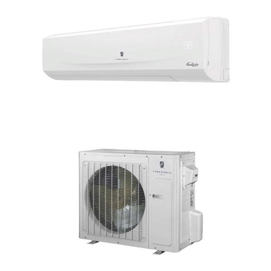
Page 5: Parts Name
Parts name Indoor Unit panel air inlet display aux.button air outlet horizontal louver display temp. indicator cooling indicator drying indicator power indicator heating indicator receiver window aux.button remote control Outdoor Unit air inlet handle handle air outlet Notice: Actual product may be different from above graphics, please refer to actual products. - Page 6 Operation of Remote Controller START / STOP Press to start or stop operation. : Press to decrease temperature setting. : Press to increase temperature setting. AUTO Press to set fan speed. MODE Press to select operation mode (AUTO/COOL/DRY/FAN/HEAT). SENSOR CLOCK Press set clock.
- Page 7 Operation of Remote Controller 17 18 19 20 MODE icon: LIGHT icon: If MODE button is pressed, is displayed by pressing the current operation mode icon LIGHT button. Press LIGHT button again to clear the display. (AUTO), ( COOL), (DRY), (FAN) or (HEAT LOCK icon:...
- Page 8 Operation of Remote Controller 17 18 19 20 SENSOR icon: EXTEND icon: is displayed when pressing the is displayed when pressing the button. Press this button SENSOR button. Press this button EXTEND again to clear the display. again to clear the display. FAN SPEED display: Press FAN button to select the desired fan speed setting (AUTO-...
- Page 9 Remote Control Instructions Remote Controller Description START / STOP Press this button to turn on the unit .Press this button again to turn off the unit. Press this button to decrease set temperature. Hold it down for 2 seconds to rapidly decrease set temperature. In AUTO mode, set temperature is not adjustable.
- Page 10 Remote Control Instructions TIMER ON : Press this button to initiate the auto-ON timer. To cancel the auto-timer program, simply press this button again. After pressing this button, disappears and "ON "blinks . 00:00 is displayed for ON time setting. Within 5 seconds, press + or - button to adjust the time value. Every press of either button changes the time setting by 1 minute.
- Page 11 Remote Control Instructions SLEEP: Press this button to go into the SLEEP operation mode. Press it again to cancel this function. This function is available in COOL or DRY mode to maintain the most comfortable temperature for you. LIGHT: Press LIGHT button to turn on the display's light and press this button again to turn off the display's light.
-
Page 12: Emergency Operation
Emergency operation If remote controller is lost or damaged, please use auxiliary button to turn on or turn off the air conditioner. The operation in details are as below: conditioner. When the air conditioner is turned on, it will operate under auto mode. - Page 13 Clean and maintenance Open panel water (below clean it, and then to dry. panel cover tightly. Note:...
- Page 14 Clean and maintenance 1. Check whether air inlets and air outlets are blocked. 2. Check whether circuit break n good condition. 4. Check whether mounting bracket for outdoor unit is damaged or corroded. If yes, please contact dealer. 5. Check whether drainage pipe is damaged. 1.
- Page 15 Check items Solution Indoor unit Select proper angle and point the remote controller at the remote controller?
- Page 16 Check items Solution Mist Please exceeds the set temperature range Cooling range? range.
- Page 17 Check items Solution Air conditioner operates abnormally Outdoor Crack...
- Page 18 Error Code Error code Above indicator diagram is only for reference. Please refer to actual product for the actual Indoor indicator and position. Error code Troubleshooting Warning...
-
Page 19: Installation Dimension Diagram
Installation dimension diagram Space to the wall At least At least Space to the wall Drainage pipe... -
Page 20: Tools For Installation
Tools for installation 1 Level 2 Screw driver 3 Impact drill 5 Pipe expander 4 Drill head 6 Torque wrench 8 Pipe cutter 7 Open-end wrench 9 Leakage detector 10 Vacuum pump 14 Measuring tape Note: Selection of installation location Indoor unit Basic requirement Installing the unit in the following... -
Page 21: Requirements For Electric Connection
Requirements for electric connection Safety precaution 1. Must follow safety regulations when installing the unit. circuit break . 3. Make sure the power supply matches with the requirement of air conditioner. nstall proper power supply cables before using the air conditioner. 5. -
Page 22: Installation Of Indoor Unit
Installation of indoor unit Step one: choosing installation location Step two: install Step three: open piping hole 1. Choose the position of piping hole according to the direction of outlet pipe. The position of piping hole should be a little lower than the wall-mounted frame, shown as below. - Page 23 Installation of indoor unit Indoor outdoor Note: Φ 5-10 Step four: outlet pipe 1. The pipe can be led out in the 2. When select leading out the pipe direction of right, rear right, left or from left or right, please cut off the rear left.
- Page 24 Installation of indoor unit Hex nut diameter Tightening torque (N . m) open-end wrench 15~20 30~40 40~55 pipe torque wrench 60~65 70~75 indoor pipe Step six: install drain hose 1. Connect the drain hose to the outlet pipe of indoor unit. drain hose outlet pipe 2.
- Page 25 Installation of indoor unit 2. Make the power connection wire go cable-cross hole through the cable-cross hole at the back of indoor unit and then pull it out from the front side. power connection wire 3. Remove the wire clip; connect the power connection wire to the wiring terminal with wire clip.
- Page 26 Installation of indoor unit Step eight: bind up pipe 1. Bind up the connection pipe, power drain hose connection pipe band cord and drain hose with the band. indoor and outdoor power cord indoor unit pipe indoor power cord liquid pipe 3.
-
Page 27: Installation Of Outdoor Unit
Installation of outdoor unit 1. Select installation location the outdoor unit on the selected location with expansion screws Note: installing the outdoor unit. Make sure the support can withstand at least four times of the unit weight. joint. , 6 expansion screws are needed; for the unit with cooling capacity of , 8 expansion screws are needed at least... - Page 28 Installation of outdoor unit foot holes 1. Place the outdoor unit on the support. 2. Fix the foot holes of outdoor unit with bolts. foot holes Step four: connect indoor and outdoor pipes 1. Remove the screw on the right handle of outdoor unit screw and then remove the handle.
- Page 29 Installation of outdoor unit 1. Remove the wire clip; connect the power connection wire and signal control wire (only for cooling and heating unit) to the wiring terminal according to the color; N(1) blue brown yellow- (white) black blue green (white) yellow- brown...
- Page 30 Installation of outdoor unit Step six: neaten the pipes 1. The pipes should be placed along the wall, bent reasonably and hidden Min. bend t pipe is wall 2. If the outdoor unit is higher than the , you must set a U-shaped curve in the pipe before pipe goes into the room, in order to prevent rain from getting U-shaped curve...
- Page 31 Remove the valve caps on the liquid valve and gas valve and the nut of refri Connect the charging hose to the refri liquid valve gas valve refrigerant charging valve cap of refrigerant charging vacuum pump close open...
-
Page 32: Vacuum Pumping
Vacuum pumping Use vacuum pump Remove the valve caps on the liquid valve and gas valve liquid valve and the nut of refri gas valve Connect the charging hose to the refri refrigerant charging valve cap nut of refrigerant charging vacuum pump close open... -
Page 33: Check After Installation
Check after installation Items to be checked Possible malfunction The unit may drop, shake or emit noise. It may cause condensation and water dripping. It may cause condensation and water s water drain well? dripping. Is the voltage of power supply It may cause voltage marked on the nameplate? Is electric wiring and pipeline installed... -
Page 34: Pipe Expanding Method
Pipe expanding method Note: Improper pipe expanding is the main cause of refrigerant leakage. Please expand the pipe according to the following steps: A: Cut the pipe E: Expand the port the distance of indoor unit and hard outdoor unit. mold expander pipe... - Page 36 Friedrich Air Conditioning Co. 10001 Reunion Place, Suite 500 • San Antonio, Texas 78216 1.800.541.6645 www.friedrich.com 66129922128...
Need help?
Do you have a question about the MRM36Y3J and is the answer not in the manual?
Questions and answers