Table of Contents
Advertisement
Quick Links
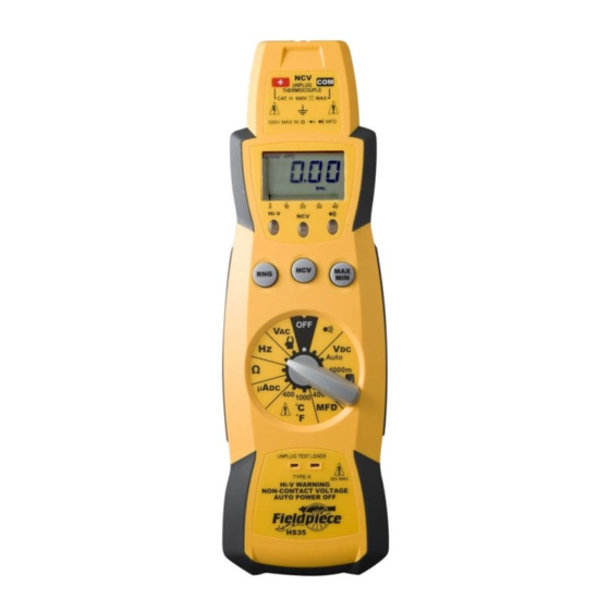
AUTO-RANGING
DIGITAL STICK
METERS:
HS35
HS36
Function Legend
Continuity
VDC
Volts DC
MFD
Capacitance
°C/°F
Temperature
ADC
Microamps DC
Resistance
Hz
Frequency
VAC
Volts AC
OPERATOR 'S MANUAL
Non-contact voltage
With the red NCV tab on the tip of the meter close
to an AC voltage, press and hold the NCV button.
The NCV LED will light and the beeper will beep. The
closer you get to AC voltage, the louder the beep.
The NCV function is sensitive enough to detect
24VAC on thermostats.
Hi voltage indicator
In any VAC/VDC range, when you touch a voltage
greater than 30V, the beeper will beep and the red Hi-
V LED will blink. BE CAREFUL!
Microamps
For measuring the flame diode current in a heater
control.
Capacitance
For
motor-start
and
motor-run
Disconnect the capacitor from power first. Short the
terminals to discharge the capacitors. Disconnect
any resistors that might be between the terminals of
the capacitor.
MIN/MAX
Press MIN/MAX once to begin recording MIN and
MAX. Press MIN/MAX to select current reading's MIN
or MAX. Hold down for 2 seconds to exit MIN/MAX
function.
Temperature
Plug any K-type thermocouple directly into the
meter to measure temperature. Temperature meas-
urement will be accurate even in fast changing envi-
ronments because of excellent temperature compen-
sation. One thermocouple is included. No adapter is
required.
Backlight (HS36)
Press the
button to activate the backlight for
approximately 60 seconds.
For your safety...
General: Disconnect the test leads before opening
the case. Inspect the test leads for damage to the
insulation or exposed metal. Replace if suspect.
Never ground yourself when taking electrical meas-
urements. Do not touch exposed metal pipes, outlets,
fixtures, etc., which might be at ground potential.
Keep your body isolated from ground by using dry
clothing, rubber shoes, rubber mats, or any approved
insulating material. When disconnecting from a cir-
cuit, disconnect the "RED" lead first, then the com-
mon lead. Work with others. Use one hand for test-
ing. Turn off power to the circuit under test before cut-
ting, unsoldering, or breaking the circuit. Keep your
fingers behind the finger guards on the probes. Do
not measure resistance when circuit is powered. Do
not apply more than rated voltage between input and
ground.
All voltage tests: All voltage ranges will withstand
up to 600V. Do not apply more than 600VDC or
600VAC.
AC tests: Disconnect the meter from the circuit
before turning any inductor off, including motors,
transformers, and solenoids. High voltage transients
can damage the meter beyond repair. Do not use
during electrical storms.
Maintenance
Clean the exterior with clean dry cloth. Do not use
liquid.
Battery replacement: When the multimeter dis-
plays "
" the battery must be replaced. Disconnect
and unplug leads, turn meter off, and remove the bat-
tery cover. Replace the battery with a NEDA type
1604 9V battery.
True RMS (HS36)
Digital multimeters use two different types of AC
sensing. The most common is average sensing, nor-
malized to a true RMS value of a sine wave. The
other is true RMS sensing. The actual true RMS
value is sensed for a wave form within the limits of
the crest factor. Either sensing method will give the
same results on a clean sine wave but they may dif-
fer on a non-sinusoidal waveform.
Field F calibration
For accuracies of 1 F, calibrate to a known tem-
perature. A glass of stabilized ice water is very close
to 32 F (0°C) and is usually very convenient but any
known temperature can be used.
1. Select the 400 F range.
2. Remove back case and hold the battery in place
capacitors.
with a rubber band so terminals are touching.
3. Stabilize a large cup of ice water.
4. Immerse the thermocouple probe and let it stabi-
lize.
5. Adjust VR3 (lower right corner of PCB) to get
close to 32 F (0°C) then adjust VR2 (left of VR3)
to get within 0.1 F (0.05°C) of 32 F (0°C).
6. To calibrate in C, close the jumper that is to the
left of VR3.
Disable auto off
Set to OFF position, press and hold RNG (HS35)
or MIN/MAX (HS36) button while turning rotary dial
to desired range position. Release the button when
LCD displays normally. Note: "APO" annunciator will
be missing from the display. The Auto Power Off
mode is on when "APO" indicated on the display.
Attach to Fieldpiece accessory head
Connect your Fieldpiece accessory head directly
to the top of HS series and switch to range indicated
by head. Visit www.fieldpiece.com for more info.
Limited warranty
This meter is warranted against defects in materi-
al or workmanship for one year from date of pur-
chase. Fieldpiece will replace or repair the defective
unit, at its option, subject to verification of the defect.
This warranty does not apply to defects resulting
from abuse, neglect, accident, unauthorized repair,
alteration, or unreasonable use of the instrument.
Any implied warranties arising from the sale of a
Fieldpiece product, including but not limited to
implied warranties of merchantability and fitness for a
particular purpose, are limited to the above.
Fieldpiece shall not be liable for loss of use of the
instrument or other incidental or consequential dam-
ages, expenses, or economic loss, or for any claim of
such damage, expenses, or economic loss.
State laws vary. The above limitations or exclu-
sions may not apply to you.
Service
Return any defective HS35/36 to Fieldpiece for
warranty service along with proof of purchase.
Contact Fieldpiece for out of warranty repair charges.
www.fieldpiece.com
Symbols used:
Caution, risk of electric shock
!
Caution, refer to manual.
Ground
Double insulation
Using & storing test leads
Because the wire insulation is silicone the leads
will stay flexible in cold weather and will not melt if
bumped by a soldering iron.
Disconnect top half of test lead and plug tip direct-
ly into meter to make voltage testing easy. Use with
included alligator clip (ASA2) as shown for even eas-
ier operation.
For convenient lead storage, wrap the leads as
shown. Pull leads around front between overhanging
tips, twist, and pull over one of the lead plugs.
v08
Advertisement
Table of Contents

Related Manuals for Fieldpiece HS35


Summary of Contents for Fieldpiece HS35
- Page 1 Turn off power to the circuit under test before cut- Fieldpiece shall not be liable for loss of use of the ting, unsoldering, or breaking the circuit. Keep your instrument or other incidental or consequential dam- fingers behind the finger guards on the probes.
- Page 2 For DC voltage, set the meter to the VDC parame- what's being meas- ter instead of VAC as shown above. Connect to Fieldpiece accessory heads by simply ured. For all ranges choose a range just above the value attaching them to the top of meter (1) or attach you expect.
Need help?
Do you have a question about the HS35 and is the answer not in the manual?
Questions and answers