Advertisement
Quick Links
Safety Information:
White Light and IR Variants (850nm & 940nm)
Caution – Risk Group 2. Avoid Exposure / use protection.
See Safety Information in FULL Instruction Guide for details.
Box Contents:
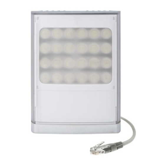
VARIO2 Illuminator with 35° ILS fitted, spare 60° beam angle ILS, User Guide
(ILS: Interchangeable Lens System)
Optional Accessories: Remote Controller for additional programming,
angle ILS,
Factory Default Set-Up:
ILS, Max 100% Power
Telemetry Input – closed, Photocell sensitivity – MID
Status LEDs – ON, No PIN Set
Unit will change from Programming Mode to Operating Mode after 7 Days (or 30
minutes after last press of manual buttons)
VARIO2 Specifications Table:
i16
100W
Consumption
max
Input
Weight
3.1kg (6.8lbs)
Number of
LED's
Environment
180 x 277 x 75mm
Dimensions
Cable Length
2.5m
w16
i8
84W
46W
max
max
24V AC/DC
12/24V AC/DC
1.65kg (3.61lbs)
48
IP66
135 x 180 x 68mm
7"x11"x2.9"
(5"x7"x3")
2.5m
2.5m
Quick Start
, Bracketry
w8
i6
42W
25W
max
max
12/24V AC/DC
950g (2.1lbs)
24
12
IP66
100 x 135 x 66m
4"x5"x2.5")
2.5m
2.5m
i4
w4
i2
13W
24W
10W
max
max
max
12/24V AC/DC
600g (1.3lbs)
9
12
6
IP66
75 x 100 x 64mm
3"x4"x2.5")
2.5m
2.5m
2.5m
w2
11W
max
6
IP66
2.5m
Advertisement

Subscribe to Our Youtube Channel
Related Manuals for Raytec VARIO 2 VAR2-w8-1


Summary of Contents for Raytec VARIO 2 VAR2-w8-1
- Page 1 Quick Start Safety Information: White Light and IR Variants (850nm & 940nm) Caution – Risk Group 2. Avoid Exposure / use protection. See Safety Information in FULL Instruction Guide for details. Box Contents: VARIO2 Illuminator with 35° ILS fitted, spare 60° beam angle ILS, User Guide (ILS: Interchangeable Lens System) Optional Accessories: Remote Controller for additional programming, angle ILS,...
- Page 2 Wiring: Mount Illuminator Connect Illuminator to low voltage input 12-24V AC/DC IMPORTANT: For Vario 16 variants : 24V only AC/DC 3. Complete configuration, wiring and final set-up using manual push buttons on the illuminator or VARIO Remote Controller (VRC) - VRC is an optional accessory Black Wire = Negative (+ve) Red Wire = Positive (-ve)
- Page 3 Manual Button Operation Buttons are accessed by removing the base plate at the bottom of the unit. The number of button pushes indicated below are based on the user starting with the illuminator in either programming or operating mode. Action Step1 : Step 2 : Comment...
- Page 4 Action Step1 : Step 2 : Comment Required LHS Button RHS Button Disable / 1 x Long Flashing Push to Disable – Red Buttons will be Enable Push (4s), Amber cycle Enable - Green Disabled 30 Manual then 2 x Disable / minutes after this Buttons...
- Page 6 Remote Control Operation PIN set and Manual Button Disable / Enable Action Available Step1 Step 2 Comment Required Mode Disable Programming Press Solid Green Flashing Amber to Illuminator will go Remote Mode <Disable Solid Amber to Off to Operating Remote Mode.
- Page 7 LED Status Indicators: Programming Mode and Operating Mode On first power up (Factory Default) the illuminator automatically enters Programming Mode. It will then time out automatically after 7 Days to Operating Mode unless the user actively disables the remote control or uses the manual buttons in which case Operating Mode will start 30 minutes after the last manual button press.
- Page 8 RESET: Settings Re-set : Pressing and holding the RESET BUTTON on the remote control or using the manual buttons to complete a RESET will restore the factory settings to the illuminator. Note : It will not remove a PIN if one is present. Full Re-set : Re-cycling the power whilst pressing both manual buttons will restore factory settings and remove a PIN if one is present.
-
Page 9: Table Of Contents
Contents : Page 2 Box Contents and Safety Information Page 3 Short Guide and Factory Defaults Page 6 LED Status Indicators – Feedback System Page 8 VARIO Remote Controller (VRC) Page 10 PIN Function Detail Page 12 Manual Control Buttons Page 17 Disabling Manual Buttons Page 18... - Page 10 Box Contents : VARIO2 Illuminator , spare 60° beam angles ILS (ILS: Interchangeable Lens System) Accessories (Optional) :VARIO Remote Control for additional Programming; and 120 ; Bracketry VARIO2 Enhancements • Increased Distance • Default time for illuminator to go into Operating Mode reduced •...
- Page 11 Installation Steps: beam width. 4 for detailed instructions 2. Mount Illuminator -24V AC/DC (For Vario 16 variants : 24V AC or DC only) buttons on the illuminator or VARIO Remote Controller (VRC) - VRC Photocell Black Wire Red Wire Cable Breather Gland is unable to shorten and re-use...
- Page 12 Factory Default Set-Up: VARIO2 Complete Set up and Installation Step 1. Important Note :...
- Page 13 Step 2. Mounting Illuminator VARIO2 is delivered as standard with bracket at the bottom of the unit. This can be moved to the top of the unit if required. See page 18 for optional brackets Step 4. Telemetry Input (Orange & Purple) As default the telemetry input will be wired together so that the unit turns on/off automatically via the photocell.
-
Page 14: Led Status Indicators- Feedback System
Step 5. Photocell following output (White & Yellow) Volt free output - normally open (day) to normally closed (night). Connect direct to camera if required to control switchover of day/night cameras. Step 6. Programme using optional VARIO Remote Control (VRC) or the manual control buttons. - Page 15 Programming Mode and Operating Mode On powering up the illuminator, it automatically enters programming mode to allow the user to adjust set-up and operation. The programming mode automatically times out after 7 Days or until the user actively disables the remote control or the unit times out 30 minutes after any press of the manual buttons on the illuminator.
-
Page 16: Vario Remote Controller (Vrc)
VARIO Remote Controller (VRC) : Optional Accessory Full instructions provided with VRC when supplied Note : Reset button will not remove a PIN if one is present Note : Unless detailed as part of the functionality, if an invalid or blocked command is attempted, both LEDs will flash RED... - Page 17 Extra VRC Functionality : - PIN Function For extra security VARIO2 allows a PIN (Personal Identification Number) to be set for each lamp The PIN is set by using the Vario Remote Control (VRC). There are five buttons / characters on the remote that can be used for this purpose.
-
Page 18: Pin Function Detail
PIN Function Detail : The PIN is set by using the Vario Remote Control (VRC). There are five buttons / characters on the remote that can be used for this purpose. They are Power 5, Power 1, Min Photocell (Smallest moon), Max Timer (Full Red Circle) &... - Page 19 To delete an existing PIN you first need to be in Programming Mode by entering your PIN. Once in Programming Mode, press STATUS BUTTON for 4 seconds to go into PIN set mode. LHS LED will flash RED / GREEN and RHS LED FLASHING RED.
-
Page 20: Manual Control Buttons
Manual Control – Buttons : The two manual control buttons gives a wide selection of user control : 1. Power Control – 100%, 80%, 60%, 40%, 20% of maximum. (Factory Default is 100%) 2. Photocell Control – 3 levels, 25 Lux on, 50 Lux off, 10 Lux on 30 Lux off, 5 Lux on 15 Lux off and photocell disable. - Page 21 Manual buttons can be accessed by removing the base cover of the illuminator The buttons are active in both programming mode and operating mode regardless of whether a PIN is present or not unless you have previously disabled the manual buttons As soon as manual button mode is entered by pressing the Left Hand Button, the standard LED indicators will be disabled and will indicate a new set of information, Standard LED indicators are enabled after exiting...
- Page 22 Manual Setting / Level Indication using RHS Button : The RHS BUTTON will only have an effect if you have selected a mode using LHS Button – pressing RHS Button without previously pressing LHS Button will have no effect on the Illuminator operation – it is used to control the setting for the mode chosen by LHS Button When you select a mode using LHS BUTTON, the LHS LED will confirm which mode you are in and RHS LED will show the current setting / level...
- Page 23 Illuminator Settings Mode Detail : Enter this mode by a momentary press of LHS button to turn LHS LED solid RED. Pressing the LHS button again will turn the LED solid GREEN and pressing a third time will turn the LED solid AMBER. Each of these colours indicates which setting mode you are in.
- Page 24 Illuminator Security Modes Detail : Enter this mode by a long 4 second press of LHS button to turn LHS LED Flashing RED. Pressing the LHS button again momentarily will turn the LHS LED Flashing GREEN and pressing a third time momentarily will turn the LHS LED Flashing AMBER.
-
Page 25: Disabling Manual Buttons
NOTE – If no buttons are pressed within 2 minutes the illuminator times out and returns to the previous mode it was in – either Programming Mode or Operating Mode. Disabling the Manual Buttons : If the Illuminator is in Operating Mode, once the disable manual buttons command is executed the buttons will be disabled after 30 minutes. - Page 26 Power Up Functionality : After power is supplied to the unit : If no PIN is present the Illuminator will go into Programming Mode for 7 Days and then will default to Operating Mode - During this time if the remote is used to change settings the illuminator will still default into Operating Mode after 7 Days from the power up (unless the remote disable button is used to change the illuminator to Operating Mode)
-
Page 27: Standard Bracketry
Standard Bracketry : Supplied with the Product (Model Dependant) not to scale, dimensions rounded to nearest mm) Optional Bracketry ( not to scale - other Bracketry also available VUB-Pole VUB-Wall VUB-Plate VUB-PSU Plate Wall Mount PTZ Mount Dome Mount Pole Mount... - Page 28 VARIO2 Specifications Table : Infra-Red Series & White-Light Series 500m 250m 350m 180m 200m 144m 110m 10° (1640ft) (1148ft) (591ft) (656ft) (472ft) (361ft) (256ft) (197ft) (820ft) 250m 125m 165m 120m 35° (820ft) (541ft) (312ft) (394ft) (256ft) (213ft) (177ft) (131ft) (410ft) 135m 60°...
- Page 29 VARIO2 Troubleshoot : Ensure all tests are undertaken by a qualified, trained engineer. Ensure safe working practices are followed at all times. Step 1: Basics • Check polarity of illuminator connection red=+ve, black=-ve • Ensure power is 12-24V AC or DC (For Vario 16 variants : 24V AC or DC only) •...
- Page 30 Step 3: Set up camera, lens, and illumination • Check model number to Ray performance specification to ensure required distance is achievable; Check unit is set to max power Check orientation of unit and ensure it is pointing in correct direction Check angle of unit (Interchangeable lens) –...
- Page 31 In extreme sunlight conditions, distance between remote and unit may need to be reduced Programming may be disabled. Enter PIN to retrieve control or RESET illuminator using one of the two RESET modes. Battery failure. Check battery on remote (CR2025). Test 3 volt battery, replace if necessary.
Need help?
Do you have a question about the VARIO 2 VAR2-w8-1 and is the answer not in the manual?
Questions and answers