
Related Manuals for UTECH VS2000

Summary of Contents for UTECH VS2000
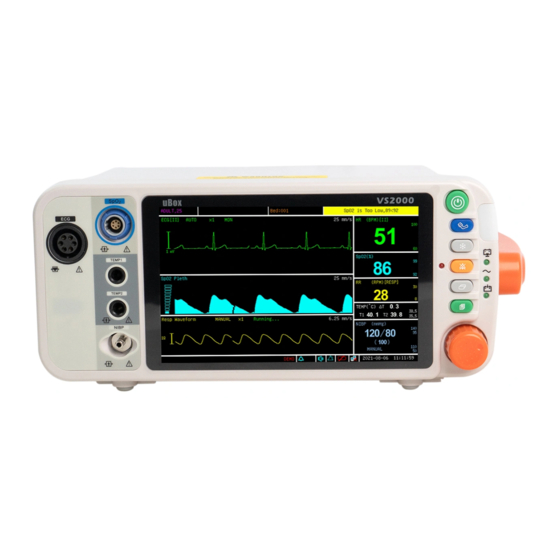
- Page 1 VS2000 Vital Signs Monitor Operation Manual - English Version 1.0, January 2011 © 2011 UTECH Co., Ltd . All rights reserved.
-
Page 3: Table Of Contents
4.4 Basic Operation ..............4-2 4.5 Systems Setup ..............4-3 4.5.1 Time Setup ..................4-3 4.5.2 Unit Setup ..................4-4 4.5.3 Net Setup ..................4-4 4.5.4 Volume Setup ................4-5 4.5.6 LCD Brightness Setup ..............4-6 VS2000 Vital Signs Monitor Operation Manual... - Page 4 7.4 Attaching the Patient ............7-2 7.5 Choosing the Waveform Settings ......... 7-4 7.5.1 Access the ECG Waveform Menu ..........7-4 7.5.2 Change the Primary ECG Lead ............7-4 7.5.3 Choose the Waveform Size ............7-5 VS2000 Vital Signs Monitor Operation Manual...
- Page 5 9.6.2 Choose the Interval for Automatic NIBP Measurements .... 9-7 9.6.3 Assist Venous Puncture ..............9-8 9.7 Measuring Non-invasive Blood Pressure (NIBP) ..... 9-9 9.7.1 Manual NIBP Mode ..............9-9 9.7.2 Auto NIBP Mode ................9-9 9.7.3 STAT NIBP Mode ................. 9-10 VS2000 Vital Signs Monitor Operation Manual...
- Page 6 13.2 Long-term Storage ............13-2 13.3 Operator's Troubleshooting Chart ........13-2 13.4 Maintenance Menu ............13-4 13.4.1 Access the Maintenance Menu ..........13-4 13.4.2 Back to Factory Default Values..........13-5 13.4.3 Using the Demo Mode .............. 13-5 VS2000 Vital Signs Monitor Operation Manual...
- Page 7 15.7 Respiration Rate (RESP) ............ 15-3 15.8 Temperature (TEMP) ............15-4 15.9 Default Alarms Limits ............15-4 15.10 Power Requirement ............15-4 15.11 Dimensions ..............15-4 15.12 Environmental ..............15-5 15.13 Equipment Classification ..........15-5 VS2000 Vital Signs Monitor Operation Manual...
- Page 8 Table of Contents This Page is Intentionally Left Blank! VS2000 Vital Signs Monitor Operation Manual...
-
Page 9: Warranty And Service Information
Information contained in this document is copyrighted by Utech Co., Ltd. and may not be duplicated in full or part by any person without prior written approval of UTECH Co., Ltd . Its purpose is to provide the user with adequately detailed documentation to efficiently install, operate, maintain and order spare parts for the device supplied. -
Page 10: Disclaimer Of Warranties
Warranty and Service Information consent of Utech Co., Ltd. and seller shall not be liable in any event for incidental or consequential damage. This warranty is not assignable. Warranties are subject to change. Please contact Utech Co., Ltd. for current warranty information. - Page 11 Box and inserts should be in original condition. If original shipping material in good condition is not available, it should be purchased from Utech Co., Ltd. Damages occurring in transit in other than original shipping containers are the responsibility of the shipper.
- Page 12 Warranty and Service Information This Page is Intentionally Left Blank! VS2000 Vital Signs Monitor Operation Manual...
-
Page 13: Chapter 1: Introduction
1.3 Definition of Symbols SYMBOLS DEFINITION Attention, see in instructions for use Type BF Defibrillation Defibrillator-proof type CF equipment NIBP Start/ Stop Key Freeze Key Alarm Silence Battery Supply LED VS2000 Vital Signs Monitor Operation Manual... -
Page 14: Warning Information
Evidence that liquid has been allowed to enter the monitor voids the warranty. WARNING! This device must be used in conjunction with clinical signs and symptoms. This device is only intended to be an adjunct in VS2000 Vital Signs Monitor Operation Manual... - Page 15 WARNING! Medical electrical equipment, including this device, needs special precautions regarding electro-magnetic compatibility (EMC) and needs to be installed and put into service according VS2000 Vital Signs Monitor Operation Manual...
- Page 16 Ensure that hands are thoroughly dry before handling the AC power supply. WARNING! Do not place the monitor in the patient's bed. Do not place the monitor on the floor. VS2000 Vital Signs Monitor Operation Manual...
- Page 17 These batteries are not user replaceable. Refer servicing to qualified personnel. CAUTION! Pressing front panel keys with sharp or pointed instruments may permanently damage the keypad. Press the front panel keys only with your finger. VS2000 Vital Signs Monitor Operation Manual...
- Page 18 ECG signal. NOTE! Follow institutional standards when applying ECG electrodes. Silver/Silver Chloride disposable electrodes are strongly recommended to avoid polarization effects that result in large input offset potentials. Use of "squeeze bulb" type electrodes is VS2000 Vital Signs Monitor Operation Manual...
- Page 19 WARNING! Do not autoclave, ethylene oxide sterilize, or immerse the sensors in liquid. Evidence that liquid has been allowed to enter the monitor voids the warranty. WARNING! Use only SpO sensors supplied with, or specifically intended VS2000 Vital Signs Monitor Operation Manual...
- Page 20 Non-invasive Blood Pressure Warnings, Cautions, and Notes WARNING! Blood pressure measurements may be inaccurate if cuffs and/or hoses other than those specified by Utech Co., Ltd. are used. WARNING! Repeated use of STAT mode for periods longer than 15 minutes should be avoided to reduce the patient's risk for soft tissue or nerve damage.
- Page 21 NOTE! Systolic and diastolic blood pressure measurements determined with this device are equivalent to those obtained by the trained observer using the cuff/stethoscope auscultation method. VS2000 Vital Signs Monitor Operation Manual...
- Page 22 Chapter 1: Introduction NOTE! Mean arterial blood pressure measurements determined with this device are equivalent to those obtained by an intra-arterial blood pressure measurement device as determined by Utech Co., Ltd. Respiration Rate Warnings, Cautions, and Notes WARNING! Respiration monitoring is not recommended on active patients.
-
Page 23: Chapter 2: Intended Use And General Information
The monitor provides continuous five-lead ECG processing, with standard lead selections, and filtering from electrocautery discharge. The ECG measured value (HR) and primary lead selection are displayed in the ECG parameter box, and an ECG waveform is continuously displayed. VS2000 Vital Signs Monitor Operation Manual... - Page 24 Temperature (TEMP) Two independent channels of temperature (T1 and T2) monitoring are available. Each channel is compatible with Utech Co., Ltd. YSI 400-series disposable temperature sensors, or equivalent. The measured value for each temperature channel (T1 and T2) is displayed in the TEMP parameter box.
-
Page 25: Chapter 3: Controls And Features
Patient name and bed number will be shown here. Information Alarm Status Shows active alarm events. Main Menu The main menu provides a means of changing monitor settings, such as alarm limits and patient information, and VS2000 Vital Signs Monitor Operation Manual... - Page 26 (such as HR or SpO ) is Values displayed. The value may be derived or calculated. Dashes (- - -) in place of a numeric measured value indicate that the measurement is invalid or unavailable. VS2000 Vital Signs Monitor Operation Manual...
-
Page 27: Keys
Use this key to switch between the four main Mode Key display modes: 1 ECG mode, 3 ECG mode, oxyCRG mode and the huge digit mode. Press it to enter or exit the main menu. Menu Key VS2000 Vital Signs Monitor Operation Manual... -
Page 28: Left Panel
(PR) will be displayed when the sensor is attached (SpO to the patient. If the temperature is installed on your monitor, the Dual TEMP parameter box will appear on the display when Temperature VS2000 Vital Signs Monitor Operation Manual... -
Page 29: Back Panel
WARNING! Do not plug the monitor into an outlet controlled by a wall switch. USB Connector Network Connect to the central monitor. Interface Air Vents The monitor has air vents at the top of the back VS2000 Vital Signs Monitor Operation Manual... -
Page 30: Internal Battery
When the monitor is connected to AC power, the internal battery charges whether the monitor is on or off. The Battery Charge LED flashes while the battery is charging; it is steady when the VS2000 Vital Signs Monitor Operation Manual... - Page 31 NOTE! Battery charge time will be increased at elevated temperatures (temperatures above 30 degrees Celsius). NOTE! A fully charged battery will last 2 to 3.5 hours, depending on monitor usage. VS2000 Vital Signs Monitor Operation Manual...
- Page 32 Chapter 3: Controls and Features This Page is Intentionally Left Blank! VS2000 Vital Signs Monitor Operation Manual...
-
Page 33: Chapter 4: Setting Up The Monitor
2. Check the monitor's AC rating. Check the monitor's AC rating plate to ensure the nominal voltage at your installation site matches the monitor's rating. a. If the AC rating is not correct, do not use the monitor. Contact your authorized repair center for help. VS2000 Vital Signs Monitor Operation Manual... -
Page 34: Basic Operation
Review the trend data, graph and alarms stored on the monitor. Patient Select patient type, sex, add patient name, age and bed number. System Setup system information. Maintenance Back to default settings and conduct some maintenance VS2000 Vital Signs Monitor Operation Manual... -
Page 35: Systems Setup
4. Push the rotary knob to select the option. Turn the rotary knob to increase or decrease the value. Press it again to move out. 5. Turn the rotary knob to “OK” or “Cancel” to save or delete your settings. VS2000 Vital Signs Monitor Operation Manual... -
Page 36: Unit Setup
(kPa). The default setting is mmHg. •kPa = mmHg X 0.133 •mmHg = kPa / 0.133 4. Turn the rotary knob to “OK” or “Cancel” button and push to save or delete your settings. 4.5.3 Net Setup VS2000 Vital Signs Monitor Operation Manual... -
Page 37: Volume Setup
When an alarm occurs (and alarm silence is not enabled), the alarm tones will sound at the chosen volume. The default alarm and pulse volume settings are the fourth level. You cannot set the alarm volume to OFF. Figure 4.5: Volume Setup VS2000 Vital Signs Monitor Operation Manual... -
Page 38: Lcd Brightness Setup
3. Push the rotary knob to access the LCD setup submenu and turn the knob to highlight the brightness and push to select. 4. Turn the knob to increase or decrease the level of brightness and push it to exit. VS2000 Vital Signs Monitor Operation Manual... -
Page 39: Power Setup
4. Turn the rotary knob to “OK” or “Cancel” button and push it to save or delete your settings. 4.5.8 Language Setup There are two languages available in this monitor: Chinese and English. VS2000 Vital Signs Monitor Operation Manual... -
Page 40: Set Patient Information
If there is information needs to be entered, push the rotary knob and then the on-screen keyboard will pop up. Figure 4.9: On-screen Keyboard BUTTONS INSTRUCTION Spacebar. Press it when a space is needed. Press this key to access the character board. VS2000 Vital Signs Monitor Operation Manual... -
Page 41: Patient Setup
John Smith. Bed Number Enter the patient’s bed number, for example: ICU007. Choose Male or Female. Enter the patient’s age, for example: 25 Patient Type Choose the patient’s type: ADULT, PEDIATRIC and NEONATE. VS2000 Vital Signs Monitor Operation Manual... -
Page 42: Display Setup
There are four main fixed display modes, and you can switch between them by pressing the Mode key. a). 1 ECG Display Mode b). 3 ECG Display Mode c). Huge Digit Display Mode d). oxyCRG Display Mode 4-10 VS2000 Vital Signs Monitor Operation Manual... -
Page 43: Customize Display Modes
5. Turn the rotary knob to highlight “Not Save”, push to select and turn knob to choose a format such as Format 1 to save your settings. 6. Turn the rotary knob to “OK” or “Cancel” button and push it to save or delete your settings. VS2000 Vital Signs Monitor Operation Manual 4-11... - Page 44 Chapter 4: Setting up the Monitor This Page is Intentionally Left Blank! 4-12 VS2000 Vital Signs Monitor Operation Manual...
-
Page 45: Chapter 5: Monitoring The Patient
Display Setup function and adjust the settings of each waveform. Push and turn the rotary knob on the monitor to move the cursor. Highlight the waveform channel and push the knob to access the waveform menu in the VS2000 Vital Signs Monitor Operation Manual... -
Page 46: Adjust The Parameter Box Settings
For a list of default alarm limits, see Chapter 15: Specifications. WARNING! Verify that alarm limits are clinically appropriate for your patient and adjust according to institutional policy. VS2000 Vital Signs Monitor Operation Manual... -
Page 47: Use These Features As Needed
2. The alarming action will cease when the measured value is once again within the alarm limits. Your monitor will either automatically stop alarming as soon as the measured value returns to within the alarm limits, or it will require VS2000 Vital Signs Monitor Operation Manual... -
Page 48: Nibp Mode
NIBP parameter box and push to select. 2. Highlight the test mode and push the rotary knob select. 3. Turn the rotary knob to choose a mode (Auto, Manual, or Stat), and push VS2000 Vital Signs Monitor Operation Manual... -
Page 49: Freeze Mode
ECG • Heart Rate • ST b. Oximetry • Oxygen saturation (SpO • Pulse rate, when SpO is the selected heart rete source c. Non-invasive blood pressure (NIBP) (systolic, diastolic, mean) VS2000 Vital Signs Monitor Operation Manual... -
Page 50: Viewing Stored Trend Data
Any value over the limit is not valid. Table Select this option to access the trend table display. 2. Review Trend Table VS2000 Vital Signs Monitor Operation Manual... - Page 51 4. Review Alarms The user can review 1000 alarm records. In the review submenu, highlight the “Alarm” and push the rotary knob to select. The monitor will display the stored alarms for all the parameters. VS2000 Vital Signs Monitor Operation Manual...
- Page 52 Chapter 5: Monitoring the Patient This page is intentionally left blank! VS2000 Vital Signs Monitor Operation Manual...
-
Page 53: Chapter 6: Alarms
A medium priority alarm sound consists of two bursts of three single tones that repeats every 18 seconds. The alarm message will be displayed in the alarm status bar with a yellow flashing background; the violating measured value will flash in red. Low Priority Alarms VS2000 Vital Signs Monitor Operation Manual... -
Page 54: Controlling Alarms
The words relating to the technical alarm will blink but without audible sound. WARNING! User should pay careful attention to overall alarm switching. Switching off the overall alarm is not recommended. VS2000 Vital Signs Monitor Operation Manual... -
Page 55: Change Alarm Limits
WARNING! Alarm high limit cannot be lower than low limit. If high limit is lower than low limit, the monitor will not respond. WARNING! When the monitor is turned on for the first time, it will default to the alarm configuration for an adult. VS2000 Vital Signs Monitor Operation Manual... -
Page 56: Silence Alarms
Audible alarms will not be re-enabled if any new alarm occurs. They will only be re-enabled if the Alarm Silence key is pressed again. NOTE! Only qualified personnel may change the allowed alarm audio silence mode. VS2000 Vital Signs Monitor Operation Manual... -
Page 57: Chapter 7: Ecg
Electrical currents influenced by the cardiac impulse flow through the body tissue around the heart. Three or five electrodes, placed on the skin on opposite sides of the heart, transmit the electrical potentials to circuitry in the monitor. VS2000 Vital Signs Monitor Operation Manual... -
Page 58: Attaching The Patient
Place the electrodes on the patient. NOTE! To remove the ECG cable, grip the connector and pull back firmly. DO NOT pull on the ECG cable to remove the ECG connector from the monitor. VS2000 Vital Signs Monitor Operation Manual... - Page 59 ECG cable position. The ECG leads and patient cable connector are color-coded. CAUTION! Ensure conductive parts, including electrodes of the patient cable, do not come into contact with any conductive surfaces or earth parts. VS2000 Vital Signs Monitor Operation Manual...
-
Page 60: Choosing The Waveform Settings
Lead II is the default primary lead. You can designate any other lead to be the primary using the ECG waveform menu. The selected primary lead will be displayed in the waveform label. Figure 7-3: Set Primary ECG Lead VS2000 Vital Signs Monitor Operation Manual... -
Page 61: Choose The Waveform Size
X4) will appear in the waveform channel. The default size is times one (X1). Figure 7.4: Choose Waveform Size To change the size of the ECG waveform: 1. On the ECG waveform menu, highlight Gain Mode and push the knob to select. VS2000 Vital Signs Monitor Operation Manual... - Page 62 3. Turn the rotary knob to “OK” or “Cancel” to save or delete your settings. 7.6 Adjusting the Settings in the Parameter Box 7.6.1 HR Alarm Setup VS2000 Vital Signs Monitor Operation Manual...
- Page 63 Push and Turn the rotary knob on the monitor to move the cursor. Highlight the HR parameter box and push the knob to access the HR parameter menu. b) Highlight HR ALARM and push the knob to select. VS2000 Vital Signs Monitor Operation Manual...
- Page 64 ) is connected to the monitor, and the SpO reading is valid, then SpO will be the heart rate source. To choose the source of the heart rate displayed in the HR parameter box: VS2000 Vital Signs Monitor Operation Manual...
- Page 65 ST segment elevations and depressions. This information can be displayed in the form of ST numerics and snippets on the monitor. 7.1.1 Turn on the ST Switch Figure7.9: Turn on ST Switch VS2000 Vital Signs Monitor Operation Manual...
- Page 66 When you turn off the monitor and turn it on again, ST ALARMS will be reset to ON; the default setting is ON. To turn on or off the ST alarm detection: 7-10 VS2000 Vital Signs Monitor Operation Manual...
- Page 67 Highlight ST ALARM and push the knob to select. c) Choose Senior, Junior or Medium and push the knob to select. d) Turn the rotary knob to “OK” or “Cancel” to save or delete your settings. VS2000 Vital Signs Monitor Operation Manual 7-11...
- Page 68 Chapter 7: ECG This Page is intentionally left blank! 7-12 VS2000 Vital Signs Monitor Operation Manual...
- Page 69 Use another sensor or patient cable, or contact the equipment dealer for help if necessary. WARNING! Do not autoclave, ethylene oxide sterilize, or immerse the sensors in liquid. Evidence that liquid has been allowed to enter the monitor voids the warranty. VS2000 Vital Signs Monitor Operation Manual...
- Page 70 (including the time varying effects of the pulse) in the body tissues. VS2000 Vital Signs Monitor Operation Manual...
- Page 71 4 hours. WARNING! When attaching sensors with Microfoam tape, do not stretch the tape or attach the tape too tightly. Tape applied too tightly VS2000 Vital Signs Monitor Operation Manual...
- Page 72 WARNING! Using a damaged patient cable may cause inaccurate readings, possibly resulting in patient injury or death. Inspect the patient cable. If the patient cable appears damaged, do not use it. Contact your authorized repair center for help. VS2000 Vital Signs Monitor Operation Manual...
- Page 73 Y-type with a rubber wrap. First insert the Y into the slots of the wrap as shown in Figure 8.3. After placed, the Neonatal SpO sensors look like Figure 8.4. Y-type SpO Sensor Silicon Wrap Figure 8.3: Placing Neonatal SpO Sensor VS2000 Vital Signs Monitor Operation Manual...
- Page 74 • Prolonged patient movement Loss-of-pulse signal can occur for the following reasons: • The sensor is too tight • A blood pressure cuff is inflated on the same extremity as the one with the VS2000 Vital Signs Monitor Operation Manual...
- Page 75 Use the pleth menu options to adjust the speed of the SpO waveform, or plethysmogram. 8.6.1 Access the Waveform Menu The pleth menu is accessible from the pleth waveform channel. To access the pleth menu from the waveform channel: VS2000 Vital Signs Monitor Operation Manual...
- Page 76 3. Turn the rotary knob to “OK” or “Cancel” to save or delete your settings. 8.6.3 Choose the Waveform Speed You can choose the speed at which the Pleth is displayed. Figure 8.6: Choose the Pleth Waveform Speed VS2000 Vital Signs Monitor Operation Manual...
-
Page 77: Spo 2 Alarm Setup
To turn on or off the SpO alarm detection: a) Push and Turn the rotary knob on the monitor to move the cursor. Highlight the SpO parameter box and push the knob to access the SpO parameter menu. VS2000 Vital Signs Monitor Operation Manual... -
Page 78: Choose The Averaging Period For The Oximetry Parameter
For example, if you choose 16 Beats, the measured value displayed for oxygen saturation (%SpO ) will be the average of the oxygen saturation readings over 8-10 VS2000 Vital Signs Monitor Operation Manual... - Page 79 AVERAGING PERIOD FOR PR READINGS READINGS 4 beats 4 seconds 8 beats 8 seconds 16 beats 16 seconds 3. Turn the rotary knob to “OK” or “Cancel” to save or delete your settings. VS2000 Vital Signs Monitor Operation Manual 8-11...
- Page 80 Chapter 8: Oximetry This Page is Intentionally Left Blank! 8-12 VS2000 Vital Signs Monitor Operation Manual...
-
Page 81: Chapter 9: Non-Invasive Blood Pressure
9.2 Non-invasive Blood Pressure Warnings, Cautions, and Notes WARNING! Blood pressure measurements may be inaccurate if cuffs and/or hoses other than those specified by Utech Co., Ltd. are used. WARNING! Verify cuff size is correct for the selected patient mode on the monitor. -
Page 82: Nibp Theory Of Operation
Mean arterial blood pressure measurements determined with this device are equivalent to those obtained by an intra-arterial blood pressure measurement device as determined by Utech Co., Ltd. 9.3 NIBP Theory of Operation The Vital Signs Monitor uses oscillometric principles to calculate the systolic, diastolic and mean arterial pressure values from the blood pressure cuff. -
Page 83: Measurement Limitations
1. Choose a blood pressure cuff appropriate for the patient and the limb size by measuring the circumference of the limb. See the table below. WARNING! Blood pressure measurements may be inaccurate if cuffs and/or hoses other than those specified by Utech Co., Ltd. are used. NOTE! The NIBP Cuff Kit is latex-free. - Page 84 2.2mmHg (0.25kPa) per inch. ■ If the blood pressure cuff is below the heart level, subtract 0.9mmHg (0.10kPa) from the displayed value per centimeter, or 2.2mmHg (0.25kPa) per inch. VS2000 Vital Signs Monitor Operation Manual...
- Page 85 Figure 9.2: Choose NIBP Mode To change the NIBP mode: 1. Push and turn the rotary knob on the monitor to move the cursor. Highlight NIBP parameter box and push the knob to select. VS2000 Vital Signs Monitor Operation Manual...
-
Page 86: Adjusting The Settings In The Parameter Box
Highlight NIBP ALARM and push the knob to access the alarms submenu. c) Choose each pressure value (SYS, DIA, and MAP) and choose ON or OFF for each one. Push the knob to select. VS2000 Vital Signs Monitor Operation Manual... -
Page 87: Choose The Interval For Automatic Nibp Measurements
Choose Senior, Junior or Medium and push the knob to select. d) Turn the rotary knob to “OK” or “Cancel” to save or delete your settings. 9.6.2 Choose the Interval for Automatic NIBP Measurements VS2000 Vital Signs Monitor Operation Manual... -
Page 88: Assist Venous Puncture
9.6.3 Assist Venous Puncture You can use the NIBP cuff to cause sub-diastolic pressure. The cuff deflates automatically after a set time (adult/pediatric 170 seconds, neonatal 85 seconds) if you do not deflate it. VS2000 Vital Signs Monitor Operation Manual... -
Page 89: Measuring Non-Invasive Blood Pressure (Nibp)
If you selected AUTO as the NIBP MODE, the first measurement will begin after the interval time has elapsed. If the measurement is successful, you will see the systolic, diastolic, and mean arterial pressure values displayed in the NIBP parameter box. The automatic VS2000 Vital Signs Monitor Operation Manual... -
Page 90: Stat Nibp Mode
If the monitor is in STAT mode and you press the NIBP key to cancel the measurement, the mode will automatically return to the previous setting (MANUAL or AUTO). 9.8 Cleaning the NIBP Cuff 1. Place the Cuff Cap on the end of the cuff hose. 9-10 VS2000 Vital Signs Monitor Operation Manual... - Page 91 2. Pre-clean the cuff by removing contaminate material, hair, and debris. 3. Wash the cuff in a regular load of laundry, or hand-wash. 4. Allow the cuff to air-dry. CAUTION! Do not place the cuff in the dryer. VS2000 Vital Signs Monitor Operation Manual 9-11...
- Page 92 Chapter 9: Non-invasive Blood Pressure This Page is Intentionally Left Blank! 9-12 VS2000 Vital Signs Monitor Operation Manual...
-
Page 93: Chapter 10: Respiration Rate (Resp)
The Resp signal is always measured between two of the ECG electrodes. If you are using standard ECG electrode placement, Resp is measured between the RA and LL electrodes. 10.4 Choosing the Waveform Settings 10.4.1 Change the ECG Lead VS2000 Vital Signs Monitor Operation Manual 10-1... -
Page 94: Choose The Waveform Size
RESP waveforms on the display. The selected size (X1/2, X1, X2, or X4) will appear in the waveform channel. The default size is times one (X1). Figure 10.2: Choose RESP Waveform Size To change the size of the RESP waveform: 10-2 VS2000 Vital Signs Monitor Operation Manual... -
Page 95: Choose The Waveform Speed
3. Turn the rotary knob to “OK” or “Cancel” to save or delete your settings. 10.5 Adjusting the Settings in the Parameter Box 10.5.1 RR Alarm Setup VS2000 Vital Signs Monitor Operation Manual 10-3... - Page 96 Highlight RR ALARM and push the knob to select. c) Move the cursor to High/Low and push the knob to select. d) Turn the knob to increase or decrease the number and push it to confirm. 10-4 VS2000 Vital Signs Monitor Operation Manual...
- Page 97 Highlight RR ALARM and push the knob to select. c) Choose Senior, Junior or Medium and push the knob to select. d) Turn the rotary knob to “OK” or “Cancel” to save or delete your settings. VS2000 Vital Signs Monitor Operation Manual 10-5...
- Page 98 Chapter 10: Respiration Rate This Page is Intentionally Left Blank! 10-6 VS2000 Vital Signs Monitor Operation Manual...
-
Page 99: Chapter 11: Temperature
Use only temperature sensors and interface cables specifically intended for use with this device. 11.3 Attaching the Patient 1. Choose a temperature sensor. Each temperature channel is compatible with Utech Co., Ltd. YSI 400-series disposable temperature sensors, or equivalent. VS2000 Vital Signs Monitor Operation Manual 11-1... -
Page 100: Adjusting The Settings In The Parameter Box
When you turn off the monitor and turn it on again, the ALARMS will be reset to ON; the default setting for each is ON. To turn on or off the TEMP alarm detection: 11-2 VS2000 Vital Signs Monitor Operation Manual... - Page 101 Highlight TEMP ALARM and push the knob to select. c) Choose Senior, Junior or Medium and push the knob to select. d) Turn the rotary knob to “OK” or “Cancel” to save or delete your settings. VS2000 Vital Signs Monitor Operation Manual 11-3...
- Page 102 Chapter 11: Temperature This Page is Intentionally Left Blank! 11-4 VS2000 Vital Signs Monitor Operation Manual...
-
Page 103: Chapter 12: Drug Calculator
When the drug name is “any drug”, you can select: g, mg, mcg, unit, k unit, m unit, mEq. Once the drug name is identified, the unit is set by the drug calculator automatically. The user cannot modify it. VS2000 Vital Signs Monitor Operation Manual 12-1... -
Page 104: Glossary
Time: The consumed time for drug infusion (the unit is min, hr). Concentration: The concentration of the drug in the solution. Concentration=Total Drug/Liquid Volume of Solution Drip/min, Drip/hr: The number of drops (guttae) per unit time (min/hr) 12-2 VS2000 Vital Signs Monitor Operation Manual... -
Page 105: Performing Drug Calculation
Known value and calculation results Total drug, dosage/min, dosage/ (kg*min), volume, infusion speed, infusion speed/kg, time, concentration can be entered as known items or be put out as a calculation result. VS2000 Vital Signs Monitor Operation Manual 12-3... - Page 106 The final infusion dosage and infusion process should be determined by the physician in charge. Drug Dosage Range Limitation Table Drug name Concentration Speed Dosage Aminophylline 0.5~1mg/ml <25mg/min 250~500mg 12-4 VS2000 Vital Signs Monitor Operation Manual...
-
Page 107: Charting Infusion Progress
All the fields in this window can not be modified. The unit for the total drug amount is the same as the unit entered at the drug calculator main window. The liquid volume unit is ml. VS2000 Vital Signs Monitor Operation Manual 12-5... -
Page 108: Using The Titration Table
If the user wants to start a new calculation, press “Reset” in the drug calculator screen which clears all existing data and starts a new calculation. 12-6 VS2000 Vital Signs Monitor Operation Manual... -
Page 109: Chapter 13: Maintenance And Troubleshooting
The Vital Signs Monitor Service Manual also contains the circuit diagrams, parts lists, and descriptions required for carrying out repairs and disposing of batteries. The Service Manual is available on request from Utech Co., Ltd. or your local agent. MAINTENANCE ITEM... -
Page 110: Long-Term Storage
The AC power cord is not Connect the AC power cord The AC power LED on connected to the to the monitor and to the AC the front of the monitor, the AC line, or line. both. 13-2 VS2000 Vital Signs Monitor Operation Manual... - Page 111 The SpO2 sensor is not extension cable and connect pulse registering on the connected to the monitor the extension cable to the bargraph in the SpO or to the patient. monitor. parameter box. VS2000 Vital Signs Monitor Operation Manual 13-3...
-
Page 112: Maintenance Menu
Back to factory default settings and use the DEMO mode. Machine These three menus are password protected and contains Login “System configure” and the calibration of ECG, NIBP and Config TEMP which only open to dealer and producer. Calibrate 13-4 VS2000 Vital Signs Monitor Operation Manual... -
Page 113: Back To Factory Default Values
The monitor includes a demonstration mode to be used for training and sales activities. Installed parameters are simulated when the demo mode is turned on. All of the functions of the monitor will be simulated in the demo mode, including alarms, trends, and NIBP history. VS2000 Vital Signs Monitor Operation Manual 13-5... - Page 114 3. Turn the rotary knob to OFF and push to select. 4. Press the OK button to turn the demo mode off. The monitor will return to normal operating conditions and will collect patient data. 13-6 VS2000 Vital Signs Monitor Operation Manual...
-
Page 115: Chapter 14: Optional Supplies And Accessories
NIBP Cuff, Thigh, 42-54cm Each 3967 Surface Temperature Probe 14.1 Ordering Information For ordering information, contact your local distributor or the Utech Co., Ltd. customer service department at the address or phone number below: floor, NO.39, Jinqiao Road, Zhangjiawan, Shapingba District, Chongqing, China... - Page 116 Chapter 14: Optional Supplies and Accessories This Page is Intentionally Left Blank! 14-2 VS2000 Vital Signs Monitor Operation Manual...
-
Page 117: Chapter 15: Specification
45dBA to 85 dBA at 1 meter distance (adjustable) 15.4 Keys/User Controls • On/Off Key • NIBP Key • Freeze Key • Alarm Silence Key • Mode Key • Menu Key • Rotary Knob VS2000 Vital Signs Monitor Operation Manual 15-1... -
Page 118: Ecg
± 2 bpm or ± 2% (whichever is greater) Alarm Ranges: High: 50-100% and OFF Low: 50-100% and OFF Calibration: Factory calibrated over range 50% to 100% using human blood samples to functional saturation. 15-2 VS2000 Vital Signs Monitor Operation Manual... -
Page 119: Nibp
15.7 Respiration Rate (RESP) Range: 0-120 breaths per minute (rpm) Accuracy: ±1 rpm Resolution: 1 rpm RESP Alarm Range: 0-120 rpm (1 rpm steps), and OFF High: Low: 0-120 rpm (1 rpm steps), and OFF VS2000 Vital Signs Monitor Operation Manual 15-3... -
Page 120: Temperature (Temp)
Ⅲ(mV) aVR(mV) aVL(mV) aVF(mV) V(mV) 15.10 Power Requirement AC Input: 100 to 240V, 50/60 Hz 15.11 Dimensions Width: 300mm (11.81 inches) Length: 180mm (7.09 inches) Height: 129mm (5.08 inches) Weight: 2.05 kg (4.52lbs) 15-4 VS2000 Vital Signs Monitor Operation Manual... -
Page 121: Environmental
Type of Protection: (Against Electric shock) Continuous Mode of operation: IPX1, drip proof Degree of Protection: (Against ingress of Liquids) Portable Degree of Mobility: Type CF Degree of Protection: (Against Electric Shock) EN60601-1:2002 Safety Requirements: VS2000 Vital Signs Monitor Operation Manual 15-5... - Page 122 Chapter 15: Specification This Page is Intentionally Left Blank! 15-6 VS2000 Vital Signs Monitor Operation Manual...
Need help?
Do you have a question about the VS2000 and is the answer not in the manual?
Questions and answers