
Subscribe to Our Youtube Channel
Related Manuals for UTECH VS2000V

Summary of Contents for UTECH VS2000V
- Page 1 VS2000V Veterinary Vital Signs Monitor Operation Manual - English Version 1.0, March 2011 © 2011 UTECH Co., Ltd. All rights reserved.
-
Page 3: Table Of Contents
Table of Contents Table of Contents Warranty and Service Information ......... VII Proprietary Notice ..............VII Limited Warranty ............... VII Disclaimer of Warranties ............VIII Conditions of Warranty .............. VIII Limitation of Remedies .............. VIII Service Support ................. VIII Chapter 1: Introduction ............1-1 1.1 About this Manual ............... - Page 4 Table of Contents 4.5.7 Power Setup .................. 4-7 4.5.8 Language Setup ................4-7 4.6 Set Patient Information ............4-8 4.6.1 How to use the keyboard ............. 4-8 4.6.2 Patient Setup................. 4-9 4.7 Display Setup ..............4-10 4.7.1 Customize Display Modes ............4-11 Chapter 5: Monitoring the Patient ........
- Page 5 Table of Contents 7.5.4 Choose the Waveform Speed ............7-6 7.6 Adjusting the Settings in the Parameter Box ......7-6 7.6.1 HR Alarm Setup ................7-6 7.6.2 Choose the Heart Rate Source ............. 7-8 7.7 Monitoring ST ..............7-9 7.1.1 Turn on the ST Switch ..............7-9 7.1.2 ST Display ..................
- Page 6 Table of Contents 9.7.4 Canceling the an NIBP Measurement ......... 9-10 9.8 Cleaning the NIBP Cuff ............9-10 Chapter 10: Respiration Rate (Resp) ........10-1 10.1 Respiration Rate Measurement Capability ......10-1 10.2 Respiration Rate Warnings, Cautions, and Notes ....10-1 10.3 Attaching to the Patient ............
- Page 7 Table of Contents Chapter 14: Optional Supplies and Accessories ....14-1 14.1 Ordering Information ............14-1 Chapter 15: Specification ............ 15-1 15.1 Display ................15-1 15.2 Indicators ................. 15-1 15.3 Alarm Volume ..............15-1 15.4 Keys/User Controls ............15-1 15.4 ECG .................. 15-2 15.5 SpO ................
- Page 8 Table of Contents This Page is Intentionally Left Blank! Veterinary Vital Signs Monitor Operation Manual...
-
Page 9: Warranty And Service Information
Information contained in this document is copyrighted by Utech Co., Ltd. and may not be duplicated in full or part by any person without prior written approval of UTECH Co., Ltd. Its purpose is to provide the user with adequately detailed documentation to efficiently install, operate, maintain and order spare parts for the device supplied. -
Page 10: Disclaimer Of Warranties
Warranty and Service Information consent of Utech Co., Ltd. and seller shall not be liable in any event for incidental or consequential damage. This warranty is not assignable. Warranties are subject to change. Please contact Utech Co., Ltd. for current warranty information. - Page 11 Box and inserts should be in original condition. If original shipping material in good condition is not available, it should be purchased from Utech Co., Ltd. Damages occurring in transit in other than original shipping containers are the responsibility of the shipper.
- Page 12 Warranty and Service Information This Page is Intentionally Left Blank! Veterinary Vital Signs Monitor Operation Manual...
-
Page 13: Chapter 1: Introduction
Chapter 1: Introduction Chapter 1: Introduction 1.1 About this Manual The Operation Manual provides installation, operation, and maintenance instructions for health-care professionals and other users, trained in monitoring respiratory and cardiovascular activity. These instructions contain important information for the safe use of the product. -
Page 14: Warning Information
Chapter 1: Introduction AC Power LED Battery Charge LED Date of Manufacturing IPX1 Drip Proof (monitor only) Indicates separate collection for electrical and electronic equipment. 1.4 Warning Information KEYWORD DEFINITION WARNING Tells you something that could hurt the patient or hurt the operator. - Page 15 Chapter 1: Introduction patient assessment. WARNING! Equipment is protected against defibrillator discharge. Rate meters and displays may be temporarily affected during defibrillation, but will rapidly recover. WARNING! The vital sings monitor is suitable for use within the patient environment IEC 60950 approved equipment must be placed outside of the patient environment.
- Page 16 Chapter 1: Introduction to the EMC information provided in this manual. WARNING! There is no defibrillator synchronization output on the monitor. Make no connections between the monitor and a defibrillator. WARNING! This monitor will not operate effectively on patients who are experiencing convulsions or tremors.
- Page 17 Chapter 1: Introduction WARNING! Failure to place the monitor away from the patient may allow the patient to turn off, reset, or damage the monitor, possibly resulting in the patient not being monitored. Make sure the patient cannot reach the monitor from their bed. WARNING! If there is a risk of the AC power supply becoming disconnected from the monitor during use, secure the cord to the monitor several inches from the connection.
- Page 18 Chapter 1: Introduction prevent air circulation inside the monitor, possibly resulting in damage to the monitor. Leave an air gap behind the monitor to allow air to circulate through the ventilation holes. CAUTION! Chemicals used in some cleaning agents may cause brittleness of plastic parts.
-
Page 19: Oximetry Warnings, Cautions, And Notes
Chapter 1: Introduction NOTE! Use only standard five-lead ECG cable. Oximetry Warnings, Cautions, and Notes WARNING! Prolonged use or the patient's condition may require changing the sensor site periodically. Change the sensor site and check skin integrity, circulatory status, and correct alignment at least every 4 hours. - Page 20 Non-invasive Blood Pressure Warnings, Cautions, and Notes WARNING! Blood pressure measurements may be inaccurate if cuffs and/or hoses other than those specified by Utech Co., Ltd. are used. WARNING! Repeated use of STAT mode for periods longer than 15 minutes should be avoided to reduce the patient's risk for soft tissue or nerve damage.
- Page 21 Chapter 1: Introduction interval and periodically examine the patient for signs of injury and ensure proper cuff placement. WARNING! Make sure that hoses are not kinked, compressed, or restricted. WARNING! Check that operation of the equipment does not impair the circulation of the monitored patient.
- Page 22 Chapter 1: Introduction device are equivalent to those obtained by an intra-arterial blood pressure measurement device as determined by Utech Co., Ltd. Respiration Rate Warnings, Cautions, and Notes WARNING! Respiration monitoring is not recommended on active patients. It may lead to false alarm.
-
Page 23: Chapter 2: Intended Use And General Information
Chapter 2: Intended Use and General Information Chapter 2: Intended Use and General Information 2.1 Intended Use This vital signs monitor is intended to be used in special procedure labs and other areas of a veterinary hospital or clinic where veterinary monitoring systems are needed. - Page 24 Temperature (TEMP) Two independent channels of temperature (T1 and T2) monitoring are available. Each channel is compatible with Utech Co., Ltd. YSI 400-series disposable temperature sensors, or equivalent. The measured value for each temperature channel (T1 and T2) is displayed in the TEMP parameter box.
-
Page 25: Chapter 3: Controls And Features
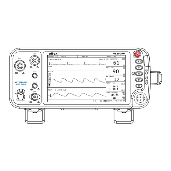
Chapter 3: Controls and Features Chapter 3: Controls and Features 3.1 Indicators and Displays with Embedded Submenus The monitor has a high-resolution, high-contrast, color LCD display. It provides a continuous, real-time display of up to four waveforms. It also shows measured values, chronological data, measurement trends, alarm limits and patient information. - Page 26 Chapter 3: Controls and Features performing monitoring functions. There are several points of entry into the monitor's menu system including the main menu, parameter menus, and waveform menus. Up to three waveform channels can be displayed Waveform simultaneously. Every channel can be assigned to a Channel waveform from any enabled parameter, graph, table or blank.
-
Page 27: Keys
Chapter 3: Controls and Features High and Low The high and low alarm limits for the alarm limits numeric measured values are displayed. If you do not set alarm limits for a new patient, the default high and low limits will be used. -
Page 28: Left Panel
Chapter 3: Controls and Features The rotary knob is a dial control with a push Rotary selection switch. It is located on the front of the Knob monitor, in the lower right corner. Turn the rotary knob to navigate the cursor around the display. Push the knob to select highlighted options. -
Page 29: Back Panel
Chapter 3: Controls and Features Connector (T1 the patient connector is attached to the monitor. A up and T2 low) measured value for temperature (TEMP) will be displayed when the sensor is attached to the patient. Non-Invasive Attach the NIBP cuff to the monitor. Measured values for Blood Pressure non-invasive blood pressure (systolic, diastolic, and mean) will be displayed when the most recent NIBP... -
Page 30: Internal Battery
Chapter 3: Controls and Features panel and on the bottom of the monitor. 3.5 Internal Battery The installed internal rechargeable battery is intended primarily for backup and switch-over use. Charge the battery after the monitor has operated using battery power or after the monitor has been shipped or stored. To charge the battery, connect the AC power cord to the monitor and to the AC power source. - Page 31 Chapter 3: Controls and Features battery is fully charged. Allow the battery to fully recharge before using the monitor under battery power. NOTE! When approximately 15 minutes of battery use remains, the red battery icon is displayed in the information bar and a high priority alarm will occur.
- Page 32 Chapter 3: Controls and Features This Page is Intentionally Left Blank! Veterinary Vital Signs Monitor Operation Manual...
-
Page 33: Chapter 4: Setting Up The Monitor
Chapter 4: Setting up the Monitor Chapter 4: Setting up the Monitor 4.1 Unpacking the Monitor and Check the Shipment 1. Carefully remove the monitor and its accessories from the shipping carton. Save the packing materials in case the monitor must be shipped or stored. -
Page 34: Basic Operation
Chapter 4: Setting up the Monitor 3. Plug the AC power cord into the power connector on the back of the monitor. 4. Plug the other end of the AC power cord into a grounded, three-wire hospital-grade outlet. 5. Verify that the front panel AC Power LED is lit. WARNING! Do not plug the monitor into an outlet controlled by a wall switch. -
Page 35: Systems Setup
Chapter 4: Setting up the Monitor 4.5 Systems Setup Press the menu key to pop up the main menu and turn the rotary knob on the monitor to move the cursor to the “System” option. Then press the rotary knob to enter its submenu. The setup window will be shown as below, Figure 4.2: System Setup 4.5.1 Time Setup If necessary, set the time and date on the display. -
Page 36: Unit Setup
Chapter 4: Setting up the Monitor 4.5.2 Unit Setup Units of measurement can be changed for TEMP and NIBP. The selected units of measurement will remain in the monitor's memory until changed, even if the monitor is turned off. Figure 4.3: Unit Setup 1. -
Page 37: Volume Setup
Chapter 4: Setting up the Monitor When connecting the monitor to a computer or a center monitor, you need to setup the IP address. Figure 4.4: Net Setup 1. Press the menu key to pop up the main menu and turn the rotary knob to move the cursor to the “System”... -
Page 38: Lcd Brightness Setup
Chapter 4: Setting up the Monitor 1. Press the menu key to pop up the main menu and turn the rotary knob to move the cursor to the “System” option. 2. Push the rotary knob to access the “System” submenu. Turn the knob to highlight the “Volume”... -
Page 39: Power Setup
Chapter 4: Setting up the Monitor 5. Turn the rotary knob to “OK” or “Cancel” button and push it to save or delete your settings. 4.5.7 Power Setup When the monitor is connected to an AC power source, the frequency should be set relatively. -
Page 40: Set Patient Information
Chapter 4: Setting up the Monitor Figure 4.8: Language Setup 1. Press the menu key to pop up the main menu and turn the rotary knob to move the cursor to the “System” option. 2. Push the rotary knob to access the “System” submenu. Turn the knob to highlight the “Language”... -
Page 41: Patient Setup
Chapter 4: Setting up the Monitor Press this key to exit the character board. Press it to change the character board into letters and switch between capital and lowercase letters. Press it to change the character board into numbers and punctuation. Delete button. -
Page 42: Display Setup
Chapter 4: Setting up the Monitor Enter the patient’s age, for example: 10 Patient Type Choose the patient’s type: DOG, CAT and HORSE. 3. Turn the rotary knob to “OK” or “Cancel” button and push it to save or delete your settings. 4.7 Display Setup Press the menu key to pop up the main menu and turn the rotary knob to move the cursor to the “Display”... -
Page 43: Customize Display Modes
Chapter 4: Setting up the Monitor c). Huge Digit Display Mode d). oxyCRG Display Mode 4.7.1 Customize Display Modes Besides the above four main display modes, user can also customize the display modes and save as user format modes. Figure 4.12: Custom Format 1. - Page 44 Chapter 4: Setting up the Monitor This Page is Intentionally Left Blank! 4-12 Veterinary Vital Signs Monitor Operation Manual...
-
Page 45: Chapter 5: Monitoring The Patient
Chapter 5: Monitoring the Patient Chapter 5: Monitoring the Patient Follow the steps in Chapter 4: Setting Up the Monitor; the remainder of this chapter assumes that the monitor is properly installed and set up. 5.1 General Monitoring Instructions Regardless of the parameters or measured values you want to monitor, follow these steps when you are ready to attach a patient. -
Page 46: Adjust The Parameter Box Settings
Chapter 5: Monitoring the Patient middle of the display. The settings available for selected waveform will be displayed. Refer the chapters dedicated to each parameter for more details regarding waveform settings. 5.4 Adjust the Parameter Box Settings 1. Turn the rotary knob on the monitor to move the cursor. Highlight the parameter box and push the knob to access the parameter menu in the middle of the display. -
Page 47: Use These Features As Needed
Chapter 5: Monitoring the Patient NOTE! Alarms may be tested while the monitor is in use by setting alarm limits such that the measured value is outside the limits. Return the alarm limits to their clinically appropriate settings after testing. To set the high and low alarm limits: 1. -
Page 48: Nibp Mode
Chapter 5: Monitoring the Patient NOTE! Only qualified personnel may silence the alarm temporarily, or enable it indefinite. 3. If the alarm limit is still violated after two minutes, the audible alarm tone will sound again. If, within the two minutes of alarm silence, another measured value matches or exceeds its alarm limits, the alarming action will resume, including the audible alarm tone. -
Page 49: Freeze Mode
Chapter 5: Monitoring the Patient 5.6.3 Freeze Mode Use this feature to temporarily hold or freeze all current waveforms, even those that are not displayed. Monitoring does not stop; you can still view the current measured values in the parameter boxes. When you freeze the waveforms, you may not adjust any waveform settings. -
Page 50: Viewing Stored Trend Data
Chapter 5: Monitoring the Patient 5.6.5 Viewing Stored Trend Data To view the stored trend data, press the menu key and turn the rotary knob on the monitor to move the cursor to “Review” option and push to access the review submenu shown as below. - Page 51 Chapter 5: Monitoring the Patient The information in the trend table is displayed as a list. The available number and categories of parameters are the same as with the trend graph. In the trend table, the median time is the cursor time value in the trend graph. The value of each parameter is date and time (except NIBP).
- Page 52 Chapter 5: Monitoring the Patient This page is intentionally left blank! Veterinary Vital Signs Monitor Operation Manual...
-
Page 53: Chapter 6: Alarms
Chapter 6: Alarms Chapter 6: Alarms 6.1 Parameter Alarms and Technical Alarms A parameter alarm occurs when a numeric measured value matches or exceeds the high or low limit set for that parameter. A technical alarm occurs when there is a malfunction with any of the sensors or connections, or when the battery is low or when an error is detected during self-test. -
Page 54: Controlling Alarms
Chapter 6: Alarms A low priority alarm sound consists of a single burst of one single tone that repeats every 20 seconds. The alarm message will be displayed in the alarm status bar with a yellow flashing background; the violating measured value will not flash. -
Page 55: Change Alarm Limits
Chapter 6: Alarms Figure 6.1: Alarm Setup To change alarm settings, 1. Press the menu key to pop up the main menu and turn the rotary knob to move the cursor to the “Alarm” option and push the knob to select. 2. -
Page 56: Silence Alarms
Chapter 6: Alarms WARNING! The alarm settings are set to factory defaults. Once reset according to patient conditions, current alarm settings are saved for up to 30 minutes after the monitor is turned off. If the monitor is not turned back on for 30 minutes, alarm limits are automatically reset to factory defaults. -
Page 57: Chapter 7: Ecg
Chapter 7: ECG Chapter 7: ECG 7.1 ECG Measurement Capability The Vital Signs Monitor provides continuous five-lead ECG processing with standard lead selections and filtering from electrocautery discharge. The heart rate measured value (HR) and primary lead messages are displayed in the HR parameter box, and a waveform for the primary ECG lead is continuously displayed. -
Page 58: Attaching The Patient
Chapter 7: ECG The monitor's ECG circuitry amplifies, filters, and digitizes (converts analog signals to digital signals) the received electrical potentials. The digitized signals are used to display the ECG waveform and calculate the ECG heart rate 7.4 Attaching the Patient NOTE! Follow institutional standards when applying ECG electrodes. - Page 59 ECG information and to protect against noise and other interference, use only ECG electrodes and cables specified by Utech. 3. Place the ECG leads to the patient. Be sure that the leads are in the correct ECG cable position. The ECG leads and patient cable connector are color-coded.
-
Page 60: Choosing The Waveform Settings
Chapter 7: ECG The monitor will automatically detect when the ECG cable is connected. Heart rate (HR) will be displayed in the HR parameter box and the primary ECG waveform will appear on the waveform channel. 7.5 Choosing the Waveform Settings Use the ECG waveform menu options to choose the primary ECG lead and adjust the settings for the size and speed of the ECG waveform. -
Page 61: Choose The Waveform Size
Chapter 7: ECG To change the primary lead: 1. On the ECG waveform menu, highlight LEAD and push the knob to access the ECG leads submenu. 2. Highlight the desired primary ECG lead and push the knob to select. See the following tables for the primary lead configuration. -
Page 62: Choose The Waveform Speed
Chapter 7: ECG 2. Highlight the desired size of the waveform (X1/4, X1/2, X1, X2, or X4) and push the knob to select. 3. Turn the rotary knob to “OK” or “Cancel” to save or delete your settings. 7.5.4 Choose the Waveform Speed You can choose the speed at which the ECG waveform is updated. - Page 63 Chapter 7: ECG Figure 7.6: HR Alarm Setup 1. Turn Alarm Detection On or Off You can turn on or off the alarm detection capability for the heart rate value. If HR ALARMS is on, an alarm will be issued when the high or low alarm limit is violated.
- Page 64 Chapter 7: ECG c) Choose Senior, Junior or Medium and push the knob to select. d) Turn the rotary knob to “OK” or “Cancel” to save or delete your settings. 7.6.2 Choose the Heart Rate Source The Vital Signs Monitor can measure the heart/pulse rate using two different parameters: ECG and oximetry (SpO ).
- Page 65 Chapter 7: ECG Figure7.8: Choose HR Source 1. Push and turn the rotary knob on the monitor to move the cursor. Highlight the HR parameter box and push the knob to access the HR parameter menu. 2. Highlight HR Source and push the knob to select. 3.
- Page 66 Chapter 7: ECG 1. Push and turn the rotary knob on the monitor to move the cursor. Highlight the HR parameter box and push the knob to access the HR parameter menu. 2. Highlight the ST switch and push the knob to select. 3.
- Page 67 Chapter 7: ECG a) Push and Turn the rotary knob on the monitor to move the cursor. Highlight the HR parameter box and push the knob to access the HR parameter menu. b) Highlight ST ALARM and push the knob to select. c) Choose the source of ST section from lead I, II, III, aVR, aVL, aVF, V.
- Page 68 Chapter 7: ECG This Page is intentionally left blank! 7-12 Veterinary Vital Signs Monitor Operation Manual...
-
Page 69: Chapter 8: Oximetry
Chapter 8: Oximetry Chapter 8: Oximetry 8.1 Oximetry Measurement Capability The oximetry parameter provides the continuous non-invasive monitoring of oxygen saturation (%SpO ) in the blood and peripheral pulse rate (PPR). The measured values for oximetry (%SpO and PPR) and a pulse strength bar graph are displayed in the SpO parameter box. - Page 70 Chapter 8: Oximetry WARNING! Use only SpO sensors supplied with, or specifically intended for use with, this device. WARNING! SpO measurements may be adversely affected in the presence of high ambient light. Shield the sensor area (with a surgical towel, for example) if necessary. WARNING! Dyes introduced into the bloodstream, such as methylene blue, indocyanine green, indigo carmine, patent blue (PBV), and fluorescein may adversely affect the accuracy of the SpO...
- Page 71 Chapter 8: Oximetry Figure 8.1: Theory of Operation 1. Low intensity Red and Infrared LED light sources 2. Detector Oximetry processes these signals, separating the time invariant parameters (tissue thickness, skin color, light intensity, and venous blood) from the time variant parameters (arterial volume and SpO ) to identify the pulses and calculate functional oxygen saturation.
- Page 72 Chapter 8: Oximetry every 4 hours. WARNING! When attaching sensors with Microfoam tape, do not stretch the tape or attach the tape too tightly. Tape applied too tightly may cause inaccurate readings and blisters on the patient's skin (lack of skin respiration, not heat, causes the blisters). 1.
- Page 73 Chapter 8: Oximetry •The monitor will automatically detect when the SpO2 patient cable is connected and the oximetry parameter will be active. 5. Attach the sensor to the patient. a) Make sure the red light in the sensor is illuminated. b) Select the appropriate sensor size.
-
Page 74: Access The Waveform Menu
Chapter 8: Oximetry directed in the sensor directions for use. High ambient light source such as surgical lights (especially those with a xenon light source), bilirubin lamps, fluorescent lights, infrared heating lamps, and direct sunlight can interfere with the performance of a SpO sensor. -
Page 75: Choose The Waveform Speed
Chapter 8: Oximetry Figure 8.2: Fill Pleth Waveform To fill the pleth or not: 1. On the pleth menu, highlight WAVEFROM and push the knob to select. 2. Highlight the desired option (On/ Off)and push the knob to select. 3. Turn the rotary knob to “OK” or “Cancel” to save or delete your settings. 8.6.3 Choose the Waveform Speed You can choose the speed at which the Pleth is displayed. -
Page 76: Adjusting The Settings In The Parameter Box
Chapter 8: Oximetry 3. Turn the rotary knob to “OK” or “Cancel” to save or delete your settings. NOTE! ! ! ! The ECG waveform speed will be changed corresponding with the pleth speed. 8.7 Adjusting the Settings in the Parameter Box 8.7.1 SpO Alarm Setup Figure 8.4: SpO... -
Page 77: Choose The Averaging Period For The Oximetry Parameter
Chapter 8: Oximetry a) Push and Turn the rotary knob on the monitor to move the cursor. Highlight the SpO parameter box and push the knob to access the SpO parameter menu. b) Highlight ALARM and push the knob to select. c) Move the cursor to High/Low and push the knob to select. - Page 78 Chapter 8: Oximetry Figure 8.5: Choose SpO Average Period To choose the averaging period: 1. Highlight AVRG. and push the knob to select. 2. Choose the desired averaging period (4 beats, 8 beats, 16 beats) and push the knob to select. AVERAGING PERIOD FOR %SPO2 AVERAGING PERIOD FOR PR READINGS...
-
Page 79: Chapter 9: Non-Invasive Blood Pressure
9.2 Non-invasive Blood Pressure Warnings, Cautions, and Notes WARNING! Blood pressure measurements may be inaccurate if cuffs and/or hoses other than those specified by Utech Co., Ltd. are used. WARNING! Verify cuff size is correct for the selected patient mode on the monitor. -
Page 80: Nibp Theory Of Operation
Mean arterial blood pressure measurements determined with this device are equivalent to those obtained by an intra-arterial blood pressure measurement device as determined by Utech Co., Ltd. 9.3 NIBP Theory of Operation The Vital Signs Monitor uses oscillometric principles to calculate the systolic, diastolic and mean arterial pressure values from the blood pressure cuff. -
Page 81: Measurement Limitations
1. Choose a blood pressure cuff appropriate for the patient and the limb size by measuring the circumference of the limb. See the table below. WARNING! Blood pressure measurements may be inaccurate if cuffs and/or hoses other than those specified by Utech Co., Ltd. are used. NOTE! The NIBP Cuff Kit is latex-free. - Page 82 Chapter 9: Non-invasive Blood Pressure CAUTION! Extremity and cuff motion should be minimized during blood pressure determinations. CAUTION! Proper blood pressure cuff size and placement are essential to the accuracy of the blood pressure determination. CAUTION! Any blood pressure recording can be affected by the position of the patient, his or her physiologic condition, and other factors.
- Page 83 Chapter 9: Non-invasive Blood Pressure ■ If there are doubts regarding the accuracy of the reading, check the patient’s vital signs using other means before checking the functions of the monitor. 3. Connect the NIBP supply hose to the monitor. WARNING! Make sure that hoses are not kinked, compressed, or restricted.
-
Page 84: Adjusting The Settings In The Parameter Box
Chapter 9: Non-invasive Blood Pressure 2. Turn the rotary knob to choose a test mode (AUTO, MANUAL, or STAT), and push the knob to select. •If you choose AUTO or STAT, the selected mode will be displayed in the parameter box. 9.6 Adjusting the Settings in the Parameter Box 9.6.1 NIBP Alarm Setup 1. -
Page 85: Choose The Interval For Automatic Nibp Measurements
Chapter 9: Non-invasive Blood Pressure d) Turn the rotary knob to “OK” or “Cancel” to save or delete your settings. 2. Set High and Low Alarm Limits The alarm limits displayed in the parameter box are the high and low alarm limits for SYS and DIA. -
Page 86: Assist Venous Puncture
Chapter 9: Non-invasive Blood Pressure according to the interval you select (2, 3, 5, 10, or 30 minutes, or 1, 2 hours). The time remaining until the next measurement will be displayed in the parameter box. Figure 9.5: Choose NIBP Interval To choose the automatic NIBP measurement interval: 1. -
Page 87: Measuring Non-Invasive Blood Pressure (Nibp)
Chapter 9: Non-invasive Blood Pressure 1. In the NIBP parameter menu select Venous Puncture. 2. Puncture vein and draw blood sample. 3. Reselect Venous Puncture to deflate the cuff. During measurement, the NBP display shows the inflation pressure of the cuff and the remaining time in venous puncture mode. -
Page 88: Canceling The An Nibp Measurement
Chapter 9: Non-invasive Blood Pressure If the measurement is successful, you will see the systolic, diastolic, and mean arterial pressure values displayed in the NIBP parameter box and you will hear the completion beep. The time of the successful reading will also be displayed in the parameter box. -
Page 89: Chapter 10: Respiration Rate (Resp)
Chapter 10: Respiration Rate Chapter 10: Respiration Rate (Resp) 10.1 Respiration Rate Measurement Capability The RESP parameter provides respiration rate (RPM) values. The measured value for RESP is displayed in the RR parameter box. For the respiratory measurement (Resp), the monitor measures the thoracic impedance between two ECG electrodes on the patient’s chest. -
Page 90: Choose The Waveform Size
Chapter 10: Respiration Rate You can choose one of the ECG lead as a source to measure the RR from lead I, II, III. The selected lead will be displayed in the waveform channel. Figure 10.1: Select ECG Lead To change the ECG lead: 1. -
Page 91: Choose The Waveform Speed
Chapter 10: Respiration Rate 1. On the RESP waveform menu, highlight Gain Mode and push the knob to select. 2. Highlight the desired size of the waveform (X1/2, X1, X2, or X4) and push the knob to select. 3. Turn the rotary knob to “OK” or “Cancel” to save or delete your settings. 10.4.3 Choose the Waveform Speed You can choose the speed at which the RESP waveform is updated. - Page 92 Chapter 10: Respiration Rate Figure 10.4: RR Alarm Setup 1. Turn Alarm Detection On or Off You can turn on or off the alarm detection capability for the Resp rate value. If RR ALARMS is on, an alarm will be issued when the high or low alarm limit is violated.
- Page 93 Chapter 10: Respiration Rate e) Turn the rotary knob to “OK” or “Cancel” to save or delete your settings. 3. Choose Alarm Priority a) Push and Turn the rotary knob on the monitor to move the cursor. Highlight the RR parameter box and push the knob to access the RR parameter menu. b) Highlight RR ALARM and push the knob to select.
- Page 94 Chapter 10: Respiration Rate This Page is Intentionally Left Blank! 10-6 Veterinary Vital Signs Monitor Operation Manual...
-
Page 95: Chapter 11: Temperature
Use only temperature sensors and interface cables specifically intended for use with this device. 11.3 Attaching the Patient 1. Choose a temperature sensor. Each temperature channel is compatible with Utech Co., Ltd. YSI 400-series disposable temperature sensors, or equivalent. Veterinary Vital Signs Monitor Operation Manual 11-1... -
Page 96: Adjusting The Settings In The Parameter Box
Chapter 11: Temperature 2. Apply the temperature sensor to the patient according to the standards of practice and care for your facility, and according to the temperature sensor manufacturer’s instructions. 3. If applicable, connect the temperature sensor to the interface cable. 4. - Page 97 Chapter 11: Temperature a) Push and Turn the rotary knob on the monitor to move the cursor. Highlight the TEMP parameter box and push the knob to access the TEMP parameter menu. b) Highlight ALARM and push the knob to select. c) Choose ON or OFF and push the knob to select.
- Page 98 Chapter 11: Temperature This Page is Intentionally Left Blank! 11-4 Veterinary Vital Signs Monitor Operation Manual...
-
Page 99: Chapter 12: Drug Calculator
Chapter 12: Drug Calculator Chapter 12: Drug Calculator Drug mixtures for intravenous (IV) drug infusions combine information on drug dose, rate, amount, volume, concentration, and standardized rate. The Drug Calculator helps you to manage infusions by calculating one of these values at a time. -
Page 100: Glossary
Chapter 12: Drug Calculator After the drug measurement unit is set, the drug weight and concentration units in the drug calculator adjust accordingly. Time units Min (minute) and hr (hour) are used as time units. After setting the time unit, the dosage rate and infusion rate units in the drug calculator adjust accordingly. -
Page 101: Performing Drug Calculation
Chapter 12: Drug Calculator dropped form the infusion device. The unit is GTT. Drip/ml: The number of drops (guttae) per unit volume (ml) dropped form the infusion device. The unit is GTT. 12.4 Performing Drug Calculation A list of drugs can be configured for the monitor containing predefined dosage recommendations and unit settings. - Page 102 Chapter 12: Drug Calculator The user can enter at least three known items according to the calculation requirements. The drug calculator will automatically calculate using the default equations. All fields are initially displayed as 0.00 and can be filled with value. After the user inputs the known item, the drug calculator will begin calculating and the result will be displayed in real time.
-
Page 103: Charting Infusion Progress
Chapter 12: Drug Calculator Amrinone Lactate 1~3mg/ml 5~10ug/kg/min 5 ~10mg/kg Bretylium Tosilate 10mg/ml 1~50mg/min 5~10mg Dobutamine 0.5~5mg/ml 2.5~40ug/kg/min 250mg Dopamine <3.2mg/ml 1~30ug/kg/min 10~20mg Epinephrine <64ug/ml 1~4ug/min 0.025~1mg Heparin Sodium 20~40U/ml 15~20U/kg/h±10% 6000~20000U Isuprel 2~4ug/ml 2~20ug/min 0.5~1mg Lidocaine <8mg/ml 1~4mg/min 1~2mg/kg Morphine 0.5~5mg/ml <2mg/min... -
Page 104: Using The Titration Table
Chapter 12: Drug Calculator Press “OK” to exit the table and return to the drug calculator main widow. 12.6 Using the Titration Table Use the Titration Table to see at a glance what dose your patient would receive of a drug at different infusion rates. The higher the infusion rate entered, the bigger the steps between table entries. -
Page 105: Chapter 13: Maintenance And Troubleshooting
The Vital Signs Monitor Service Manual also contains the circuit diagrams, parts lists, and descriptions required for carrying out repairs and disposing of batteries. The Service Manual is available on request from Utech Co., Ltd. or your local agent. MAINTENANCE ITEM... -
Page 106: Long-Term Storage
Chapter 13: Maintenance and Troubleshooting WARNING! Do not autoclave, ethylene oxide sterilize, or immerse the monitor in liquid. CAUTION! Do not allow water or any other liquid to be spilled onto the monitor. Unplug the AC power cord from the monitor before cleaning or disinfecting. - Page 107 Chapter 13: Maintenance and Troubleshooting monitor is not lit. The AC power cord is Only connect the AC power connected to a wall outlet cord to an outlet that is not that is controlled by a controlled by a wall switch. wall switch.
-
Page 108: Maintenance Menu
Chapter 13: Maintenance and Troubleshooting The SpO sensor is Reposition the sensor on the improperly positioned on patient. the patient. Reposition the sensor on the The patient is patient. experiencing poor perfusion. Either the SpO sensor or Change the sensor or contact the manufacturer service the extension cable is department. -
Page 109: Back To Factory Default Values
Chapter 13: Maintenance and Troubleshooting 13.4.2 Back to Factory Default Values You can set up your monitor to operate using the default values you choose for alarm limits, volume, LCD brightness, parameter settings. Figure 13.1: Factory Default Values 1. Press the menu key to pop up the main menu and turn the rotary knob to move the cursor to the “Maintenance”... - Page 110 Chapter 13: Maintenance and Troubleshooting Figure 13.2: Demo Mode To turn on the demo mode: 1. On the maintenance menu, highlight DEMO and push the knob to select. 2. Turn the rotary knob to highlight OFF and push the knob to select. 3.
-
Page 111: Chapter 14: Optional Supplies And Accessories
3967 Each Rectal Temperature Probe 3968 14.1 Ordering Information For ordering information, contact your local distributor or the Utech Co., Ltd. customer service department at the address or phone number below: floor, NO.39, Jinqiao Road, Zhangjiawan, Shapingba District, Chongqing, China... - Page 112 Chapter 14: Optional Supplies and Accessories This Page is Intentionally Left Blank! 14-2 Veterinary Vital Signs Monitor Operation Manual...
-
Page 113: Chapter 15: Specification
Chapter 15: Specification Chapter 15: Specification 15.1 Display 7-inch diagonal high-resolution TFT (Thin Film Transistor) Active Matrix LCD Resolution: 800 X 480 pixels 15.2 Indicators LEDs: Work Status LED AC Power LED Battery Charge LED Battery Supply LED Alarm Silence LED 15.3 Alarm Volume 45dBA to 85 dBA at 1 meter distance (adjustable) 15.4 Keys/User Controls... -
Page 114: Ecg
Chapter 15: Specification 15.4 ECG 20-350 bpm Heart Rate Range: ±2 bpm or ±2% (whichever is greater) Heart Rate Accuracy: 0.5 to 5 mV QRS Detection Range: ±2 mV to ±700 mV amplitude Pace Pulse Detection: 0.1 - 2.0 ms Detection Duration: High: 20-350 bpm and OFF Alarm Ranges Heart Rate:... -
Page 115: Nibp
Chapter 15: Specification 15.6 NIBP Blood Pressure Measuring Oscillometric with step-down deflation Method of Measurement: 40 to 270 mmHg Range: Systolic: Mean Arterial: 30 to 220 mmHg 20 to 200 mmHg Diastolic: Pulse: 25 to 300 bpm Algorithm based on human algorithm NIBP Accuracy: that meets or exceeds accuracy requirements of ANSI / AAMI SP10:1992... -
Page 116: Temperature (Temp)
Chapter 15: Specification 15.8 Temperature (TEMP) Channel: Range: 25-45 Accuracy: ± 0.2 C plus the temperature sensor tolerance Resolution: TEMP Alarm Range: High: 35.5-43.5 C and OFF in 0.1 Increments Low: 35.5-43.5 C and OFF in 0.1 Increments 15.9 Default Alarms Limits Default values of Default values of Parameter (unit) -
Page 117: Environmental
Chapter 15: Specification 15.12 Environmental C (Operating) 0 to 50 Temperature: -40 to 75 C (Storage) 15 to 95% (Operation) Humidity: 10 to 95% (Storage) 15.13 Equipment Classification Class 1 &Internally Powered Type of Protection: (Against Electric shock) Continuous Mode of operation: IPX1, drip proof Degree of Protection: (Against ingress of Liquids) - Page 118 Chapter 15: Specification This Page is Intentionally Left Blank! 15-6 Veterinary Vital Signs Monitor Operation Manual...
- Page 119 floor, NO.39, Jinqiao Road, Zhangjiawan, Shapingba District, Chongqing, China Phone (+86)23-6172-8390 (+86)23-6172-8391 E-mail service@chinautech.com Web site www.chinautech.com...
Need help?
Do you have a question about the VS2000V and is the answer not in the manual?
Questions and answers