Table of Contents
Advertisement
Advertisement
Table of Contents

Related Manuals for BC Group International BC Biomedical ULT-2020 Series

Summary of Contents for BC Group International BC Biomedical ULT-2020 Series
- Page 1 ULTRASOUND TRANSDUCER LEAKAGE TESTER ULT-2000 SERIES USER MANUAL...
-
Page 3: Table Of Contents
BC BIOMEDICAL ULT-2000 SERIES TABLE OF CONTENTS WARNINGS, CAUTIONS, NOTICES ................ii DESCRIPTION ....................... 1 BACKGROUND ......................4 TEST PROCESS......................8 LAYOUT ......................... 9 KEYS ..........................10 SCREENS ........................11 SETUP .......................... 18 PC SOFTWARE ......................21 COMMUNICATION PROTOCOL .................. 22 MANUAL REVISIONS .................... - Page 4 To ensure the accuracy of the ULT-2000 Series, BC Group International, Inc. recommends calibration at least once every 12 months. Calibration must be done by qualified personnel. Contact BC Group International, Inc. for calibration. PREVENTIVE MAINTENANCE To ensure the proper operation of the ULT-PA-XX Series, and ULT-PC-XX Series, BC Group International, Inc.
- Page 5 WARNING - CONNECTIONS All connections to patients must be removed before connecting the DUT to the ULT-2000. A serious hazard may occur if the patient is connected when testing with the ULT-2000. Do not connect any leads from the patient directly to the ULT-2000 or DUT.
- Page 6 CAUTION - SERVICE The ULT-2000 is intended to be serviced only by authorized service personnel. Troubleshooting and service procedures should only be performed by qualified technical personnel. CAUTION - ENVIRONMENT Exposure to environmental conditions outside the specifications can adversely affect the performance of the ULT-2000.
- Page 8 NOTICE – SYMBOLS Symbol Description Caution (Consult Manual for Further Information) Electrical Caution (Consult Manual for Further Information) Center Negative (Refers to Battery Eliminator Connector) Per European Council Directive 2002/95/EC, do not dispose of this product as unsorted municipal waste. NOTICE –...
- Page 9 APPLICATION OF EQUIPMENT OUTSIDE OF THE PUBLISHED INTENDED USE AND SPECIFICATIONS. NOTICE – DISCLAIMER BC GROUP INTERNATIONAL, INC. RESERVES THE RIGHT TO MAKE CHANGES TO ITS PRODUCTS OR SPECIFICATIONS AT ANY TIME, WITHOUT NOTICE, IN ORDER TO IMPROVE THE DESIGN OR PERFORMANCE AND TO SUPPLY THE BEST POSSIBLE PRODUCT.
-
Page 10: Description
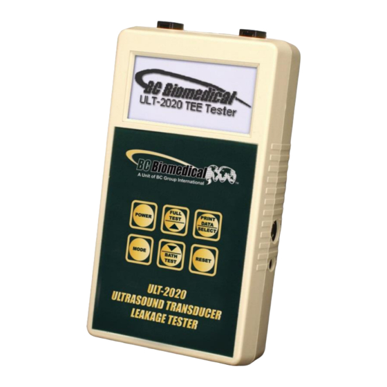
BC BIOMEDICAL ULT-2000 SERIES ULTRASOUND TRANSDUCER LEAKAGE TESTER The Model ULT-2000 Series is a family of Microprocessor based, Ultrasound Transducer Leakage Testers. The ULT-2010 measures both the conductivity of the cleaning medium and the leakage current of the ultrasound transducer. The ULT-2020 offers the same features of the ULT-2010, plus a Meter mode and Data Logging. - Page 11 ULT-2020 (METER, DATALOG) HAS ALL THE BASIC MODEL FEATURES PLUS: • METER MODE FOR EXTENDED MEASUREMENT PERIODS • PROGRAMMABLE METER SOURCE (CHALLENGE) VOLTAGE AND FREQUENCY • PROGRAMMABLE METER TIMER • DATALOG WITH STORAGE OF 99 TEST RECORDS STANDARD ACCESSORIES: BC20-21111 UNIVERSAL BATTERY ELIMINATOR BC20-41357 PC SOFTWARE (LIMIT CONFIGURATION TOOL)
- Page 12 CONDUCTIVITY PROBES: (not included, order separately) ULT-PC-10 DUAL CONDUCTIVITY PROBE (Short) ULT-PC-15 DUAL CONDUCTIVITY PROBE (Medium) ULT-PC-20 DUAL CONDUCTIVITY PROBE (Short & Long) ULT-PC-25 FOR USE WITH GUS CLEANING SYSTEM ULT-PC-30 DUAL CONDUCTIVITY PROBE (Flexible) ULTRASOUND TRANSDUCER ADAPTERS: (not included, order separately) TRANSDUCER ADAPTER MODEL...
-
Page 13: Background
BACKGROUND The following is the minimal equipment needed to test the electrical safety of ultrasound transducers: 1) ULT-2000 Series Ultrasound Transducer Electrical Leakage Tester 2) Dual Conductivity Probe (See list on page 3) 3) Ultrasound Transducer Adapter (See list on page 3) 4) Test Basin (BC20-42200) The ULT-2000 is designed to test the electrical safety of all types of diagnostic ultrasound transducers, independent of the ultrasound machines on which they are typically used. - Page 14 for the actual ultrasound machines. The ULT-2000 is the only battery-operated handheld tester on the market today that tests according to these established protocols, which have been adopted by diagnostic ultrasound manufacturers. It tests both the upper and lower limit thresholds for electrical leakage currents. Typical electrical safety (leakage) testing of the diagnostic ultrasound transducer should occur as part of the routine cleaning and disinfecting activity that is performed between patient ultrasound procedures.
- Page 15 During testing, the transducer is subjected to a user selectable source voltage. This voltage is typically set to the normal operating voltage of the transducer’s ultrasound machine. In North America, the source voltage is typically set to 120 VAC @ 60 Hz. For countries where the normal operating voltage is 230 VAC, the source voltage can be set to this level, at either 50 or 60 Hz, as appropriate.
- Page 16 NOTICE – TESTING CONDUCTIVE SURFACES SUCH AS METAL CARTS OR TABLETOPS CAN CAUSE ERRONEOUS READINGS DUE TO ALTERNATE LEAKAGE PATHS FROM TRANSDUCER ADAPTERS, CABLES, ETC. ENSURE TEST IS DONE ON A NON- CONDUCTIVE SURFACE FOR BEST RESULTS.
-
Page 17: Test Process
TEST PROCESS The ULT-2000 series completes four intermediate tests as part of the Full Test to fully evaluate the integrity of an ultrasound probe. The following is the details of each test step: Source Voltage Test - The first step is to read the actual source (challenge) voltage that will be applied during the testing to ensure that it is within range. -
Page 18: Layout
LAYOUT This section looks at the physical layout of the ULT-2000 Series and gives descriptions of the elements. The Locking DUT Connections are Interchangeable Locking DUT Connector Locking DUT Connector – To conductive bath via Dual Conductivity Probe – To conductive bath via –... -
Page 19: Keys
KEYS Six tactile-touch keys with audio feedback are provided for system operation: – This key turns the unit on and off. The unit will initiate with the Main Screen. – At the Main Screen, this key initiates the Full Test, which includes a Source Voltage Test, a Self Test, a Bath Test, and a transducer Probe Test. -
Page 20: Screens
SCREENS MAIN SCREEN – The main screen indicates that the ULT-2000 Series unit is initialized and ready for testing. This screen displays after power-up initialization, and can be accessed by pressing the key at any time other than during setup mode. FULL TEST SCREEN –... - Page 21 BATH TEST SCREEN – This screen is accessed from the Main Screen by pressing the button. It displays Bath Test information, measurements, and progress. Bath Test Process: DUT Information Manufacturer: Model SOURCE VOLTAGE TEST - verifies the voltage circuit to be used during testing.
- Page 22 METER MODE SCREEN (ULT-2020 ONLY) – The meter mode screen allows extended leakage current measurements, which can be useful when troubleshooting ultrasound transducer probes and cables. This screen displays the current leakage current reading and user selectable Source Voltage, Source Frequency, and Output Control. This screen is accessed from the Main Screen by pressing the key.
- Page 23 DATALOG SCREEN (ULT-2020 ONLY) – The Datalog Screen displays the test results of up to 99 test records. The Datalog Screen includes a Record Number, Date / Time Stamp, Probe Information, Test Results, Test Measurements, and Test Limits. This screen is accessed from the Meter Screen by pressing the key.
- Page 24 Use the key to print the displayed record to the serial printer. Below is a sample print.
- Page 25 DEVICE CONFIGURATION SCREEN – The Device Configuration displays the current test configuration. Device Configuration parameters include Test Limit Mode, Probe Manufacturer, and Probe Model. This screen is accessed from the Datalog Screen by pressing the key. The parameters are selected by pressing the key until the desired parameter is highlighted.
- Page 26 LOW BATTERY – When the battery life is 10% or less, the LOW BATTERY message box appears and indicates the remaining battery life. BATTERY ELIMINATOR INPUT – A 2.1 mm receptacle is provided for the 10 VDC Battery Eliminator (BC20-21111) that may be used for continuous run applications. It bypasses the internal battery when plugged in.
-
Page 27: Setup
SETUP Two user selectable setup menus are provided, SYSTEM CONFIGURATION and USER TEST CONFIGURATION. Enter a setup menu by pressing and holding the until the Access Code Screen appears (5 sec). The arrows are then used to enter the access code. DEFAULT ACCESS CODES SYSTEM CONFIGURATION = 1 USER TEST CONFIGURATION = 2... - Page 28 System Configuration Parameter Description Options Determines whether the test measurements (actual PASS / FAIL or test readings) are shown in the test screen, or if the Test Mode unit will simply give a PASS or FAIL result. The Numerical Default setting is Numerical. Determines the settings for the test limits.
- Page 29 USER TEST CONFIGURATION Below is the typical User Test Configuration Screen, followed by a table of the available parameters and a brief description of each option. User Test Configuration Parameter Description Range The Source Voltage applied during a test when Test Voltage 90-275 VAC Device Configuration is set to User Test Limits.
-
Page 30: Pc Software
PC SOFTWARE The included PC Software allows the user to create custom limit configurations including Manufacturer, Model, Leakage Limits, Test Voltage, and Frequency. Install and launch the PC Software, then connect the PC and ULT-2000 via cable BC20-41361 (See OPTIONAL ACCESSORIES at the beginning of this manual). Once connected, the software allows the user to download/read custom configurations to/from the ULT-2000. -
Page 31: Communication Protocol
COMMUNICATION PROTOCOL The communication protocol provides a means to completely configure and use the ULT- 2000 from a PC, allowing hands free or automated operation. Communication Port The Serial port is configured as 115,200 Baud Rate, 8 Data Bits, 1 Stop Bit, and No Parity. Command Syntax The command description is broken into columns;... - Page 32 ULT-2000 Communication Command Summary Subnodes Keywords Nodes Values OUTput VOLTage 90-275 FREQuency 50 hz, 60 hz TEST MODE NUMerical, PASSfail LIMits FIXed, DEFaults, CUSTom DMANufacturer 1-12 (Selects Manufacturer 1-12) DMODel 1-10 (Selects Model 1-10) CONFigure LIMits CONDuctivity 0 - 500 (uA) ULEAkage 0 - 500 (uA) LLEAkage...
- Page 33 ULT-2000 Communication Command Summary (cont.) Keywords Nodes Values Value Definition Test Running Bath Only Test Full Test Test Failed Test Passed STATus? 1024 2048 Program Mode 4096 Meter Mode 8192 14 16384 15 32768 Calibration Mode VTOLerance 0-25 % FVOLtage 90 - 275 VAC FCONductivity 0 - 500 uA...
-
Page 34: Manual Revisions
MANUAL REVISIONS Revision # Program # Revisions Made Rev 01 DT7331CA Origination Rev 02 DT7331CA Misc. Edits Rev 03 DT7331CA Adapter Information Updated Rev 04 DT7331CB Model Information Updated Rev 05 DT7331CC Dynamic Device Configuration Screen Rev 06 DT7331CC Edits to Euro Transformer, Conductivity Probe and Transducer Adapter List Updated, and Misc. -
Page 35: Limited Warranty
IMPLIED, INCLUDING, BUT NOT LIMITED TO ANY IMPLIED WARRANTY OF MERCHANTABILITY OR FITNESS FOR A PARTICULAR PURPOSE. BC GROUP INTERNATIONAL, INC. IS NOT LIABLE FOR ANY INCIDENTAL OR CONSEQUENTIAL DAMAGES. NO PERSON OTHER THAN AN OFFICER IS AUTHORIZED TO GIVE ANY OTHER WARRANTY OR ASSUME ANY LIABILITY. -
Page 36: Specifications
SPECIFICATIONS SOURCE, LEAKAGE AND CONDUCTIVITY SOURCE 90 - 275 VAC, ± 1% FS (CHALLENGE) 500 µA Max Load VOLTAGE SOURCE (CHALLENGE) 50 or 60 Hz, ± 0.5 Hz FREQUENCY 0.50 - 10.00 µA, ± 0.5 µA LEAKAGE 10.0 - 250.0 µA, ± 1% Range CURRENT 250.0 - 500 µA, ±... - Page 37 ELECTRICAL & MISC. 9V Lithium Battery BATTERY (ANSI/NEDA 1604LC or equivalent) 10 VDC, 300mA BATTERY ELIMINATOR BC20-21111 (Universal) > 100 Full Tests CONTINUOUS (Note: Backlight set to OFF) BATTERY LIFE 1 year BAUD 115200 DATA BITS START BITS STOP BITS PARITY none HANDSHAKING...
-
Page 38: Notes
NOTES... - Page 39 NOTES...
- Page 40 BC GROUP INTERNATIONAL, INC. 3081 ELM POINT INDUSTRIAL DRIVE ST. CHARLES, MO 63301 1-800-242-8428 1-314-638-3800 www.bcgroupintl.com sales@bcgroupintl.com ULT-2000 Series User Manual 05/20 – Rev 20 LM-7331X-UM Copyright © 2020 Made in the USA...
Need help?
Do you have a question about the BC Biomedical ULT-2020 Series and is the answer not in the manual?
Questions and answers