Table of Contents
Advertisement
Quick Links
FCC STATEMENT
1.
This device complies with Part 15 of the FCC Rules.
Operation is subject to the following two conditions:
(1)This device may not cause harmful interference, and
(2)This device must accept any interference received, including interference
that may cause undesired operation.
2. Changes or modifications not expressly approved by the party responsible for
compliance could void the user's authority to operate the equipment.
AEI PROTECT-ON SYSTEMS LIMITED
www.apo-hk.com
FOR DK-2800 SECURITY KEYPADS
VERSION: 10/2010
SPLIT-DECODED CONTROLLER
RoHS
Compliance
DA-2800 & DA-2801
Installation & Operation Manual
FOR ELECTRIC LOCK, INTER-LOCK
AND SECURITY SYSTEM INSTALLATIONS
Advertisement
Table of Contents

Related Manuals for Velleman DK-2800


Summary of Contents for Velleman DK-2800
- Page 1 SPLIT-DECODED CONTROLLER FCC STATEMENT FOR DK-2800 SECURITY KEYPADS This device complies with Part 15 of the FCC Rules. Operation is subject to the following two conditions: (1)This device may not cause harmful interference, and (2)This device must accept any interference received, including interference RoHS that may cause undesired operation.
-
Page 2: Table Of Contents
FUNCTION MODE / TIME: Mode = 0, TABLE OF CONTENTS Door Forced Open Warning 0---OFF Door Forced FUNCTION / TIME & Time Open 1-999 Seconds ..................4 INTRODUCTION Warning OFF Mode = 0,... - Page 3 ................. . . 3 4 THE PROGRAMMING SUMMARY CHART --- (Supplementary Information) User PIN Entry Mode .
-
Page 4: Introduction
Operation after programming. The DA-2800 or DA-2801 is a self-contained access controller. It has been designed mainly as the decoder unit working together with the keypads in the DK-2800 series to make up a split-decoded keypad system. button is equivalent to the button in the keypad with bell button. -
Page 5: Specifications
EXAMPLES: SPECIFICATIONS Example 1: Set Egress Button in Momentary contact 5 seconds with delay & warning beep Operating Voltage: 12V-24V DC, Auto Adjusting (a) Egress function programming, (b) Momentary contact with warning, (c) Delay time of 5 seconds to release door, Operating Current: (d) Entry confirmation 65mA (quiescent) to 100mA (three relays active) -
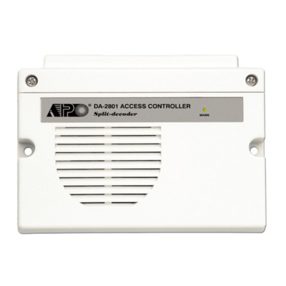
Page 6: The Split-Decoded Controller Unit (Figure 1)
EGRESS DELAY , WARNING AND ALARM (Location 90) THE SPLIT-DECODED CONTROLLER UNIT (Figure 1) LOCATION FUNCTION MODES DELAY TIME VALIDATION LINK-UP JUMPER CONNECTION MASTER OFF-->ON-->OFF TERMINALS CONFIGURATIONS OF THE EGRESS WARNING AND ALARM Key in the number to enable 1 of the 6 configurations described below: CODE LEARNING BUTTON --- Momentary Contact Mode without Warning -- (Default) -
Page 7: Installation
It is an unique solution to immediately up-grade a general purpose keypad to a high security access control system. All the keypads in the DK-2800 series with Data I/O Port are compatible with the Hospital: decoder. -
Page 8: The Necessary Connections For Split-Decoded
THE NECESSARY CONNECTIONS FOR SPLIT-DECODED STATUS LED FLASHING ON-OFF DURING STANDBY (Location 73) 1) Connect the Data I/O ports of the Decoder (Terminal 4) and the Keypad with wire to link-up the communication of LOCATION FUNCTION MODES VALIDATION the two units. INDIVIDUAL 2) Connect the Keypad PWR terminal of the Decoder (Terminal 3) to the keypad power input terminal, which supplies power to the keypad unit with current limit protection. -
Page 9: The Function Mode Jumper -- (Available On Da-2800 Only)
Example – Change of the Link-up Code ( The Master Code of the Master Keypad) USER PIN ENTRY MODE – Auto or Manual (Location 70) a) Put the Link-up Jumper of the Decoder from OFF to ON LOCATION ENTRY MODES VALIDATION INDIVIDUAL b) Set the Master Keypad to Programming Mode... -
Page 10: Connection Terminals
CONNECTION TERMINALS CONFIGURATION OF THE OUTPUT MODES OF OUTPUT 1, 2 AND 3 (Locations 51, 52 & 53) The three relay outputs of this keypad are programmable for Start/Stop or Timing modes. Apart from the door access control, alarm arm-disarm control, they are also universal timers for automatic operators in industry with their 99,999 seconds (over 24 hours) programmable timer. - Page 11 41 0999 # Leave this terminal open if the controller is in Stand Alone operation. (Stand Alone operation is one of the operation modes of the DK-2800) (a) Group Location , (b) The Group Deletion Command, (c) Confirmation, all Duress Codes in Location 5 : EG IN -- ( Egress Input) are cleared.
- Page 12 10 : DOOR SENS N.C. -- (Door Position Sensing Input -- Normally Close) Example 3: Delete a “Visitor Code” from Vistor ID in the memory A Normally Closed (N.C.) sensing point referring to (-) ground, with the help of a normally closed magnetic contact 40 02 # monitors the open or close state of the door.
- Page 13 Operation : (while the system is in the operation mode) 19 - 20 - 21 : OUTPUT 3 -- (Output Relay 3) 1 Amp relay dry contact controlled by the Group 3 User PINs & Cards in Split-decoded mode or by the RF remote Read Card Duress Code key in Stand Alone mode.
-
Page 14: The Audible & Visible Signals
THE AUDIBLE AND VISIBLE SIGNALS 4) Example 4 -- EM Card + Common User PIN : i) Programming : STATUS AUDIBLE SIGNALS MAINS LED SIGNALS 10 4 003 Read Card 1) Power-up Delay (5 Seconds) Continuous Beeps Continuous Fast Flashes 2) Power-up Delay (1 Minute)* Continuous Beeps Continuous Fast Flashes... -
Page 15: Rf Remote Controller -- (Da-2800 Only)
RF REMOTE CONTROLLER -- (DA-2800 ONLY) EXAMPLES – PROGRAMMING AND OPERATION The DA-2800 RF Remote Controller consists of a built-in receiver and two remote control keys, which has 4 channels 1) Example 1 -- EM Card Only : to control the Output Relay 1, 2, 3 and the built-in door chime. Two remote keys are supplied and up to 40 remote i) Programming : keys can be accommodated by the system. -
Page 16: Application Examples
Cards (Operation Media # 1, 3, & 4) and Private User PINs (Operation Media 2) MUST be unique. A repeated EM • Make 3-wire Connection (+, -, DATA I/O) to the keypad in the DK-2800 series. More than one keypads can be card or Private User PIN will be rejected and one long beep will be generated by the system to notify the owner. - Page 17 2) BASIC WIRINGS OF AN INTER-LOCK SYSTEM USING TWO SPLIT-DECODED KEYPADS OPERATION AND FUNCTIONS OF THE SUPER USER PIN 1) Operate Output 1, 2, and 3 The operation of the Super User PIN is just like a normal User PIN. Simply key-in the PIN with a specific output - ALARM O/P number for the desired Output.
-
Page 18: Application Hints For The Auxiliary Terminals
Example: APPLICATION HINTS FOR THE AUXILIARY TERMINALS User Name Location Function Code User ID PIN/Code Card # Remark (A) TAMPER N.C. The tamper switch is Normally Closed while the keypad TAMPER SWITCH is secured on the gang box. It is open when the keypad OF THE KEYPAD is removed from the gang box. - Page 19 FEATURE PROGRAMMING -- KEY IN AND STORE THE DESIRED VALUES (D) KEY ACTIVE OUTPUT The feature values can be set and stored into the system one by one with the desired Programming Locations. Programming can be made continuously and it is not necessary to be in sequence order. Just go to the desired ALARM ALARM programming location and key in the value for the desired feature.
-
Page 20: Refresh The System With The "Refreshing Code
REFRESH THE SYSTEM WITH THE “REFRESHING CODE” --- 9 9 9 9 (F) OUTPUT 2 OR OUTPUT 3 The system can be refreshed to clear all the old data stored and back to its ex-factory default values. ( i ) Shunting an N.C. Zone IMPORTANT NOTE: Make sure that you really want to clear ALL the OLD data before entering of the Refreshing Code. - Page 21 DIRECT ACCESS TO PROGRAMMING MODE WITH THE “DAP” CODE – 8 0 8 0 PROGRAMMING FOR FULL FEATURES --- (Supplementary Information) In the Split-decoded operation mode, the keypad becomes a data entry tool of the system and its Data I/O port always Set System Into Programming Mode With DAP Code In Case Of The Master Code Is Forgotten ! ! gives full feature data to the decoder.
Need help?
Do you have a question about the DK-2800 and is the answer not in the manual?
Questions and answers