Table of Contents
Advertisement
Quick Links
ML Maximum Power Point Tracking (MPPT) Series
ML2420N10-ML2430N10-ML2440N10-ML2430N12
Solar Charge and Discharge Controller
User Manual
ML2440N10
ML2430N10
ML2430N12
Model
ML2420N10
Battery voltage
12V/24V
Charging current
20A
30A
40A
30A
Discharging current
20A
Version: 1.02
Material Code
:1.1.24.01578
The above information is subject to change without prior notice.
Advertisement
Table of Contents

Related Manuals for Srne ML2440N10


Summary of Contents for Srne ML2440N10
- Page 1 ML Maximum Power Point Tracking (MPPT) Series ML2420N10-ML2430N10-ML2440N10-ML2430N12 Solar Charge and Discharge Controller User Manual ML2440N10 ML2430N10 ML2430N12 Model ML2420N10 Battery voltage 12V/24V Charging current Discharging current Version: 1.02 Material Code :1.1.24.01578 The above information is subject to change without prior notice.
-
Page 2: Table Of Contents
Table of Contents Dear users, Thank you for choosing our product ! 1. Product Introduction 1.1 Product Overview 1.2 Product Features 1.3 Exterior and Interfaces Safety Instructions 1.4 Introduction to Maximum Power Point Tracking Technology 1.5 Charging Stages Introduction 1. As this controller deals with voltages that exceed the top limit for human 2. -
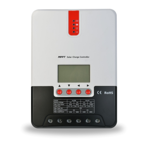
Page 3: Product Introduction
1. Product Introduction 1.3 Exterior and Interfaces 1.1 Product Overview ① RS232 ② • This product can keep monitoring the solar panel's generating power and tracking the highest voltage and current ③ values (VI) in real time, enabling the system to charge the battery in maximum power. It's designed to be used in off- ④... -
Page 4: Charging Stages Introduction
Compared with conventional PWM controllers, the MPPT controller can make the most of the solar panel's max. power 1.5 Charging Stages Introduction and therefore provide larger charging current. Generally speaking, the latter can raise the energy utilization ratio by 15% to 20% in contrast with the former. As one of the charging stages, MPPT can not be used alone, but has to be used together with boost charging, floating charging, equalizing charging, etc. -
Page 5: Product Installation
2) If no calibration has been done to the controller clock, the controller will perform equalizing charging regularly ML2420N10 according to its internal clock. ML2430N10 5 mm ML2440N10 10 mm >Floating charging When finishing the sustaining charging stage, the controller will switch to floating charging in which the controller ML2430N12 lowers the battery voltage by diminishing the charging current and keeps the battery voltage at the set value of floating charging voltage. - Page 6 ① Connecting to external temperature sampling interface Step 1: choose the installation site ② Connecting communication cable Do not install the controller at a place that is subject to direct sunlight, high temperature or water intrusion, ③ Connecting power cable and make sure the ambient environment is well ventilated.
-
Page 7: Product Operation And Display
ERROR indicator: Abnormality indication 3. Product Operation and Display Indicator state System operating normally 3.1 LED Indicators Steady on System malfunctioning PV array indicator Indicating the controller's current charging mode. Indicating the battery's current state. BAT indicator 3.2 Key Operations Indicating the loads' On/ Off and state. -
Page 8: Load Mode Setting Interface
3.3.1 Startup interface Mode Descriptions When no sunlight is present, the solar panel voltage is lower than the light control on voltage, and after a time delay, the controller will switch on the Sole light control load; when sunlight emerges, the solar panel voltage will become higher (nighttime on and daytime off) than the light control off voltage, and after a time delay, the controller will switch off the load. -
Page 9: Product Protection Function And System Maintenance
When the controller temperature exceeds the set value, it will decrease the charging power or halt charging. After entering into the setting interface, tap the Set key to switch the menu for setting, and tap the Up or Down key See the following diagram: to increase or decrease the parameter value in the menu. -
Page 10: Product Specification Parameters
User (self-customized) Battery type battery battery battery Value Parameter Over-voltage cut-off 16.0V 16.0V 16.0V —— 9~17V voltage ML2420 N10 ML2430N10 ML2440N10 ML2430N12 Model 14.6V —— 14.8V —— 9~17V Equalizing voltage 12V/24VAuto System voltage 14.4V 14.2V 14.6V 14.4V 9~17V Boost voltage No-load loss 0.7 W to 1.2W... -
Page 11: Conversion Efficiency Curve
6. Conversion Efficiency Curve 7. Product Dimensions 6.1 12V System Conversion Efficiency MPPT 12V conversion efficiency (12V battery) Φ Φ 4X 4 4X 10 ML2430N10/ML2440N10 Output power(W) Product dimensions:238*173*72.5mm 6X 8 Φ Hole positions:180*147mm Hole diameter:Φ3mm Applicable wire: max. 8 AWG 6.1 24V System Conversion Efficiency...
Need help?
Do you have a question about the ML2440N10 and is the answer not in the manual?
Questions and answers