Table of Contents
Advertisement
Quick Links
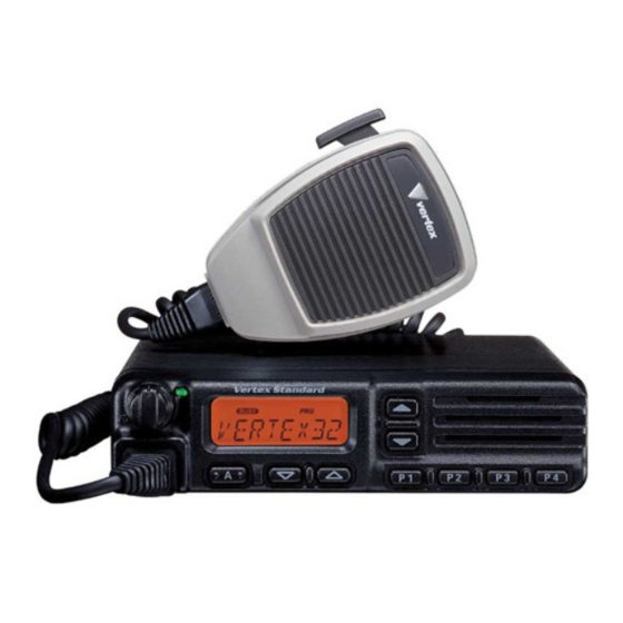
Introduction
The VX-3200V is carefully aligned at the factory for the specified performance across the
frequency range specified for each version. Realignment should therefore not be necessary
except in the event of a component failure, or altering version type. All component
replacement and service should be performed only by an authorized Vertex Standard
representative,or the warranty policy may be void.
The following procedures cover the sometimes critical and tedious adjustments that are not
normally required once the transceiver has left the factory. However, if damage occurs and
some parts subsequently are placed, realignment may be required. If a sudden problem
occurs during normal operation, it is likely due to component failure; realignment should not
be done until after the faulty component has been replaced.
We recommend that servicing be performed only by authorized Vertex Standard service
technicians who are experienced with the circuitry and fully equipped for repair and
alignment. Therefore, if a fault is suspected, contact the dealer from whom the transceiver
was purchased for instructions regarding repair. Authorized Vertex Standard service
technicians realign all circuits and make complete performance checks to ensure compliance
with factory specifications after replacing any faulty components.
Those who do undertake any of the following alignments are cautioned to proceed at their
own risk. Problems caused by unauthorized attempts at realignment are not covered by the
warranty policy. Also, Vertex Standard reserves the right to change circuits and alignment
procedures in the interest of improved performance, without notifying owners.
Under no circumstances should any alignment be attempted unless the normal function and
operation of the transceiver are clearly understood, the cause of the malfunction has been
clearly pinpointed and any faulty components replaced, and realignment determined to be
absolutely necessary.
The following test equipment (and thorough familiarity with its correct use) is necessary for
complete realignment. Correction of problems caused by misalignment resulting from use of
improper test equipment is not covered under the warranty policy. While most steps do not
require all of the equipment listed, the interactions of some adjustments may require that
more complex adjustments be performed afterwards.
Do not attempt to perform only a single step unless it is clearly isolated electrically from all
other steps. Have all test equipment ready before beginning, and follow all of the steps in a
section in the order presented.
Required Test Equipment
RF Signal Generator with calibrated output level at 1000MHz
Deviation Meter (linear detector)
In-line Wattmeter with 5% accuracy at 1000MHz
50-Ω RF Dummy Load with power rating 100W at 1000MHz
4-Ω AF Dummy Load
VX-3200V Alignment
1/6
FCC ID: K66VX-3200V-2
Alignment
Vertex Standard Co., Ltd.
Advertisement
Table of Contents

Related Manuals for Yaesu VX-3200V


Summary of Contents for Yaesu VX-3200V
- Page 1 VX-3200V Alignment Introduction The VX-3200V is carefully aligned at the factory for the specified performance across the frequency range specified for each version. Realignment should therefore not be necessary except in the event of a component failure, or altering version type. All component replacement and service should be performed only by an authorized Vertex Standard representative,or the warranty policy may be void.
- Page 2 FCC ID: K66VX-3200V-2 Alignment Regulated DC Power Supply (standard 13.8V DC, 15A) Frequency Counter with 0.1ppm accuracy at 1000MHz AC Voltmeter DC Voltmeter VHF Sampling Coupler IBM PC / compatible Computer Oscilloscope Vertex Standard VPL-1 Connection Cable & Alignment program Alignment Preparation &...
- Page 3 FCC ID: K66VX-3200V-2 Alignment AF Generator Ground (Fig 2: J1502 connection for the modulation adjustment) The transceiver must be programmed for use in the intended system before alignment is attempted. The RF parameters are loaded from the file during the alignment process. [Important] In order to facilitate alignment over the complete switching range of the equipment it is recommended that the channel data in the transceiver is preset as the chart below.
- Page 4 FCC ID: K66VX-3200V-2 Alignment The alignment tool outline Installation the tool This alignment tool consists,MS-DOS based, only one execute file " svc47.exe ". You make a directly as you think fit, and copy this file. That is all of the installation process. Boot the tool Change directly and input in command line, "...
- Page 5 FCC ID: K66VX-3200V-2 Alignment Press [Enter] on “[2] VCO Deviation” to align VCO Deviation. Select the Channel 1 in alignment range. Adjust the AF generator output level to 388mVrms(-6dBm) at 1 kHz to the pin3 of the J1502 (D-sub 9pin). Press the [Space] key on the keyboard to activate the transmitter.
- Page 6 FCC ID: K66VX-3200V-2 Alignment DCS Deviation (Wide): 0.60[kHz](±0.1[kHz]) DCS Deviation (Narrow): 0.30[kHz](±0.1[kHz]) The actual DCS deviation will increase around 20% based on the above alignment as follows, Actual DCS Deviation (Wide): 0.70[kHz] Actual DCS Deviation (Narrow): 0.35[kHz] [1] Common RX - [0] Tight NSQL This parameter is used to align the noise level in squelch Tight.
Need help?
Do you have a question about the VX-3200V and is the answer not in the manual?
Questions and answers