
Related Manuals for EZY SWITCH SMS-8-GPS


Summary of Contents for EZY SWITCH SMS-8-GPS
- Page 1 EZY SWITCH LIMITED SMS-8-GPS System Monitor Installation Manual Applicable for firmware version 1.1...
-
Page 2: Table Of Contents
Warranty Appendix One Table of User Selected Input and Output Names Detailed Explanation of Input Delays Trouble Shooting Guide Appendix Two SMS-8-GPS Application Notes (Shore Power) SMS-8-GPS Application Notes (Intruder Alarm) SMS-8-GPS Application Notes (Intruder Alarm) SMS-8-GPS Application Notes (Air Conditioner / Heating) - Page 3 Ezy Switch SMS-8-GPS Installation & Operation Manual Features - Model SMS-8 • Receive text messages on your cell phone alerting you to potential problems anywhere in the world • Send commands to control lights, pumps, appliances, air conditioning, etc. via text message from your cell phone •...
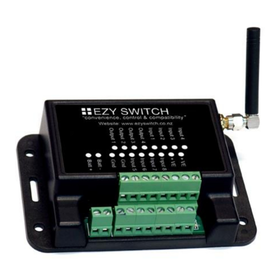
- Page 4 Ezy Switch SMS-8-GPS Installation & Operation Manual Connections Upper Tier Terminals Lower Tier Terminals SMS-8 Terminal Electrical Specifications Batt + = Battery positive 10 to 30vdc Batt – = Battery negative Outputs = sink max 400 Ma each Positive Inputs (Inputs 1, 2, 3 & 4) max Input voltage = 36vdc...
-
Page 5: Outputs
Ezy Switch SMS-8-GPS Installation & Operation Manual System SIM Card 3G Aerial GPS Aerial Ezy Switch Ltd Terminal 11 Terminal 18 Terminal 1 Terminal 3 Terminal 10 Signal LED Signal LED: If the LED flashes once every 1 second, this indicates the cellular network cannot be found (out of GSM coverage range). - Page 6 Ezy Switch SMS-8-GPS Installation & Operation Manual Outputs The SMS-8-GPS has four (4) Outputs. The Outputs are open collector rated at 400ma (max) and will short to GND when turned on. Therefore a Relay may need to be used for some applications.
-
Page 7: Inputs
Ezy Switch SMS-8-GPS Installation & Operation Manual Inputs The SMS-8-GPS has eight (8) Inputs. Four are Positive switching (to Battery+ or VE+) and four are Negative switching (to Ground -). Note: Two Battery+ (or VE+) and two Ground- (Gnd) terminals are provided on the SMS-8-GPS for convenience. However, any battery or ground on the vessel common to the SMS battery power supply can be used for connection. -
Page 8: Getting Started - Setting Up Initial User
Ezy Switch SMS-8-GPS Installation & Operation Manual !! IMPORTANT !! Setting up system for the first time: Please ensure the SIM card does NOT have a PIN number or is locked has been ACTIVATED with the network provider, insert into SIM slot on the back (see page 5) and power the unit up. -
Page 9: Adding A User
Ezy Switch SMS-8-GPS Installation & Operation Manual Commands Adding a User (Note: Setting up the first user page 8 must be done first) Add user +??XXXXXXXX Country Code page 8) Command: (see If the user is already in the list, the system responds with:... -
Page 10: Removing The Administrator
Command: (System default = On) If Text all is On the SMS-8-GPS will text all user that have been programmed into the unit with the reply to the command. If Text all is Off the SMS-8-GPS will only text the number that initiated the command with the reply. -
Page 11: Turn All Texts Off And Disable Inputs
Ezy Switch SMS-8-GPS Installation & Operation Manual PLEASE NOTE: This command does not affect the inputs all Input changes will only be sent to users that have been programmed into the unit. Turn all Input Text’s OFF With alerts turned off the device will NOT text every time any Input changes but the Inputs are still active so you can send a “Input status”... -
Page 12: Naming Inputs/Outputs And Changing Names
Once the name has been changed, the particular Input or Output is always referred to by the new name (e.g. Alarm). For commands or status interrogation and the SMS-8-GPS will respond using the new name. Use table on page 22 to record your new Input and Output names. -
Page 13: Change Input To Normally Open Or Normally Closed
Ezy Switch SMS-8-GPS Installation & Operation Manual Change Input to Normally Open or Normally Closed Make INPUT NAME active open (or) closed Command: This command is used to define if the switch wired to the Input is normally open or normally closed. -
Page 14: Link An Input To An Output
Ezy Switch SMS-8-GPS Installation & Operation Manual Link an Input to an Output Link INPUT NAME to OUTPUT NAME Command: (Example: Link alarm to siren) The system responds with: The INPUT NAME has been linked to OUTPUT NAME To clear a link... -
Page 15: Turn An Output On Or Off
Ezy Switch SMS-8-GPS Installation & Operation Manual Turn an Output ON or OFF Turn OUTPUT NAME on (or) off Command: (Example: Turn Generator on) If everything is fine, the system responds with: OUTPUT NAME has been turned off (or) on This command is used to turn on/off Outputs. -
Page 16: Turn An Output On For A Set Time
Ezy Switch SMS-8-GPS Installation & Operation Manual The OUTPUT NAME is now noninverted Make an Output pulse On and Off Make OUTPUT NAME pulse XX secs Command: This sets the output pulse time, XX can be between 1 and 99 seconds... -
Page 17: Make Output Public
Ezy Switch SMS-8-GPS Installation & Operation Manual Make an output public This command is used to make an output public which means it can be controlled by anyone and not just a programmed user. This could be used for a gate for example. -
Page 18: Set Battery Alarm Trigger Voltage
Ezy Switch SMS-8-GPS Installation & Operation Manual The system responds with: All linked outputs have been cleared Set Battery Alarm Trigger Voltage Change battery alarm to XX.X Command: Where XX.X can be between 8 and 30 volts The system responds with: The low voltage alarm has been set to XX.X volts and the alarm has been reset... -
Page 19: Latching / Non-Latching Battery Alarm
Ezy Switch SMS-8-GPS Installation & Operation Manual Set the battery alarm as a latched or non-latched alarm If the battery alarm is set to latching then once the battery alarm has been triggered the Reset Battery Alarm command needs to be set to reset the latched alarm. If it is set to non- latching the battery alarm will reset once the battery voltage has increased by .5 volts. -
Page 20: Get Firmware Version
Ezy Switch SMS-8-GPS Installation & Operation Manual Masking Alive texts. (only available in ver 1.6 or later) This feature allows you to mask the Alive text so only the programmed users will receive the Alive text and not all users. The default setting is all users will receive the alive text but once this command has been sent only the programmed numbers will receive the text. -
Page 21: Gps Functions
Ezy Switch SMS-8-GPS Installation & Operation Manual GPS Functions The SMS-8GPS can send a text giving it’s current GPS location at any time. To get the current location on demand: Command: The system responds with: (example) Current location is https://www.google.com/maps/place/41.1019148S,174.8678127E... - Page 22 To turn this feature off: gps alarm off Command: The system responds with: The GSP home alarm has been turned off The GPS checks the GPS location every 3 minutes, if the GPS signal is lost it will try for a further 15 minutes the send the following text: The GPS signal has been lost Once the signal has been found the following text will be sent:...
-
Page 23: Warranty
Ezy Switch SMS-8-GPS Installation & Operation Manual CONDITIONS OF WARRANTY Penguin Electronics Ltd (the manufacturer) warrants that all of its products are free of defects. Any apparent fault will be rectified free of charge by Penguin Electronics Ltd for a... -
Page 24: Appendix One
Ezy Switch SMS-8-GPS Installation & Operation Manual Appendix One: Record Your Names for all Inputs and Outputs Active Input Default [Name] (Up to 20 characters ) Latched Linked Open Yes No Name Closed input1 Input2 Input3 Input4 Input5 Input6 Input7... -
Page 25: Trouble Shooting Guide
Ezy Switch SMS-8-GPS Installation & Operation Manual Trouble Shooting Guide PROBLEM CAUSE POSSIBLE SOLUTION LED not flashing No power Check power supply LED fast flashes Cannot find the GSM network 1. Replace aerial with high gain (every 1 second) aerial and never slow 2. -
Page 26: Sms-8-Gps Application Notes (Shore Power)
Ezy Switch SMS-8-GPS Installation & Operation Manual Appendix Two: SMS-8-GPS Application Notes Simple Shore Power Monitoring An inexpensive and effective means to monitor your vessel’s shore power connection is to purchase a 12v DC power supply as typically used to power cordless phones or video games - the type normally available at retailers and electronics suppliers. -
Page 27: Sms-8-Gps Application Notes (Intruder Alarm)
Intruder Alarm Systems The following configurations define possible solutions for intruder alarms. Like all other alerts provided by the SMS-8-GPS, these should be disabled prior to you entering the premises. This is easily accomplished by issuing the text command: Alerts off... -
Page 28: Sms-8-Gps Application Notes (Intruder Alarm)
Ezy Switch SMS-8-GPS Installation & Operation Manual Door and Window Alarms Alarms sensors for doors and windows generally consist of magnetically held switches. The contacts are normally-closed (NC). If a door/window is opened the circuit is opened generating an alarm. An alarm is also generated if the wire is cut between the sensor and the monitoring system opening the circuit. -
Page 29: Sms-8-Gps Application Notes (Air Conditioner / Heating)
Type4: If the brand requires that the Output be pulsed On and Off to turn the Air-Con On and pulsed On and Off to be turned Off. The SMS-8-GPS has a special command for this type. 1. Connect the Air-Con to Output1 2. - Page 30 © All technologies, design and Intellectual property is owned by Penguin Electronics Ltd New Zealand Version 1.1...
Need help?
Do you have a question about the SMS-8-GPS and is the answer not in the manual?
Questions and answers