Table of Contents
Advertisement
Quick Links
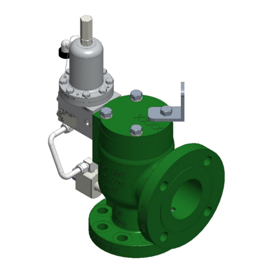
F7000 / F8000 SERIES
PILOT-OPERATED
SAFETY RELIEF VALVE (GAS/LIQUID)
F7040: PLASTIC-SEATED, FULL BORE
F8040: PLASTIC-SEATED, REDUCED BORE
F7050: ELASTOMER-SEATED, FULL BORE
F8050: ELASTOMER-SEATED, REDUCED BORE
INSTALLATION,
OPERATION, & MAINTENANCE MANUAL
Revision:
V
Date of Issue:
Dec. 16, 2021
jwo
GG
Approved by:
Engineering Projects Dir.
Sr. Design Eng.
Advertisement
Table of Contents

Subscribe to Our Youtube Channel
Related Manuals for Flow Safe F8000 Series


Summary of Contents for Flow Safe F8000 Series
- Page 1 F7000 / F8000 SERIES PILOT-OPERATED SAFETY RELIEF VALVE (GAS/LIQUID) F7040: PLASTIC-SEATED, FULL BORE F8040: PLASTIC-SEATED, REDUCED BORE F7050: ELASTOMER-SEATED, FULL BORE F8050: ELASTOMER-SEATED, REDUCED BORE INSTALLATION, OPERATION, & MAINTENANCE MANUAL Revision: Date of Issue: Dec. 16, 2021 Approved by: Engineering Projects Dir.
-
Page 2: Table Of Contents
INSTALLATION, OPERATION, & MAINTENANCE MANUAL TITLE: F7000 / 8000 Series Rev. V Pilot-Operated Safety Relief Valve Page 2 of 41 TABLE OF CONTENTS Topic Page General ....................3 Description, Operation, Service Envelope, Installation, & Startup Description / Operation ................ 5 Service Envelope ................. -
Page 3: General
FLOW SAFE believes that when maintenance and reassembly is performed as outlined in this manual there is no safety hazard. FLOW SAFE recommends that all valves be placed on a regular maintenance schedule that includes the routine replacement of softgoods. FLOW SAFE recommends softgoods replacement every three years but cautions that each customer make their own determination and set their own schedule based upon use and environment. -
Page 4: Description, Operation, Service Envelope, Installation, & Startup
INSTALLATION, OPERATION, & MAINTENANCE MANUAL TITLE: F7000 / 8000 Series Rev. V Pilot-Operated Safety Relief Valve Page 4 of 41 DESCRIPTION, OPERATION, SERVICE ENVELOPE, INSTALLATION, and STARTUP Conventional / Tubed Pilot: PILOT VALVE PISTON DOME ASSEMBLY CAVITY BODY OUTLET PICKUP INLET TUBE CLOSED... -
Page 5: Description / Operation
This plug reduces the effective flow area of the valve by directing the fluid between the plug O.D. and the nozzle I.D. Flow Safe model numbering system is shown below for easy identification of the F7000 or F8000 product. This is designated on the main valve body’s nameplate for TYPE. -
Page 6: Service Envelope
Pilot valve MAWP’s: 740 psig (F100); 6000 psig (F200, F300, & F500) STORAGE AND HANDLING STORAGE Prior to installation, Flow Safe pressure relief valve assemblies and parts should be stored in a clean, dry environment if possible. Inlet and outlet connections should remain covered until the item is ready for installation. -
Page 7: Installation
The F7000 or F8000 Series safety relief valve should be installed in the upright position per the figure below, in accordance with accepted piping practices. Proper gaskets, lubricants and torques, as specified in field procedures, must be used during assembly of bolted joints. -
Page 8: Remote Sense / Field Test Connection
SET PRESSURE CONSIDERATIONS FOR BACK PRESSURE In general, backpressure has no effect on the flow capacity of the FLOW SAFE F7000 / 8000 Series of pilot-operated valves as long as a critical flow condition exists. The critical flow pressure ratio for a particular gas may be estimated by equations given in API 520 Part I, or by contacting FLOW SAFE Engineering. - Page 9 (MAY CONNECT REMOTE SENSE HERE ON OLDER VALVES WITHOUT ABOVE TEE AND FITTINGS) ISOLATION VALVE, LOCKABLE TYPE TUBING OR PIPE, 1/2”, (REMOTE SENSE PICKUP) *FURNISHED BY INLET FLOW SAFE VESSEL F7000 / F8000 SERIES RECOMMENDED INSTALLATION FOR REMOTE SENSE / FIELD TESTING...
-
Page 10: Startup
Remove the retainer bolt, annular flow plug [if F8000 Series], and seat retainer. Larger F8000 flow plugs may be fitted with a spring pin that locks its position on the piston and retainer. The spring pin should remain in the piston due to an interference fit. - Page 11 INSTALLATION, OPERATION, & MAINTENANCE MANUAL TITLE: F7000 / 8000 Series Rev. V Pilot-Operated Safety Relief Valve Page 11 of 41 LIFTING BRACKET CAP BOLT / LOCKWASHER LINER DOME SPRING SEALS Pilot supply port PISTON SEAL Pilot mounting pad Pilot exhaust port See below piston seal arrangements LINER...
- Page 12 INSTALLATION, OPERATION, & MAINTENANCE MANUAL TITLE: F7000 / 8000 Series Rev. V Pilot-Operated Safety Relief Valve Page 12 of 41 Straight-thread style FTC (legacy): Piston seal (legacy): Integral Module (IM) Construction (legacy):...
-
Page 13: Reassembly Of The F7000/8000 Series Main Valve
NOTE that any scratches, gouges, or particles on the seat may result in a sealing problem. Carefully position retainer plate over the seat. For the F8000 series, position the annular flow plug over the retainer and, if applicable, the spring pin in the piston. Apply Loctite or Vibra-tite to the retainer bolt. -
Page 14: Pilot Valve Maintenance
INSTALLATION, OPERATION, & MAINTENANCE MANUAL TITLE: F7000 / 8000 Series Rev. V Pilot-Operated Safety Relief Valve Page 14 of 41 PILOT VALVE MAINTENANCE F100 PILOT VALVE (See Illustration on Page 15) F100 Disassembly CAUTION: It is extremely dangerous to attempt to disassemble any valve while it remains in service with incoming line pressure. - Page 15 INSTALLATION, OPERATION, & MAINTENANCE MANUAL TITLE: F7000 / 8000 Series Rev. V Pilot-Operated Safety Relief Valve Page 15 of 41 PA CAP PRESSURE ADJUSTMENT (PA) SCREW LOCK NUT PA SCREW SEAL BONNET (WHEN SPECIFIED) VENT / BUG SCREEN SPRING WASHER SPRING BOLT DIAPHRAGM...
-
Page 16: F200 Pilot Valve
INSTALLATION, OPERATION, & MAINTENANCE MANUAL TITLE: F7000 / 8000 Series Rev. V Pilot-Operated Safety Relief Valve Page 16 of 41 F200 PILOT VALVE (See Illustrations on Page 17) F200 Disassembly CAUTION: It is extremely dangerous to attempt to disassemble any valve while it remains in service with incoming line pressure. - Page 17 INSTALLATION, OPERATION, & MAINTENANCE MANUAL TITLE: F7000 / 8000 Series Rev. V Pilot-Operated Safety Relief Valve Page 17 of 41 PA CAP PRESSURE ADJUSTMENT (PA) SCREW LOCK NUT PA SCREW SEAL BONNET (BONNET ≤1480 PSIG SHOWN, SEE DETAIL ‘A’ FOR HP BONNET) HP BONNET SPRING SET SCREW...
-
Page 18: F300 Pilot Valve, Diaphragm-Style (15 To 500 Psig)
INSTALLATION, OPERATION, & MAINTENANCE MANUAL TITLE: F7000 / 8000 Series Rev. V Pilot-Operated Safety Relief Valve Page 18 of 41 F300 PILOT VALVE, DIAPHRAGM-STYLE (15-500 psig) (See Illustration below) F300 (Diaphragm-style) Disassembly CAUTION: It is extremely dangerous to attempt to disassemble any valve while it remains in service with incoming line pressure. - Page 19 INSTALLATION, OPERATION, & MAINTENANCE MANUAL TITLE: F7000 / 8000 Series Rev. V Pilot-Operated Safety Relief Valve Page 19 of 41 F300 (Diaphragm-style) Assembly NOTE: Exercise care in handling softgoods, nozzles, and other sealing surfaces. Confirm pressure setting and associated parts required. Place the valve body in a vise.
-
Page 20: F300 Pilot Valve, Piston-Style (286 To 6000 Psig)
INSTALLATION, OPERATION, & MAINTENANCE MANUAL TITLE: F7000 / 8000 Series Rev. V Pilot-Operated Safety Relief Valve Page 20 of 41 Assemble the pressure adjustment (PA) screw and lock nut into the top of the bonnet. Attach the cap to the PA screw, but do not tighten. Install vent / bug screen into bonnet, ensuring that the male NPT end does not contact the spring. - Page 21 INSTALLATION, OPERATION, & MAINTENANCE MANUAL TITLE: F7000 / 8000 Series Rev. V Pilot-Operated Safety Relief Valve Page 21 of 41 LP Piston Style, 286-1480 psig (legacy): Integral Module (IM) Construction (legacy):...
- Page 22 INSTALLATION, OPERATION, & MAINTENANCE MANUAL TITLE: F7000 / 8000 Series Rev. V Pilot-Operated Safety Relief Valve Page 22 of 41 F300 (Piston-style) Assembly NOTE: Exercise care in handling softgoods, nozzles, and other sealing surfaces. Confirm pressure setting and associated parts required. Place the valve body in a vise.
-
Page 23: F500 Pilot Valve
INSTALLATION, OPERATION, & MAINTENANCE MANUAL TITLE: F7000 / 8000 Series Rev. V Pilot-Operated Safety Relief Valve Page 23 of 41 Install vent / bug screen into the bonnet, and the inlet screen into the body. Assemble the face seals to the external mounting face of the pilot body. The ‘IM’ style body has an additional face seal at the inlet port. - Page 24 INSTALLATION, OPERATION, & MAINTENANCE MANUAL TITLE: F7000 / 8000 Series Rev. V Pilot-Operated Safety Relief Valve Page 24 of 41 Low Pressure: Place piston into the spindle spring and over the end of the spindle. Install diaphragm fastener seal in top of piston and place the diaphragm on top of the piston. Put the diaphragm washer on top of diaphragm.
- Page 25 INSTALLATION, OPERATION, & MAINTENANCE MANUAL TITLE: F7000 / 8000 Series Rev. V Pilot-Operated Safety Relief Valve Page 25 of 41 PA CAP BACKFLOW PREVENTER (BFP) OPTIONS SECTION A-A PRESSURE ADJUSTMENT (PA) BFP NOZZLE, SCREW BLANK LOCK NUT PA SCREW SEAL BONNET (WHEN SPECIFIED) SPRING...
-
Page 26: Pilot Valve Set Pressure Adjustment
Set pressure may be defined in terms of ASME Section VIII or US DOT regulations for natural gas transmission and distribution, subject to the jurisdiction in effect at the particular valve installation. Contact Flow Safe for confirmation of spring range or new spring part number before resetting any pilot to a different set pressure. - Page 27 INSTALLATION, OPERATION, & MAINTENANCE MANUAL TITLE: F7000 / 8000 Series Rev. V Pilot-Operated Safety Relief Valve Page 27 of 41 MAIN VALVE MOUNTING FACE PILOT VALVE DOME ASSEMBLY PRESSURE GAGE INLET PRESSURE GAGE MAIN VALVE FEED PORT, 1/4” NPT PILOT EXHAUST PORT, 1/4”...
-
Page 28: F100 Pilot Valve Adjustment
(See Illustrations on Pages 17 and 27) The set pressure for the F200 Pilot Valve may be adjusted only by turning the pressure adjusting (PA) screw or changing springs. Contact Flow Safe to verify the proper spring for the desired set pressure. -
Page 29: F300 Pilot Valve Adjustment
The set pressure for the F300 pilot valve may be adjusted by turning the pressure adjusting (PA) screw, changing springs, or by exchanging diaphragm-style and piston-style internals. Contact Flow Safe to verify the proper parts for the desired set pressure. Attach pilot valve assembly to the test tank with the cap removed and the pressure adjustment screw turned out to below where the set point is believed to be. -
Page 30: F500 Pilot Valve Adjustment
INSTALLATION, OPERATION, & MAINTENANCE MANUAL TITLE: F7000 / 8000 Series Rev. V Pilot-Operated Safety Relief Valve Page 30 of 41 F500 PILOT VALVE ADJUSTMENT (See Illustrations on Pages 25 and 27) The set pressure for the F500 pilot valve may be adjusted by turning the pressure adjusting (PA) screw, or by changing springs, corresponding diaphragm, or sense piston arrangements. -
Page 31: Pilot Auxiliary Setter Adjustment
(See Illustration below) The set pressure for the pilot auxiliary setter may be adjusted by turning the pressure adjusting (PA) screw or changing springs. Contact Flow Safe to verify the proper spring for the desired set pressure. The auxiliary setter must be installed on its designated pilot valve when being adjusted. This may be verified by means of matching serial numbers. -
Page 32: Supplemental Testing And Accessories
To enable separate control of pressure sources to the main valve dome and inlet, a hydro test plate (available from FLOW SAFE) should be installed on the pilot mounting pad, as shown in the figure below. -
Page 33: Final Assembly Testing
F300 PILOT VALVE PROPORTIONAL BAND ADJUSTMENT Purpose The FLOW SAFE F300 Series is a modulating-style pilot valve used with the F7000/8000 Series. As received from the factory, the F300 is lockwired to prevent any adjustments to the set pressure. This lockwire is also attached to the proportional band screw (see drawings on Page 18, 20, 21 and 27). -
Page 34: Inservice Testing With The Field Test Connection
INSTALLATION, OPERATION, & MAINTENANCE MANUAL TITLE: F7000 / 8000 Series Rev. V Pilot-Operated Safety Relief Valve Page 34 of 41 INSERVICE TESTING WITH THE FIELD TEST CONNECTION (FTC) CAUTION: Extreme care must be taken when testing or servicing a pressure relief valve used in gas or incompressible fluid service. - Page 35 INSTALLATION, OPERATION, & MAINTENANCE MANUAL TITLE: F7000 / 8000 Series Rev. V Pilot-Operated Safety Relief Valve Page 35 of 41 NOTE: 1. For an F200 snap-acting pilot, pilot valve “reseat” pressure will be that pressure at which the dome gage repressurizes. 2.
-
Page 36: Harguard Clean Pilot Supply Tank
INSTALLATION, OPERATION, & MAINTENANCE MANUAL TITLE: F7000 / 8000 Series Rev. V Pilot-Operated Safety Relief Valve Page 36 of 41 HARGUARD CLEAN PILOT SUPPLY TANK The Harguard clean pilot supply tank isolates critical relief valve parts from a corrosive or dirty system process, and permits only a clean liquid such as glycol and water to enter the pilot and main valve dome. -
Page 37: Troubleshooting Guide
INSTALLATION, OPERATION, & MAINTENANCE MANUAL TITLE: F7000 / 8000 Series Rev. V Pilot-Operated Safety Relief Valve Page 37 of 41 TROUBLESHOOTING GUIDE: Symptom Possible Cause Remedy The main valve Inadequate or uneven bolt torque. Retighten the cap bolts per Section 3.2. leaks around the Sealing surface on cap is damaged. -
Page 38: Softgoods Kits
Kalrez Chemraz Lo-temp nitrile Most common materials listed; contact Flow Safe for availability of other materials. Approximate pressure ranges of plastic seats shown in Section 2.2 on Page 6. Main Valve Softgoods Kit contents: Standard kit Qty. -
Page 39: Pilot Valve Softgoods
These pressure ranges are approximate only. Most common materials listed; contact Flow Safe for availability of other materials. Seals made from other materials noted below. NOTE: Softgoods kits may contain extra O-rings for older part versions that may not be needed. - Page 40 INSTALLATION, OPERATION, & MAINTENANCE MANUAL TITLE: F7000 / 8000 Series Rev. V Pilot-Operated Safety Relief Valve Page 40 of 41 PILOT VALVE SOFTGOODS (cont’d) See Page 39 for terminal digits “D”, “X”, “Y”, & “Z”. F300 Softgoods Kits: F300-DI-DXYZ Diaphragm-style (15 - 500 psig) Contents (See drawings on Page 18): Qty.
- Page 41 INSTALLATION, OPERATION, & MAINTENANCE MANUAL TITLE: F7000 / 8000 Series Rev. V Pilot-Operated Safety Relief Valve Page 41 of 41 PILOT VALVE SOFTGOODS (cont’d) See Page 39 for terminal digits “D”, “X”, “Y”, & “Z”. F500 Softgoods Kits: F500-LPS-DXYZ LP (to 285 psig) F500-LPT-DXYZ LP (to 285 psig), with set point indicator Contents (See drawings on Page 25):...
Need help?
Do you have a question about the F8000 Series and is the answer not in the manual?
Questions and answers