Table of Contents

Related Manuals for Flow Safe F84L Series


Summary of Contents for Flow Safe F84L Series
- Page 1 F84L SERIES LIQUID RELIEF VALVE • PLASTIC SEATED • - 2, - 3, - 4, - 8, - G, - J Orifices INSTALLATION, OPERATION, & MAINTENANCE MANUAL Revision: Date of Issue: Sep. 16, 2016 Approved by: Project Designer Engineering Projects Dir.
-
Page 2: Table Of Contents
Test Equipment ................. 8 Setting / Adjustment Tolerances ............8 Set Pressure Adjustment ..............9 Seat Tightness .................. 9 Lift Lever Operation ................9 Accessories..................10 Troubleshooting Guide ..............11 Illustrations F84L Series Valve Assembly Illustrations............ 13... -
Page 3: General
This manual is intended to provide users with direction and guidance for the maintenance of FLOW SAFE F84L Series liquid relief valves. This manual indicates the proper method of valve disassembly, soft goods replacement, and valve reassembly. FLOW SAFE provides this manual as a guideline and reference only. -
Page 4: Description, Operation, Service Envelope, Installation, & Startup
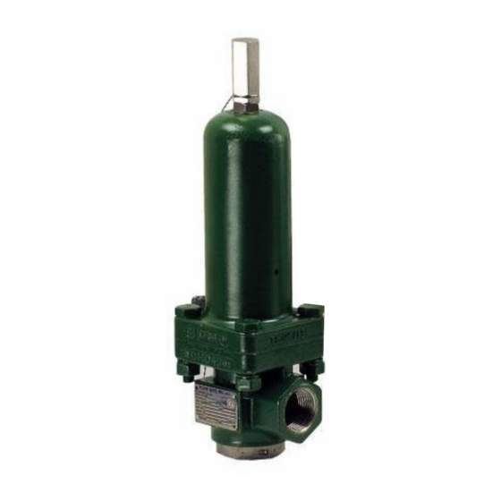
INSTALLATION, and STARTUP DESCRIPTION / OPERATION The FLOW SAFE F84L Series liquid relief valve is a direct-acting spring-loaded relief valve, suitable for liquid service. The Type F84L is plastic-seated with elastomeric seals. Orifice sizes are available in -2, -3, -4, -8, -G, and -J with set pressures from 30 to 24,277 psig (depending on the orifice size). -
Page 5: Service Envelope
Prior to installation, check that the set pressure on the nameplate is as required, and meets the system requirements. The F84L Series liquid relief valve should be installed in the upright position per the figure on the next page, as close as possible to the pressure source, to minimize pressure losses between the system and the valve. -
Page 6: Startup
F84L Series Liquid Relief Valve Rev. H Page 6 of 15 F84L Series valves are balanced against superimposed backpressure, so that the set pressure will not change with backpressure. Make sure that the inlet piping/flanges have an opening equal to or greater than the valve's inlet diameter. Make sure that there are no obstructions like gaskets, fittings, etc., in the flow path to restrict... -
Page 7: Valve Maintenance
Replace the softgoods per the instructions in Section 3.2. • Replacement parts may be found in the appropriate FLOW SAFE softgoods kit, as listed in Section 5.0 of this manual. REASSEMBLY Reassembly of these valves is basically the reverse of the disassembly. -
Page 8: Valve Testing And Adjustment
INSTALLATION, OPERATION, & MAINTENANCE MANUAL TITLE: F84L Series Liquid Relief Valve Rev. H Page 8 of 15 a.) Bolted-bonnet valve sizes and -2 with retained seat: Carefully install new drag seal / spindle seal(s) in grooves on spindle. Desco 600 grease should be applied to the outside of these O- rings, except that, for all -2 valves and –3, –4, and –8 valves below 100 psig, Dow Corning... -
Page 9: Set Pressure Adjustment
INSTALLATION, OPERATION, & MAINTENANCE MANUAL TITLE: F84L Series Liquid Relief Valve Rev. H Page 9 of 15 SET PRESSURE ADJUSTMENT 1. Set pressure is defined as 93% of the “gush” (pop) pressure. This corresponds to NOTES: the first steady stream if valve is being set on a low-capacity test system. -
Page 10: Accessories
Polyurethane EPR / EPDM Kalrez Chemraz Lo-temp nitrile Most common materials listed; contact Flow Safe for availability of other materials. Bushing seal and rear seal are Teflon. SOFTGOODS KIT CONTENTS (See Pages 13 through 15) Standard SG Kit: Qty. Lift Lever SG Kit (includes Std. items): -3 to -J Description Qty. -
Page 11: Troubleshooting Guide
INSTALLATION, OPERATION, & MAINTENANCE MANUAL TITLE: F84L Series Liquid Relief Valve Rev. H Page 11 of 15 TROUBLESHOOTING GUIDE: Symptom Possible Cause Remedy Inadequate bushing torque. Tighten until the bushing bottoms firmly The valve leaks around on the body. the bushing. - Page 12 INSTALLATION, OPERATION, & MAINTENANCE MANUAL TITLE: F84L Series Liquid Relief Valve Rev. H Page 12 of 15 TROUBLESHOOTING GUIDE (continued): Symptom Possible Cause Remedy Spindle is stuck closed. Disassemble the valve and examine the The valve does not sliding surfaces. If damaged, replace.
-
Page 13: F84L Series Valve Assembly Illustrations
INSTALLATION, OPERATION, & MAINTENANCE MANUAL TITLE: F84L Series Liquid Relief Valve Rev. H Page 13 of 15 F84L SERIES VALVE ASSEMBLY ILLUSTRATIONS... - Page 14 INSTALLATION, OPERATION, & MAINTENANCE MANUAL TITLE: F84L Series Liquid Relief Valve Rev. H Page 14 of 15 F84L SERIES VALVE ASSEMBLY ILLUSTRATIONS (continued) See Page 15 for typical lift lever assembly.
- Page 15 INSTALLATION, OPERATION, & MAINTENANCE MANUAL TITLE: F84L Series Liquid Relief Valve Rev. H Page 15 of 15 F84L SERIES VALVE ASSEMBLY ILLUSTRATIONS (continued) F84L Series Manual DUS.FS.0015 03.21...
Need help?
Do you have a question about the F84L Series and is the answer not in the manual?
Questions and answers