Table of Contents
Advertisement
Quick Links
Advertisement
Table of Contents

Related Manuals for Astra G-120E


Summary of Contents for Astra G-120E
- Page 1 ASTRA MACHINERY PLANT AB • ANNO 1929 HEATING BOILERS Astra G-120E INSTALLATION AND OPERATION MANUAL CONTACT INFORMATION OF THE FACTORY: MACHINERY PLANT “ASTRA” AB ULONŲ G. 33, LT-62161 ALYTUS, LITHUANIA TEL.: +370 315 75449 FAX: +370 315 52265 E-MAIL: INFO@ASTRA.LT...
-
Page 2: Table Of Contents
TABLE OF CONTENTS 1. SAFETY REQUIREMENTS .................. 3 2. TECHNICAL DESCRIPTION ................4 • General View of the Boiler ........................4 • Technical Data of the Boiler ......................... 5 • Ceramic Elements of the Boiler ......................6 • Turbulence Plates ..........................6 3. -
Page 3: Safety Requirements
INSTALLATION AND OPERATION MANUAL This user manual was compiled following the requirements of EN 12171 “Heating systems in buildings. Procedure for the preparation of documents for operation, maintenance and use. Heating systems not requiring a trained operator”. 1. SAFETY REQUIREMENTS 1.1. -
Page 4: Technical Description
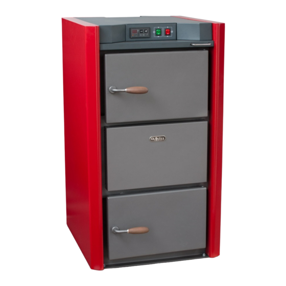
HEATING BOILERS: Astra G-120E 2. TECHNICAL DESCRIPTION • GENERAL VIEW OF THE BOILER Fig. 1 General view of the boiler A – front view; B – rear view with detached backside panel; C – top view with detached backside panel; D - section. -
Page 5: Technical Data Of The Boiler
INSTALLATION AND OPERATION MANUAL • TECHNICAL DATA OF THE BOILER Indicator value Name of indicator Astra G-120E Nominal heat output, kW Class of boiler according to EN 303-5 Class of protection against electric impact Efficiency rate,% 81-89 Power of emergency cooling system, kW Water volume in the boiler, l Setting range of the temperature regulator, °C... -
Page 6: Ceramic Elements Of The Boiler
• TURBULENCE PLATES Turbulence plates – a technology invented and patented by “Astra” engineers, used for capturing more heat from the hot exhaust smoke. It forces the exhaust smoke to hold, become turbulent and thus transfer more heat to the adjacent heat exchanger. -
Page 7: Intended Use
INSTALLATION AND OPERATION MANUAL Turbulence plates decrease the temperature of the exhaust smoke. The boiler can be operated without the plates, but then greater losses of heat through the chimney will occur. The bottom aperture 6 (Fig. 3) is intended for removal of cleaning residues. 3. -
Page 8: Installation
HEATING BOILERS: Astra G-120E 5. INSTALLATION • ACCUMULATION TANK These solid fuel boilers are intended to be fully loaded during the operation; the most efficient mode of their exploitation is at the nominal or maximum heat output. It is advisable to install an accumulation tank of sufficient size in their proximity, which could accumulate the excessive heat. - Page 9 INSTALLATION AND OPERATION MANUAL Fig. 5 Principle scheme of the house heating system including heat accumulation...
-
Page 10: Requirements For Connection Of The Boiler To The Heating System
HEATING BOILERS: Astra G-120E control processor, room or/and outside temperature sensors, 3-way servo drive, mixing valve, underfloor heating system, radiators, piping, fittings. The programmed processor controls a 3-way mixing valve, which allows more or less heat (45- 60°C) into the radiators, according to demand. This way of heat consumption allows the heating of the house as long as the tank stores heat independently from the boiler. -
Page 11: Circuit Diagram Of The Boiler
INSTALLATION AND OPERATION MANUAL • CIRCUIT DIAGRAM OF THE BOILER 220 V KR-4.4 Fig. 6 Circuit diagram of the boiler S1 - power supply switch; S2 – fan switch; SK – emergency ventilator shutdown 95°C thermostat; F - fuse; M1 - smoke exhaust fan;; M2 - air supply fan;... -
Page 12: Removing The Rooftop Cover Of The Boiler
HEATING BOILERS: Astra G-120E the socket on the rear control panel indicated with symbol . • REMOVING THE ROOFTOP COVER OF THE BOILER Before detaching the rooftop panel of the boiler, unplug it from the electrical supply. Take off the loose cover 22 (Fig. -
Page 13: Installation Of The Boiler Room
INSTALLATION AND OPERATION MANUAL Do not forget to keep the returning water temperature as high as possible, at least 65°C or even higher! It is necessary to assure that a thermometer is installed on the returning water pipe, in order to be able to observe this temperature at any time! •... -
Page 14: Fuel
HEATING BOILERS: Astra G-120E or less degrees. Draught of the chimney can also be negatively affected by various obstructions near the building: trees, hills, other buildings. Fig. 8 presents the recommended minimal angles between the chimney, nearby objects and the horizon. Angles larger than those indicated will cause reduction of draught of the chimney. -
Page 15: Operation
INSTALLATION AND OPERATION MANUAL 7. OPERATION • FRONT CONTROL PANEL START PAUSE Fig. 9 Front control panel 1. Electronic boiler regulator; 2. Green button for switching the voltage of the boiler on and off; 3. Red button for switching on the ventilator. The front control panel has an electronic boiler regulator 1, a green button for switching voltage to the boiler on/off 2 and a red button for switching on the ventilator 3. -
Page 16: Electronic Boiler Regulator Kr-4.4
HEATING BOILERS: Astra G-120E • ELECTRONIC BOILER REGULATOR KR-4.4 The electronic boiler regulator KR-4.4 is designed for controlling a solid fuel boiler. It controls the ventilator in accordance with the PID regulation law and the circulation pump of the system, by position “on-off”. The regulator adjusts the rotation speed of the ventilator using the impulse method, thus intensifying or slowing down the burning process. -
Page 17: Preparation For Firing
INSTALLATION AND OPERATION MANUAL stemming from the front control panel and transferred L1, N- reguliatoriaus maitinimas; KR-4.4 Rear panel of the regulator to the regulator, is switched on when switches 2 and L2 - ventiliatoriaus maitinimas; 3 (Fig. 9) are in the position ON and the emergency L3 - įtampa į... -
Page 18: Fire Bed And Tips For Effective Boiler Stoking
HEATING BOILERS: Astra G-120E The first time, kindle the boiler using only paper and small pieces of wood in order to safely remove the moisture remaining in the ceramic elements. Switch on the voltage, using button 2 on the front control panel. The boiler water temperature indicator will light up on the electronic regulator (Fig. -
Page 19: Regulation Of The Boiler Temperature
• DESCRIPTION OF THE SMOKE TEMPERATURE SENSOR FUNCTION The smoke temperature sensor is mounted in Astra boilers in order to: 1) help the controller achieve the optimal smoke temperature, 2) turn off the ventilator after firing in the boiler is accomplished, 3) turn off the circulation pump after the firing... -
Page 20: Cleaning The Boiler
HEATING BOILERS: Astra G-120E Although the optimal smoke temperature is set up in the factory, we recommend that you set the temperature by yourself once again after the installation of the boiler at its operation place. In this way, a more precise temperature will be set up with respect to the fuel used, draught and other peculiarities of the installation. -
Page 21: Possible Faults
INSTALLATION AND OPERATION MANUAL Fallen soot and residues should be swept through the bottom inspection aperture 6 (Fig. 3). After finishing of cleaning, place the turbulence plates into the initial positions and seal all lids. Clean the smoke exhaust chamber 26 (Fig. 1). Check the primary air supply channels 30 (Fig. 1) against clogging. For this purpose, remove the front side panel as shown in Fig. -
Page 22: Warranty And Its Validity Terms
HEATING BOILERS: Astra G-120E Release the fixing bolt 2 (Fig. 15) with a spanner No 13. Insert a spanner No 17 into the notch 3 and turn the screw 5 into a required direction until a door seals completely. For a support regulation, first, release the fixing nut 7 with a spanner No 19. -
Page 23: Acceptance Certificate
INSTALLATION AND OPERATION MANUAL 10. ACCEPTANCE CERTIFICATE The heating boiler Astra G-120E, serial No........, conforms to the technical documentation and requirements of standard EN 303-5 and is approved as fit for operation. Manufacturing date 201 ....................L. S. Head of Quality Service .................... -
Page 24: Warranty And Post-Warranty Repair Card
DECLARATION OF CONFORMITY Manufacturer: Machinery plant “Astra” AB Address: Ulonu g. 33, 62161 Alytus, Lithuania Product designation: heating boilers Astra G-120E We declare that the above-mentioned products conform to the requirements of directives 97/23/EEC Article 2.3 and 2006/95 EEC. The following standards were applied for the above-mentioned products:...
Need help?
Do you have a question about the G-120E and is the answer not in the manual?
Questions and answers