Table of Contents

Subscribe to Our Youtube Channel
Related Manuals for Audio Technica ATUC-M43H/58H


Summary of Contents for Audio Technica ATUC-M43H/58H
- Page 1 Instruction manual Digital Conference System ATUC-50 Gooseneck Microphone with LED Ring ATUC-M43H/58H Discussion Unit ATUC-50DU Interpretation Unit ATUC-50INT Control Unit ATUC-50CU Integration Unit ATUC-50IU Link Extender ATLK-EXT165...
-
Page 2: Table Of Contents
............35 Features of ATUC-M43H/58H ..........7 Starting up and logging in to Web Remote ......35 Optional products (sold separately by Audio Technica) ..7 About Web Remote Home screen .......... 35 Connection example of digital conference Configuring detailed system settings system ATUC‑50 ............ - Page 3 Information.......... 59 Troubleshooting ........... 59 ATUC-50CU ................59 ATUC-50DU/INT ..............60 Web Remote ................61 ATUC-50IU ................61 ATLK-EXT165 ................ 61 Error messages ............. 62 Specifications ........66 ATUC‑50CU specifications ........66 General specifications ............66 Input/output specifications ........... 67 ATUC‑50DU/INT specifications ......
-
Page 4: Introduction
Introduction About this manual Included accessories for the ATUC-50CU About the information in this manual The images and screenshots shown in this manual may differ from The following accessories and documentation are provided. the actual product. • AC power cord •... -
Page 5: System Placement
System placement Installing the CU(s) in a rack Rack requirements for the CU • EIA standard compatible 19-inch rack • 1U-size rack mounting • Rack equipped with safety guardrails to support the CU and a board on which the CU is to be placed W hen installing the CU(s) in a rack, keep the temperature within the rack below 45°C (113°F). -
Page 6: Atuc-50 System
ATUC-50 System Features • Talk mode: Manual mode, Voice activation mode • Web Remote enables you to easily change settings and control attendees' right to talk during conference Features of ATUC‑50 system • Up to 4 channels (WAV: up to 4 channels, MP3: up to 2 channels) can be recorded on a USB device (mass storage device) •... -
Page 7: Features Of Atlk-Ext165
Features of ATLK‑EXT165 • Connects to any Audio Technica device, such as a control unit (ATUC-50CU), or discussion unit (ATUC-50DU), and is equipped with two RJ-45 terminals that can expand the discussion system • Remote mode that automatically starts from the control unit (ATUC-50CU) •... -
Page 8: Connection Example Of Digital Conference System Atuc-50
Connection example of digital conference system ATUC-50 Windows/Mac Tablet Web Remote Web Remote Control Control CU (extension) Router Switching hub Speaker CU (extension) Amplifier USB device (mass storage device) to be used for recording/SFX CU (primary) Microphone Recorder CD player (Maximum 50 units)* (Maximum 50 units)* ➤... -
Page 9: Part Names And Functions
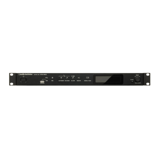
Part Names and Functions ATUC-50CU Front panel ① ② ③ ④ ⑤ ⑥ ⑦ ⑧ ⑨ ⑩ ⑪ ⑫ ① Power switch NOTICE • If you remove the USB device (mass storage device) Turns the power of the CU on and off. while in a recording state or recording-pause state, the recorded file may not be written correctly. - Page 10 ⑫ Jog dial/ENTER button 3 Conference preparation (Pst) Rotate the jog dial to select the desired item and then press the ENTER button to confirm. Rotating the jog dial also adjusts the setting values. • Locking the operation buttons (Key Lock function) •...
-
Page 11: Rear Panel
Rear panel * The serial number label is located on the top panel. ⑬ ⑭ ⑮ ⑯ ⑰ ⑱ ⑲ ⑳ ㉑ ㉒ ⑯ Analog output (balanced) terminals: OUTPUT 1-4 (BAL) NOTICE • Refer also to the instruction manuals supplied with the external devices. -
Page 12: Atuc-50Du
ATUC-50DU (talk) button ⑦ ① Press this button to send a request to talk. Press the button again ② to finish talking or cancel the request to talk. DUs designated as a priority DU can cut other DU speakers short and mute other ③... -
Page 13: Atuc-50Int
ATUC-50INT ① ② ③ VOL. ④ ⑤ ⑥ ⑦ ⑧ ① Display • Character on the left: Displays the current monitor channel. F: Monitors speech from the floor channel (speech from all meeting participants). 1: Monitors speech from language group 1. •... -
Page 14: Common To Atuc-50Du/Int
Common to ATUC-50DU/INT ATUC-M ① ② ③ ① Microphone ① ② Ring LED Lights red when the microphone is activated. Blinks red while waiting to talk. ③ Connector ② ③ ④ ⑥ ⑤ ① Headphone jack Speech from the selected monitor channel is output. ②... -
Page 15: Atuc-50Iu
ATUC-50IU φ5 φ5 φ12 ① ② ⑥ ③ ⑦ ④ ⑧ ⑤ φ5 ⑨ Because the IU is intended to be embedded in a table, etc., when it is used, the user interfaces, such as displays, operating terminals, and input/ output terminals, can be customized according to their usage environment. - Page 16 ④ Status output terminal Terminal Signal name Explanation number color Talk ON: Close TALK LED : Talk OFF: Open OPEN/CLOSE Requesting to talk (waiting): blinks Talk request is rejected: blinks quickly Terminal for AT8657/LED and U891RCx Talk ON: +5 V TALK LED : Talk OFF: 0 V LOW/HI...
- Page 17 page 56) ⑨ Audio Technica LINK terminal Connect the Audio Technica products and configure the system. NOTICE • Power is supplied to external devices from the 5 V pin (22); however this pin has a maximum rating of +5 VDC at 100 mA. W hen you use this, select a circuit or current limit (resistance value) so that the rating is not exceeded.
- Page 18 Example of a user interface connection 1 2 3 4 5 6 7 8 9 22 23 24 25 26 27 28 29 30 31 32 33 34 35 36 37 38 39 TALK LED FLOOR LANGUAGE 1 LANGUAGE 2 LANGUAGE 3 CHANNEL VOL.
- Page 19 When using with the AT8657/LED ATUC-50IU COLD TALK LED: LOW/HI TALK ON (INVERT) When using with the U891RCx ATUC-50IU BK: GND WH: LED CONTROL COLD BL: CONTACT CLOSURE RD: COLD YL: HOT SH: GND TALK LED: LOW/HI TALK ON • Do the following settings for the U891RCx. SW.FUNCTION: MOM.
- Page 20 • W hen securing on only one side Leave about 2 mm of the screws out when you fasten them to the table, and then hang the IU on them. Slide the IU downward, and then tighten the screws to secure the IU. Suspend screws about 2 mm Tighten screws securely •...
-
Page 21: Atlk-Ext165
Turn off mode switch of EXT → Turn off CU power ② Power indicator ③ Audio Technica LINK Device indicator Indicates the connection status of devices that support Audio Technica LINK. • Connected: Lit • Unconnected: Unlit ④ Data indicator •... -
Page 22: Changing Settings From Atuc-50Cu
Changing settings from ATUC-50CU 18 Time Zone 19 CU Link Status 20 CU Link Mode 21 No.ofExtensionCU 22 Total No.of DU You can change CU settings by selecting “Set” on the HOME screen 23 Total No.of IU of the CU display. Changeable items are as follows. 24 Total No.of INT For more detailed settings, or for individual DU/IU/INT settings, ➤ ... -
Page 23: Entering Letters
Entering letters 06 MicON Trigger All Button, All Voice, Individual 07 MicON Hold Time 1.0 to 10.0 seconds 08 Interrupt Option Cut, Mute ➤ [6] Logging ( page 61) For example, when entering letters from [4] Recorder Setting → 01 Logging On, Off 09 Filename Prefix , follow the procedure below. -
Page 24: Overview Of The Interpretation Unit (Atuc-50Int)
Overview of the Interpretation Unit (1) Interpretation using two languages (2 Languages) (ATUC-50INT) • W hile in the 2 Languages interpretation mode, you can select from three interpretation patterns (see table below). • For instance, when the interpretation pattern “English → Japanese” is set, “F”... - Page 25 (2) Interpretation using three languages (3 Languages) • Out of the three languages, the language of Audio Group 1 is used • W hile in the 3 Languages interpretation mode, you can select from a s t h e k e y l a n g u a g e (i n t h i s c a s e i t i s E n g l i s h) , a n d r e l ay nine interpretation patterns (see table below).
-
Page 26: System Connections And Configuration
System Connections and Configuration Connecting devices W hen securing a DU/INT to a desk or table, use the screw holes (3 holes) on the bottom side of the DU/INT (screw: M3, P=0.5, within 6mm from the bottom side to the tip of the screw). NOTICE •... -
Page 27: Connecting The Dus/Ints Together
Ring connection: • Remove the DU/INT bottom cover to connect the Ethernet cables. W hen removing the bottom cover, pinch Connect as many DUs/INTs as necessary to each of the DU together the latches on both sides. CHAIN A/B terminals and then connect together the 2 DUs/ INTs on both ends of the chain so as to form a ring. - Page 28 Maximum number of connections for each terminal/each CU in Standalone mode Maximum number of terminal connections in a DU CHAIN Total Daisy Chain 100* Ring * The maximum number of units that can be connected is up to 100 units to each terminal on the DU CHAIN by using the EXT. * IUs consume more power than DUs, so the number of units shown in the table cannot be connected.
- Page 29 Daisy-chain connection ATUC-50CU ATUC-50DU ATLK-EXT165 NOTICE • For a CU-DU-DU-…DU-EXT connection, the distance between the [DU-EXT] is L1. • W hen it is EXT-DU-…-DU-DU-, the distance for [EXT-DU] is L3. Relationship of the LAN cable length, number of units connected and number of EXTs required: Daisy chain connection 1-port daisy-chain connection 1-port daisy-chain connection...
- Page 30 2-port daisy-chain connection 2-port daisy-chain connection Length of cables (using DUs) (using IUs) CU-DU DU-DU EXT-DU Maximum Maximum Number of Number Number number of Number of IUs number of DUs of EXTs of EXTs units connected units connected needed needed connected connected (total 50 (total 32 1 to 25 × 2 units 0 units 1 to 16 × 2 units 0 units units) units)
- Page 31 Length of cables 4-port daisy-chain connection (using DUs) 4-port daisy-chain connection (using IUs) EXT- Maximum Maximum CU-DU DU-DU Number Number Number of DUs number of Number of IUs number of of EXTs of EXTs connected units connected units needed needed connected connected A/B: 0 A/B: 0 A/B: 1 to 15 × 2 units (total 50 units A/B: 1 to 10 × 2 units (total 32 units C/D: 1 to 10 ×...
- Page 32 Length of cables 4-port daisy-chain connection (using DUs) 4-port daisy-chain connection (using IUs) EXT- Maximum Maximum CU-DU DU-DU Number Number Number of DUs number of Number of IUs number of of EXTs of EXTs connected units connected units needed needed connected connected A/B: 0 A/B: 0 A/B: 1 to 15 × 2 units (total 50 units A/B: 1 to 10 × 2 units (total 32 units C/D: 1 to 10 ×...
- Page 33 Ring connection ATUC-50CU ATUC-50DU ATLK-EXT165 NOTICE • For a CU-DU-DU-…DU-EXT connection, the distance between the [DU-EXT] is L1. • W hen it is EXT-DU-…-DU-DU-, the distance for [EXT-DU] is L3. Relationship of the LAN cable length, number of units connected and number of EXTs required: Ring connection Length of cables 1-ring connection (using DUs) 1-ring connection (using IUs)
- Page 34 Length of cables 2-ring connection (using DUs) 2-ring connection (using IUs) EXT- Maximum Maximum CU-DU DU-DU Number Number Number of DUs number of Number of IUs number of of EXTs of EXTs connected units connected units needed needed connected connected (total 50 (total 32 1 to 25 × 2 units 0 units 1 to 16 × 2 units 0 units units) units)
- Page 35 NOTICE • W hen connecting DUs/IUs, never exceed the number of connectable DUs/IUs and the connectable length. It may damage the CU or the EXTs. • Depending on the CU settings, you can also connect the DUs/IUs to the CU LINK terminals by configuring them as DU CHAIN C/D terminals.
- Page 36 CU Link connection: ➤ ➤ • You can either daisy-chain ( page 27) or ring ( page Up to 3 CUs can be cascaded (cascade CUs using the CU LINK 27) DUs/INTs to each CU. A/B terminals as shown below). Set one of the CUs as the primary unit.
-
Page 37: Connecting The Microphone Atuc-M To The Du/Int
NOTICE • W hen connecting external devices to IN/OUT terminals, 3 Connecting the microphone ATUC‑M to do so after cutting the phantom power supply of the the DU/INT external devices. If you leave the phantom power supply on, it may cause unexpected malfunctions. •... -
Page 38: Connecting To A Network
(talk) button of After the CU starts up, press the each DU to confirm operation. NOTICE • W hen the DUs are placed close to each other, excessively raising the volume of the DU speakers may cause NETWORK terminal howling. In such a case, move the DUs farther away from each other or decrease the volume. - Page 39 To connect the CU directly to the your Windows PC/Mac using an Ethernet cable If your computer is equipped with an NIC (Network Interface Card), you can also connect the CU directly to the computer using an Ethernet cable. NOTICE •...
-
Page 40: Preparing To Use Web Remote
Preparing to use Web Remote For iOS users: Search from App Store and install “Locate”. What is Web Remote? Proceed to step 4. Web Remote is a web application to control this system. For Android users: Using Web Remote enables you to remotely perform the following operations from a computer or mobile device (hereinafter, control Search from Google Play and install “Locate”. -
Page 41: Configuring And Operating Conferences Using The Web Remote Control Function
Configuring and Operating Conferences Using the Web Remote Control Function ➤ About Web Remote [Presets] ( p age 61) Allows you to preset settings configured from [Install Settings] and recall the settings. You can also export the desired preset setting and import it to another ATUC-50. -
Page 42: Starting Up Web Remote And Preparing For Operations
Starting up Web Remote and preparing for operations This chapter explains the Web Remote startup operation and the header always displayed on the top of the screen. Starting up and logging in to Web Remote Display the Web Remote login screen. After successfully logging in to Web Remote, the Home screen appears. -
Page 43: Configuring Detailed System Settings ([Settings & Maintenance])
Configuring detailed system settings Change the settings as necessary, then click [Apply]. ([Settings & Maintenance]) Preset Monthly Sales Meeting ATUC-50 Settings & Maintenance Conference Mode System Settings From this menu, detailed system settings can be configured. Utilities Free Talk Request Talk Full Remote Install Settings for troubleshooting and maintenance are also available. -
Page 44: Menu Item ① ([System Settings])
Menu item ① ([System Settings]) The setting values and default setting of each item which you can set from [System Settings] are as follows. The item names with on the left are the names displayed on the CU display. Items with are included in the preset settings. - Page 45 Multicast Address Specify multicast address. M-cast Adrs 0.0.0.0 - 255.255.255.255 (225.0.0.100) Multicast Port Number Specify multicast port number. M-cast Port No 00001-65535 (17000) Auto Mode Change When Network Connection Lost Automatically switches the conference mode to [Free Talk] Mode when a network error occurs Enabled while operating in [Full Remote] Mode.
- Page 46 Settings & Maintenance Enable/disable access authority for detailed setting of each item ([Settings & Maintenance] on Web CU Display Menu Remote, Set on the CU display). Install Settings Audio Setting, Recorder Yes, No Setting Presets Yes, No Logging Yes, No System Info Yes, No Utilities ([Utilities])
- Page 47 Updates the DU firmware. Preset Monthly Sales Meeting ATUC-50 Browse Update firmware_CU_v104 Settings & Maintenance ATUC-50DU Firmware Update System Settings Serial Number Delegate Name Firmware Version General 16020431 Ben Muller 1.0.3 Network ① 16020432 AlexanderSminov 1.0.3 User Access 16020433 Raj Kumer 1.0.4 Utilities 16020434...
- Page 48 Updates the INT firmware. ① ② ③ INT Unit Firmware Update ① Click the checkbox next to the [Serial Number], [Delegate Name], and the current [Firmware Version] of each INT you want to update. W hen you want to select all INTs, click [All] on the upper left of the INT Unit Firmware Update section on the screen.
-
Page 49: Menu Item ② ([Install Settings])
Menu item ② ([Install Settings]) The setting values and default setting of each item you can set from [Install Settings] are as follows. The item names with on the left are the names displayed on the CU display. Items with are included in the preset settings. - Page 50 Return 1-2 Configure the level of the return input and the EQ pattern for the return input. Set the nominal level of the return inputs. Type +4dBu, 0dBV Set the input level of the return input. Level –∞, –120 to +10dB (0dB) Level Meter Displays the input level with a level meter.
- Page 51 Set the frequency for each of [Band#1] to [Band#8]. Frequency 20Hz to 20kHz (Band#1 ‑ Band#8) (The default setting for each of [Band#1] to [Band#8] is as follows. 25, 63, 160, 400, 1000, 2500, 6300, 16000) Set the gain for each of [Band#1] to [Band#8]. –18dB to +10dB;...
- Page 52 Conference Settings ([Conference]) Select the conference mode according to the conference operation and control method and configure detailed settings. • The following setting items are also included in [Setup Conference] where you can configure the same settings. • [Free Talk] In this mode, attendees can talk when the (talk) button is pressed or when their DUs automatically detect their voices.
- Page 53 It is possible to replay any audio file, such as a buzzer or chime that has been saved to a USB device (mass storage device). SFX 1-3 Setting A maximum of 3 audio files can be registered and assigned to the 3 buttons displayed on the [Audio ➤...
- Page 54 Individual DU/IU Settings Configure settings individually for each DU/IU. (Max. 300 units) Displays setting information of all DUs connected to the system. You can check and change Connected DUs settings. Device icons Icons that indicate the categories of the units connected to the system. Check that the DU/IU LED lights up.
- Page 55 Copy: Copies settings of the selected DU/IU and pastes to other DU/IUs. ① Select 1 DU from which you want to copy settings. ② Select [Copy] from the drop-down list. All checkboxes, icons and the like except DU/IU select checkboxes will be unselectable. ③...
- Page 56 Set how Talk OFF is lit. Talk OFF Off, Dim ➤ Priority Configure the priority ( page 54) settings. Enable/disable the priority setting. The maximum number of DUs that can be designated as priority DU is 1 unit less than the maximum number of DUs (speakers) that can talk at the same Enabled ➤...
- Page 57 GPO Pin Settings (This is a setting item only for IUs.) Set the function to assign GPO port 0 to port 7. GPO x (x is any port number 0 to 7): use as a general purpose output pin Self-Mute Indicator: Indicates when self-muted Lit: Self-muted Cut/Mute Indicator: Indicates when a mic is disconnected or muted Lit: Muted...
- Page 58 Interpretation Settings ([Interpretation Settings]) Item name Description and setting values (default settings are shown in bold ) Interpretation Settings Set the interpretation mode. Interpretation Mode 2 Languages, 3 Languages Automatically toggles the voice on the floor with the voice of the interpreter. W hen [On] is set, for example, the voice on the floor is automatically output to language group 1 by putting INTs that are outputting an interpreter’s voice to language group 1 on All Talk Easy Mode...
- Page 59 *1: About Operations of the INT Unit Settings ② ① Click ① the INT(s) for which you want to change the settings. A check mark appears in the checkbox. You can also select multiple INTs and simultaneously change settings of the selected INTs. Click ②...
- Page 60 Recording Settings ([Recorder]) NOTICE • Recording settings can be configured only when recording stops. Item name Description and setting values (default settings are shown in bold) USB Recorder Settings Record File Format Select the conference recording format. WAV, MP3 Rec Format Set the bit rates for recording speech in MP3 format.
-
Page 61: Accessing Your Presets ([Presets])
Accessing your presets ([Presets]) Log management ([Logging]) Recall, save, import/export presets. Configure the system log settings. You can also download the log file. Preset Monthly Sales Meeting ATUC-50 Settings & Maintenance Preset Monthly Sales Meeting ATUC-50 Settings & Maintenance Presets System Settings Preset Name Boot Up Preset... -
Page 62: Preparing For Conferences ([Setup Conference])
Preparing for conferences ([Setup Conference]) To handle many different types of conferences using an ATUC-50 system, it is recommended to preset multiple types of conference settings. Basic conference preparation can be carried out simply by recalling the preset that best suits an upcoming conference. Up to 8 conference settings can be preset. -
Page 63: Adjusting The Du/Iu Settings ([Du/Iu Settings], [Du/Iu Detail Settings])
From the drop‑down list ② , click [Edit Detail 3 Adjusting the DU/IU settings ([DU/IU Settings]. Settings], [DU/IU Detail Settings]) Displays the [DU/IU Detail Settings] screen and enables you to configure DU/IU detail settings. Configure DU/IU settings ([DU/IU Settings]) and DU/IU detail Configure DU/IU detail settings and click [Apply] settings ([DU/IU Detail Settings]). -
Page 64: Operating And Controlling Conferences ([Start Conference])
Operating and controlling ⑦ Perform the recording operations. See “Recording operations” ➤ page 65 conferences ([Start Conference]) ⑧ Click repeatedly to adjust the volume level. Click the up/down buttons to adjust the volume level for OUTPUT 1. By ticking the checkbox ⑨... -
Page 65: Configuring The Advanced Audio-Related Settings And Performing Audio Operations ([Audio Control])
Recording operations: button plays the corresponding audio file. Click the button again to stop playing. Recording operations such as starting and stopping recording can be ⑤ This is the recording level meter and indicates the level of the performed either on the [Conference Manager] screen or on the ➤... -
Page 66: Information
Information Troubleshooting If a problem should arise, first check the following: 1. Check your connections. 2. Verify that the system is being operated as described in this instruction manual. 3. Check that the external devices are operating properly. Check the operation while the devices are not connected to the CU. 4. -
Page 67: Atuc-50Du/Int
Symptom Cause/Solution Page Follow the procedure below to reset the password. ① Display the HOME screen of the CU display and then while pressing the BACK button on the CU front panel, rotate the jog dial clockwise until it clicks 3 times. You forget the password. -
Page 68: Web Remote
Symptom Cause/Solution Page Insert the ATUC-M connector into the microphone jack on the DU/INT until a page 37 clicking sound is heard. For DUs: From [Settings & Maintenance] → [Install Settings] → [DU/IU] → [DU/IU Detail page 55 Settings], check the setting of [Microphone]. The ATUC-M does not operate. -
Page 69: Error Messages
Error messages • Error messages displayed on the Web Remote screen and CU displays are as follows. • The states of the CU LED error indicators are described together with the CU display error messages. • If the same error persists even after the following remedies are taken, or when the unit(s) requires repair or parts replacement, contact our sales representative. - Page 70 CU display Web Remote State/remedies (LED indicators) USB Access Error USB Access Err An error occurred when accessing the USB device (mass storage device). • Check that the USB device (mass storage device) has no problems. • Check that the same error does not occur with another USB device (mass storage device).
- Page 71 CU display Web Remote State/remedies (LED indicators) Failed. Please turn power OFF. IU FW Update Err An error occurred during the IU firmware update. Please Turn Pwr OFF • Turn off the power and restart the CU. (W hen the update cannot be performed for the 1st IU, or an error occurs during the update process and the update cannot be continued.) Completed except serial Part of DU Failed...
- Page 72 CU display Web Remote State/remedies (LED indicators) Number of priority units The number of DUs which are set as priority DUs exceeded the limit due to exceeds maximum. Reduced CU Link. Decrease the number of priority DUs. (Deactivate the priority priority channels.
-
Page 73: Specifications
Specifications ATUC-50CU specifications General specifications Inputs Mic/Line×2, AUX (ST)×1, INTERPRETATION RETURN×2 I/O Connectors Outputs BAL.×4, UNBAL.×1 LINK/CHAIN DU A/B terminals, CU A/B terminals (DU C/D terminals) 1/2/3/4 track (WAV) (BWF standard) Via USB storage device 1/2 track (MP3) (Original format) Recording(*1) MP3 bit rate 64kbps/128kbps/192kbps/256kbps/320kbps... -
Page 74: Input/Output Specifications
Input/output specifications Analog input specifications Input Level Load Balanced/ Input Terminals Gain Connector Impedance Unbalanced Minimum Unity Maximum 15-59dB 5k ohm –60dBu –40dBu –16dBu Euroblock Balanced MIC/LINE +4dBu*/ +24dBu*/ Input 1-2 Line 15-59dB 20k ohm –40dBu Euroblock Balanced 0dBu +20dBu 0dBV*/ +20dBV*/ AUX Input LR (Mono ×2) -
Page 75: Atuc-50Du/Int Specifications
ATUC-50DU/INT specifications General specifications Inputs Microphone jack×1 I/O connectors Outputs Headphone jack×1 CHAIN DU/CU connection terminals Sampling frequency 24bit/48kHz Frequency response +1.0, –2.0dB 20Hz - 20kHz, refer to +4dBu output @1kHz. Dynamic range 107dB A-Weighted Signal to noise 87dB A-Weighted Headroom 20dB Equivalent input noise... -
Page 76: Input/Output Specifications
Input/output specifications Analog input specifications Input Level Load Balanced/ Input Terminals Gain Connector Impedance Unbalanced Minimum Nominal Maximum MIC Input 7-47dB 5k ohm –60dBu –40dBu –20dBu XLR female Balanced Analog output specifications Output Level Output Terminals Load Impedance Connector Minimum Nominal Maximum Headphones... -
Page 77: Atuc-50Iu Specifications
ATUC-50IU specifications General specifications Euroblock connector: microphone input terminal × 1 set, operation input Inputs terminal × 6 sets, and general purpose input terminal (GPI) × 8 sets Euroblock connector: speaker output terminal × 1 set, headphone output I/O connector Outputs terminal ×... - Page 78 Input/output specifications Analog input specifications Input Level Load Balanced/ Input Terminals Gain Connector Impedance unbalanced Minimum value Nominal value Maximum value MIC Input 7 - 47 dB 4k ohm -60 dBu -40 dBu -20 dBu Euroblock Balanced Analog output specifications Output Level Output Terminals Load Impedance...
-
Page 79: Atlk-Ext165 Specifications
ATLK-EXT165 specifications General specifications LINK POWER STATUS Euroblock connector (3 pins) I/O connector CHAIN DU/CU connecter terminals (RJ-45 × 2) Power supply 100 - 240 VAC, 50/60 Hz Power Consumption 15 - 160 W (max.); 50 ATUC-50DUs is equivalent to 2.55 A Operation guaranteed temperature range 0 - 40 °C Operation guaranteed humidity range... -
Page 80: Atuc-M Specifications
ATUC-M43H/58H specifications ATUC-M43H ATUC-M58H Type Back electret type Directional characteristics Hyper-cardioid Frequency characteristics 100-15,000Hz Sensitivity (0dB=1V/1Pa, 1kHz) –40dB Maximum input sound pressure level 134dB S.P.L. (1kHz, THD1%) Signal-to-Noise ratio (1kHz, 1Pa) 64dB or more Output impedance 250ohms balanced Finish Mat black baking paint finish External dimensions 18.9mm diameter×430mm... - Page 81 Audio-Technica Corporation http://www.audio-technica.com/world_map/ ©2018 Audio-Technica Corporation 2018.01...
Need help?
Do you have a question about the ATUC-M43H/58H and is the answer not in the manual?
Questions and answers