Table of Contents
Advertisement
Quick Links
SG1000F Two-Turn Shaft Monitor
SG1000F general description
The SG1000F is a Two-Turn Shaft Monitor with a 4-20 mA
output. The SG1000F is a rugged, medium cost encoder-based
monitoring device that enables the end-user to very accurately
monitor a process shaft's position, allowing very accurate
operations. The SG1000F has two modes: calibration mode,
and normal operating mode. A simple calibration procedure
teaches (programs) the SG1000F the fully-closed (0% open) and
fully-open (100% open) process positions. Once programmed,
the SG1000F outputs a 4 mA DC signal when the process is in
the fully-closed position, and outputs a 20 mA DC signal when
the process is in the fully-open position. Any process position
between fully-closed and fully-open, is represented by the output
signal being proportionally between 4 and 20 mA.
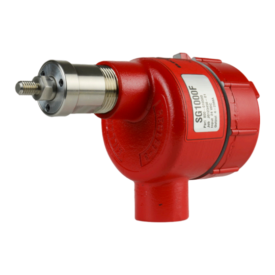
Physical Appearance and Installation Overview
Figure 1 is the front-view of the SG1000F, showing the encoder-
output-shaft.
Cable
The SG1000F attaches to the process's shaft, or similar rotating
mechanical component, using an "end-of-shaft" mounting
method. See Figure 2. The SG1000F's encoder-shaft-end
screws into a single 3/8-inch diameter hole, to a depth of 0.625
inch, having 3/8" – 16 UNC-2B threads. (Install the 3/8" split
lockwasher, apply thread locker compound, and torque to 8ft-
lbs).
Even though the SG1000F is mounted to the process shaft via
the "end-of-shaft" mounting method, installation of flexible
conduit and the stabilizer bracket is recommended, which
allows the SG1000F to "float" along with any wobble of the
process's shaft while still preventing the SG1000F from rotating
along with that shaft (see Fig. 2).
Note: The stabilizer bracket's U-bolt is slightly oversized
to provide about 1/8" of slack between it and the
SG1000F. The U-bolt's slack prevents it from
rigidly clamping to the SG1000F's conduit port.
SG1000
U-Bolt
with slack
Flexible
conduit
6111 Blue Circle Drive
Minnetonka, MN 55343
Phone: 952.930.0100
Fax: 952.930.0130
ISO 9001:2000 Certified
3/8" Split Lockwasher
(Washer Shipped with
Stabilizer Bracket Kit)
Encoder-Shaft
3/8"-16 UNC-2A threads
Figure 1:
Process Shaft
Stabilizer bracket
Structural Framework
Figure 2:
Electrical connections
The SG1000F's electrical cable has three wires, plus a shield-
wire. Connect as follows: (See Figure 3):
Red
(+)
Requires
User Installed
Class 2 Isolated
+24Vdc
-
Black
Power Supply
(
)
• Connect the shield wire to the earth ground.
• Connect the black wire to the power-supply (-) terminal.
• Connect the red wire to the power-supply (+24 Vdc)
terminal.
• Connect the clear wire to a resistive load of 250 Ω to
500 Ω, (usually this load is internal to a PLC, etc.).
Note: The clear wire is the 4-20 mA DC output line.
The other side of the 250 Ω to 500 Ω load must be
connected to the power-supply (-) terminal.
• See Figure 4 below for related information.
Calibration Procedure
Calibration consists of teaching the SG1000F the encoder values
for the fully-closed (0% open) and fully-open (100% open)
positions. The eight calibration steps are as follows (once the
user is familiar with the calibration procedure they need only
follow the underlined portions as a quick calibration guide):
1) Remove (twist CCW) the back-end-cover from the
SG1000F.
This provides access to the edge of the SG1000F's printed
circuit board, namely the direction switch SW1 (the slide
switch), and the calibration switch SW2 (the push-button
switch). See Figure 4 for locations of these switches.
CCW
SW2
R8
R7
TB1
Ground
Screw
Free Catalog and Application Assistance
SG1000
Ammeter
(optional)
+
-
Clear 4-20mA
PLC, Etc.
4-20mA
Shield
250 to 500
ohm load
Figure 3:
CW
CW(OFF)
CCW(ON)
SW1
SW1 Detail
Red
Clear
Black
Shield
Figure 4:
1.800.328.6170
Visit Us Online
www.electro-sensors.com
990-002450 Revision C
Advertisement
Table of Contents

Related Manuals for Electro-Sensors SG1000F


Summary of Contents for Electro-Sensors SG1000F
- Page 1 (programs) the SG1000F the fully-closed (0% open) and (optional) fully-open (100% open) process positions. Once programmed, the SG1000F outputs a 4 mA DC signal when the process is in the fully-closed position, and outputs a 20 mA DC signal when Clear 4-20mA the process is in the fully-open position.
- Page 2 The user normally should not have to disconnect the • The output signal remains at 12 mA. 3-wire cable from the SG1000F. But if they do so, they must reconnect the 3-wire cable to the SG1000F as 6) Move the process shaft to the fully-open position (i.e., 100% open).
- Page 3 4-20mA output signal. position, then the output signal remains at 20 mA. This is 1) If your SG1000F outputs a 4 mA to 20 mA signal, but not at known as 100% ‘run-out’, and it holds to a certain point.
- Page 4 Additional Information Resolve to 1 encoder count of calibrated span Accuracy position (span from fully closed to fully open). To get additional information about the SG1000F, visit our Varies linearly from best of 0.2% of span, website at: www.electro-sensors.com 4-20 mA to worst of 5.0% of span...
Need help?
Do you have a question about the SG1000F and is the answer not in the manual?
Questions and answers