
Related Manuals for Hammerhead 100XTR


Summary of Contents for Hammerhead 100XTR
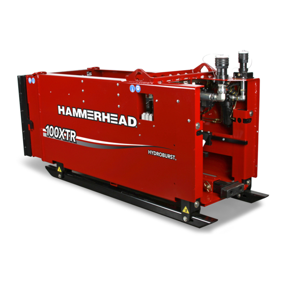
- Page 1 T E C H N I C A L P U B L I C AT I O N S Operator's Manual 100XTR Issue 2.1 960-1015 Original Instruction...
-
Page 2: Table Of Contents
100XTR Operator’s Manual Overview Chapter Contents Serial Number Location ..... . 2 Intended Use ....... 3 Equipment Modification . -
Page 3: Serial Number Location
100XTR Operator’s Manual Serial Number Location Serial Number Location Record serial numbers and date of purchase in spaces provided. j51om001w21.eps Date of manufacture Date of purchase 2 - Overview... -
Page 4: Intended Use
4” (10.2 cm) to 16” (40.6 cm) diameter buried pipes and conduits. The 100XTR produces 100 tons (91 t) of pullback force. A power unit provides hydraulic power to run the pipe bursting unit. -
Page 5: Unit Components
100XTR Operator’s Manual Unit Components Unit Components j51om013w21.eps 1. Wireless remote controller 3. Extraction cage 2. Rod box 4. Bursting unit 4 - Overview... -
Page 6: Bursting Unit Components
100XTR Operator’s Manual Unit Components Bursting Unit Components j51om002w21.eps 1. Bungee 3. Push/Pull clamp 2. Push/Pull carriage 4. Spinner Overview - 5... -
Page 7: Receiver Antenna
100XTR Operator’s Manual Unit Components Receiver Antenna j51om018w21.eps IMPORTANT: Receiver antenna can stop working if damaged. If receiver antenna is damaged, replace with CMW approved components. 6 - Overview... -
Page 8: Regulatory Notices
100XTR Operator’s Manual Regulatory Notices Regulatory Notices United States This device complies with Part 15 of the FCC Rules. Operation is subject to the following conditions: (1) this device may not cause harmful interference, and (2) this device must accept any interference received, including interference that may cause undesired operation. -
Page 9: Rf Exposure Statement
100XTR Operator’s Manual Regulatory Notices RF Exposure Statement In order to comply with RF exposure requirements during normal operation, this device must be held in front of the body horizontally. The antenna must be vertical in line with the body with at least 4” (100mm) separation distance from the body. -
Page 10: Operator Orientation
100XTR Operator’s Manual Operator Orientation Operator Orientation IMPORTANT: Top view of unit is shown. 1. Front of unit 2. Right side of unit 3. Rear of unit 4. Left side of unit j51om003w21.eps Operating Area IMPORTANT: Top view of unit is shown. -
Page 11: About This Manual
100XTR Operator’s Manual About This Manual About This Manual This manual contains information for the proper use of this machine. See Operation Overview for basic operating procedures. Cross references such as “See page 50” will direct you to detailed procedures. -
Page 12: Foreword
If you sell your equipment, be sure to give this manual to the new owner. If you need a replacement copy, contact your HammerHead dealer. If you need assistance in locating a dealer, visit our website at www.hammerheadtrenchless.com or write to the following address: HammerHead Trenchless Equipment 500 South C.P. - Page 13 Part number 960-1015 Copyright 2021, 2022 by The Charles Machine Works, Inc. HammerHead and HydroBurst are registered trademarks of The Charles Machine Works, Inc. This product and its use may be covered by one or more patents at http://patents.charlesmachine.works. 12 - Foreword...
- Page 14 100XTR Operator’s Manual Contents Overview machine serial number, information about the type of work this machine is designed to perform, basic machine components, and how to use this manual Foreword part number, revision level, and publication date of this manual, and factory contact...
- Page 15 100XTR Operator’s Manual Support the warranty policy for this machine, and procedures for obtaining warranty consideration and training Service Record a record of major service performed on the machine 14 - Contents...
-
Page 16: Safety
100XTR Operator’s Manual Safety Chapter Contents Safety Alert Classification ....16 Guidelines ....... . 17 Grounding Instructions . -
Page 17: Safety Alert Classification
100XTR Operator’s Manual Safety Alert Classifications Safety Alert Classifications These classifications and the icons defined on the following pages work together to alert you to situations which could be harmful to you, jobsite bystanders or your equipment. When you see these words and icons in the book or on the machine, carefully read and follow all instructions. -
Page 18: Guidelines
• Fully inspect equipment before operating. Repair or replace any worn or damaged parts. Replace missing or damaged safety shields, safety signs, and decals. Contact your HammerHead dealer for assistance. • Use equipment carefully. Stop operation and investigate anything that does not look or feel right. - Page 19 100XTR Operator’s Manual Guidelines • Do not unplug by pulling on cord. To unplug, grasp the plug, not the cord. • Unplug from outlet when not in use and before servicing or cleaning. • For a grounded appliance, connect to a properly grounded outlet only. See grounding instructions.
-
Page 20: Grounding Instructions
100XTR Operator’s Manual Grounding Instructions Grounding Instructions Electric shock. Improper connection of equipment- grounding conductor will cause death or serious injury. Contact qualified electrician to ensure outlet is properly grounded. To help avoid injury: • Never modify plug provided with product. If plug will not fit outlet, have a proper outlet installed by a qualified electrician. -
Page 21: Emergency Procedures
100XTR Operator’s Manual Emergency Procedures Emergency Procedures Jobsite hazards could cause death or serious injury. Use correct equipment and work methods. Use and maintain proper safety equipment. Before operating any equipment, review emergency procedures and check that all safety precautions have been taken. -
Page 22: If A Gas Line Is Damaged
100XTR Operator’s Manual Emergency Procedures • DO NOT TOUCH ANYTHING. • Remain in pit. • Warn people nearby that an electric strike has occurred. Instruct them to leave the area and contact utility. • Contact utility company to shut off power. - Page 23 100XTR Operator’s Manual Emergency Procedures • If fire is small and fire extinguisher is available, attempt to extinguish fire. • If fire cannot be extinguished, leave area as quickly as possible and contact emergency personnel. 22 - Safety...
-
Page 24: Machine Safety Alerts
100XTR Operator’s Manual Machine Safety Alerts Machine Safety Alerts Lift point. See Transport chapter for more information. Tiedown location. See Transport chapter for more information. Moving parts could crush hand. Stay away. Misuse of machine can cause death or serious injury. - Page 25 100XTR Operator’s Manual Machine Safety Alerts Hot parts may cause burns. Do not touch until cool or wear gloves. Flying objects thrown by machine may strike people. Wear safety glasses and hard hat. Crushing weight could kill or seriously injure. Stay away.
-
Page 26: Controls
100XTR Operator’s Manual Controls Chapter Contents Bursting Unit ........26 •... - Page 27 100XTR Operator’s Manual Bursting Unit Bursting Unit Manual Controls j51om005w21.eps IMPORTANT: Manual controls are used as a backup in the event the remote becomes inoperable. See “Setup and Configuration” on page 56. 1. Bungee clamp control 4. Push/Pull clamp control 2.
- Page 28 100XTR Operator’s Manual Bursting Unit Item Description Notes 1. Bungee switch control To open bungee clamp, pull up. To close bungee clamp, push down. c00ic414w.eps 2. Spinner clamp control To close spinner clamp, press down. c00ic415w.eps 3. Spinner control To rotate spinner clockwise (makeup), pull up.
- Page 29 100XTR Operator’s Manual Bursting Unit Stabilizer Controls NOTICE: Raising one side of bursting unit too much can cause the unit to tip over. 1. Left stabilizer control 3. Rear stabilizer control 2. Right stabilizer control Item Description Notes 1. Left stabilizer control To raise, pull back.
- Page 30 100XTR Operator’s Manual Bursting Unit Item Description Notes 2. Right stabilizer control To raise, pull back. To lower, push forward. 3. Rear stabilizer control To raise, pull back. To lower, push forward. Controls - 29...
- Page 31 100XTR Operator’s Manual Bursting Unit Miscellaneous Controls j51om006w21.eps Item Description Notes Auxiliary outlet Provides power for other Power output is fused to 15A equipment. 30 - Controls...
- Page 32 100XTR Operator’s Manual Bursting Unit Miscellaneous Controls j51om017w21.eps Item Description Notes Remote engine stop switch To stop engine, press. Engine will not start until control is returned to neutral position. c00ic683w.eps Controls - 31...
- Page 33 100XTR Operator’s Manual Wireless Remote Controller Wireless Remote Controller j59om001w20.eps 1. LCD display 8. Power status indicator 2. Mode select 9. Power/Horn/Start/Set 3. Throttle hi/low 10. Push/Pullback control joystick, extend/retract clamp switch 4. Spinner control switch/Bungee clamp switch. - 11. Pullback force switch 5.
- Page 34 100XTR Operator’s Manual Wireless Remote Controller Item Description Notes 2. Mode select To cycle through operating Auto, manual, limit setting. settings, press up/down. Operation is only valid if Tx-Rx communication link is active. c00ic399w.eps 3. Throttle hi/low To activate throttle (hi), move Operate machine at high throttle.
- Page 35 100XTR Operator’s Manual Wireless Remote Controller Item Description Notes 6. Stop Button To activate the stop output, Activating the stop output resets control press button. outputs to off state Activating the stop output cancels the start ready condition. Stop output will automatically turn off in about two seconds after the stop button is released.
- Page 36 100XTR Operator’s Manual Wireless Remote Controller Item Description Notes 10. Push/Pullback control To retract cylinder, move joystick Joystick/switch operation requires start joystick, extend/retract ready condition and an active operator clamp switch (manual presence switch. mode) To extend cylinder, move joystick down.
- Page 37 100XTR Operator’s Manual Wireless Remote Controller Item Description Notes Auto power off Unit will automatically power off after 60 seconds since the last switch input or joystick movement is detected and the accelerometer input is stale. Unit will automatically power off...
-
Page 38: Prepare
100XTR Operator’s Manual Prepare Chapter Contents Gather Information ......38 • Review Job Plan ......... . .38 •... -
Page 39: Gather Information
100XTR Operator’s Manual Gather Information Gather Information A successful job begins before the pull. The first step in planning is reviewing information already available about the job and jobsite. Review Job Plan Review blueprints or other plans and make sure you have taken enlargement during pullback into account. -
Page 40: Inspect Site
100XTR Operator’s Manual Inspect Site Inspect Site Identify Hazards Entering a confined space without following all required procedures and having and effective emergency rescue plan can result in serious injury or death. To help avoid injury: • Follow local regulations for confined space. -
Page 41: Select Installation And Bursting Pit Locations
100XTR Operator’s Manual Inspect Site Select Installation and Bursting Pit Locations Consider the following when selecting pit locations: Slope Consider how slope will affect unit setup and operation. Assess the risks on each slope to determine if factors affecting the risks create an unsafe condition for pipe bursting. -
Page 42: Classify Jobsite
100XTR Operator’s Manual Classify Jobsite Classify Jobsite Jobsite hazards could cause death or serious injury. Use correct equipment and work methods. Use and maintain proper safety equipment. To help avoid injury: • Wear personal protective equipment including hard hat, safety eye wear, and hearing protection. -
Page 43: Apply Precautions
100XTR Operator’s Manual Classify Jobsite Apply Precautions Once classified, precautions appropriate for jobsite must be taken. Follow U.S. Department of Labor regulations on excavating and trenching (Part 1926, Subpart P) and other similar regulations. Electric Jobsite Precautions Electric shock will cause death or serious injury. Stay away. -
Page 44: Plan Pull Path
100XTR Operator’s Manual Plan Pull Path Crystalline Silica (Quartz) Dust Precautions Breathing crystalline silica dust may cause lung disease. Cutting, drilling, or working materials such as concrete, sand, or rock containing quartz may result in exposure to silica dust. Use dust control methods or appropriate breathing protection when exposed to silica dust. -
Page 45: Prepare Jobsite
100XTR Operator’s Manual Prepare Jobsite Prepare Jobsite Jobsite hazards could cause death or serious injury. Use correct equipment and work methods. Use and maintain proper safety equipment. To help avoid injury: • If jobsite classification is in question or the possibility of unmarked electric utilities exists, classify jobsite as electric. - Page 46 100XTR Operator’s Manual Prepare Jobsite Dig Bursting Pit Dimensions j51om030w.eps Minimum Bursting Pit Length (A) Width (B) Depth (C) U.S. (metric) U.S. (metric) U.S. (metric) 110” (2.8 m)* 48” (1.2 m) 18” (0.5 m)** *Add 73.5” (1.9 m) of length of bursting pit if using the extraction cage.
- Page 47 100XTR Operator’s Manual Prepare Jobsite Requirements Installation Pit (1) • Pit dimensions depend on pipe depth and product being installed. • Must be in line with existing pipe. • Sloped back end aids new product installation. Consider new product bend radius.
-
Page 48: Check Supplies And Prepare Equipment
100XTR Operator’s Manual Check Supplies and Prepare Equipment Check Supplies and Prepare Equipment Check Supplies • marking flags or paint • fuel • hydraulic oil • keys • cutting heads, clevis • barrier cones and tape • rod joint lube antiseize MIL-A-907E •... - Page 49 100XTR Operator’s Manual Check Supplies and Prepare Equipment 48 - Prepare...
-
Page 50: Transport
100XTR Operator’s Manual Transport Chapter Contents Lift ........50 •... -
Page 51: Lift
100XTR Operator’s Manual Lift Lift Crushing weight could cause death or serious injury. Stay away. Points Lifting points are identified by lifting decals. Lifting at other points is unsafe and can damage machinery. Procedure Bursting Unit Use equipment capable of supporting the unit's size and weight. - Page 52 100XTR Operator’s Manual Lift Extraction Cage Use equipment capable of supporting the extraction cage's size and weight. See “Extraction Cage” on page 96. Rod Box Use equipment capable of supporting the rod box's size and weight. j51om034w.eps Transport - 51...
-
Page 53: Tie Down
100XTR Operator’s Manual Tie Down Tie Down Points Tiedown points are identified by tiedown decals. Securing to trailer at other points can damage machinery. Procedure Bursting Unit To tie down bursting unit, use D-rings shown. NOTICE: Do not attempt to transport rod box with bursting unit. - Page 54 100XTR Operator’s Manual Tie Down Rod Box To tie down rod box use D-rings shown. j51om035w.eps Transport - 53...
- Page 55 100XTR Operator’s Manual Tie Down 54 - Transport...
-
Page 56: Burst Pipe
100XTR Operator’s Manual Burst Pipe Chapter Contents Setup and Configuration ....58 Emergency Stop Procedure....61 Open/Close Bungee . -
Page 57: Setup And Configuration
100XTR Operator’s Manual Setup and Configuration Setup and Configuration j51om007w21.eps 1. Bursting unit Hydraulic connection hoses Power unit Rod box Extraction cage Wireless Remote Controller NOTICE: Follow U.S. Department of Labor regulations on excavating and trenching (Part 1926, Subpart P) and other similar regulations. - Page 58 100XTR Operator’s Manual Setup and Configuration 1. Use equipment capable of safely lifting and unloading power unit, bursting unit, extraction cage, and related equipment next to bursting pit. 2. Set power unit switch to OFF. 3. Position power unit outside of bursting pit, at least two feet away from the edge.
- Page 59 100XTR Operator’s Manual Setup and Configuration Pressurized fluid or air could pierce skin and cause severe injury. Refer to operator’s manual for proper use. To help avoid injury: • Always connect return line first and remove last. • Before using system, check that all connections are tight and all lines are undamaged.
-
Page 60: Emergency Stop Procedure
100XTR Operator’s Manual Emergency Stop Procedure Emergency Stop Procedure To shut down power unit engine under normal conditions, use key switch or emergency stop on power unit. To shut down power unit using wireless remote controller, press the remote stop switch on wireless remote controller. -
Page 61: Open Bungee
100XTR Operator’s Manual Open/Close Bungee Open Bungee In manual mode, when bungee clamp is open, rod will move freely in either direction. Use wireless remote controller to open bungee clamp. j51om008w21.eps 62 - Burst Pipe... -
Page 62: Push Rods
100XTR Operator’s Manual Push Rods . Push Rods Misuse of machine can cause death or serious injury. Read and understand operator’s manual and all other safety instructions before use. To help avoid injury: • Maintain 2-way communication between bursting pit and all other personnel. - Page 63 100XTR Operator’s Manual Push Rods . 8. Install push point on end of pilot rod. 9. Insert rod into bursting unit through open clamp until joint is visible in window (shown). 10. Close clamp. 11. Install rod. 12. To connect rods, rotate spinner clockwise.
-
Page 64: Connect Tooling String To Pilot Rod
100XTR Operator’s Manual Connect Tooling String to Pilot Rod Connect Tooling String to Pilot Rod Misuse of machine can cause death or serious injury. Read and understand operator’s manual and all other safety instructions before use. To help avoid injury: •... -
Page 65: Pull Back Rods
100XTR Operator’s Manual Pull Back Rods Pull Back Rods Misuse of machine can cause death or serious injury. Read and understand operator’s manual and all other safety instructions before use. To help avoid injury: • Maintain 2-way communication between bursting pit and all other personnel. - Page 66 100XTR Operator’s Manual Pull Back Rods 1. Place at least one operator/pipe loader in the bursting pit. Keep this person at rear of unit in operating area (page 9). 2. Start power unit engine. Set engine to high throttle. NOTICE: To shut down power unit when using remote controller, press the remote stop switch on remote controller.
-
Page 67: Pull New Product
100XTR Operator’s Manual Pull New Product Pull New Product Misuse of machine can cause death or serious injury. Read and understand operator’s manual and all other safety instructions before use. To help avoid injury: • Maintain 2-way communication between bursting pit and all other personnel. - Page 68 100XTR Operator’s Manual Pull New Product 2. Continue pulling back rod string until bursting/splitting assembly reaches pit. 3. Connect one rod onto rod in bursting unit. 4. If not already in place, move bursting unit back in pit and position extraction cage between bursting unit and existing pipe and pit wall.
- Page 69 100XTR Operator’s Manual Pull New Product 70 - Burst Pipe...
-
Page 70: Troubleshooting
100XTR Operator’s Manual Troubleshooting Chapter Contents Display Does Not Turn On ....72 No Connection to Down Hole Unit ... . 73 Tooling Stuck in Pipe/Ground . - Page 71 100XTR Operator’s Manual Display Does Not Turn On Display Does Not Turn On 1. Check battery levels in wireless remote control. 2. Change batteries if needed. 3. If replacement batteries are not available, connect battery back-up cable to remote. 4. Contact dealer for further assistance.
- Page 72 100XTR Operator’s Manual No Connection to Down Hole Unit No Connection to Down Hole Unit If communication link indicator is flashing yellow, communication between wireless remote control and machine has stopped. Move wireless remote control closer to machine while maintaining a safe distance.
- Page 73 100XTR Operator’s Manual Tooling Stuck in Pipe/Ground Tooling Stuck in Pipe/Ground If down hole unit tonnage reaches 100ton and rod/tooling does not move, tool string may need to be excavated. 1. Unload and release bungee to relieve all tension on rod.
-
Page 74: Systems And Equipment
100XTR Operator’s Manual Systems and Equipment Chapter Contents Tooling String ......76 •... -
Page 75: Tooling String
100XTR Operator’s Manual Tooling String Tooling String Bursting String Ref. Description pipe pilot flex joint expander expander rod assembly pipe puller j51om006w.eps Slitter String Ref. Description flex joint slitter assembly trailing pivot rod assembly expander expander rod assembly pipe puller j51om007w.eps... -
Page 76: Bursting/Splitting Heads
100XTR Operator’s Manual Extraction Cage Bursting/Splitting Heads Identification and Uses Ref. Type Uses slitter ductile iron, steel, cast iron with repairs pipe pilot clay, asbestos cement, PVC, PE, cast iron j51om008w.eps Extraction Cage The extraction cage allows room to remove the bursting/splitting assembly from the new product after it enters the bursting pit. - Page 77 100XTR Operator’s Manual Extraction Cage 78 - Systems and Equipment...
-
Page 78: Complete The Job
100XTR Operator’s Manual Complete the Job Chapter Contents Disconnect Hoses......80 Stow Components ......81 Restore Jobsite . - Page 79 100XTR Operator’s Manual Disconnect Hoses Disconnect Hoses Pressurized fluid or air could pierce skin and cause severe injury. Refer to operator’s manual for proper use. To help avoid injury: • Always connect return line first and remove last. • Before using system, check that all connections are tight and all lines are undamaged.
- Page 80 100XTR Operator’s Manual Stow Components Stow Components 1. Install all covers. 2. Load components onto trailer. 3. Secure all components on trailer. Restore Jobsite Fill in installation, bursting and service connection pits. Stow Tools Make sure all accessories and tools are loaded and properly secured on trailer.
- Page 81 100XTR Operator’s Manual Decommission Machine 82 - Complete the Job...
-
Page 82: Service
100XTR Operator’s Manual Service Chapter Contents Service Precautions ......82 • Remove/Install Front Panel........82 Recommended Lubricants/Service Key . -
Page 83: Service Precautions
100XTR Operator’s Manual Service Precautions Service Precautions Misuse of machine can cause death or serious injury. Read and understand operator’s manual and all other safety instructions before use. 273-475 To help avoid injury: • Unless otherwise instructed, all service should be performed with engine off. -
Page 84: Recommended Lubricants/Service Key
In extreme conditions, service machine more frequently. Use only recommended lubricants. NOTICE: • Use only genuine HammerHead parts and approved lubricants to maintain warranty. • Use the “Service Record” on page 101 to record all required service to your machine. Service - 83... -
Page 85: Each Use
100XTR Operator’s Manual Each Use Each Use Tasks Notes Inspect rods/pipes after each use Clean jaw after each use Clean rod wipers after each use Inspect Rods/Pipes Inspect rods/pipes after each use. Ensure rods/pipes are not: • severely bent •... - Page 86 100XTR Operator’s Manual Each Use Clean Rod Wiper IMPORTANT: Replace rod wiper if damaged or worn. Clean rod wiper with high-pressure water after each use. j51om004w19.eps Service - 85...
-
Page 87: 50 Hour
100XTR Operator’s Manual 50 Hour 50 Hour Task Notes Check hydraulic hoses Change hydraulic pressure filter initial change Check Hydraulic Hoses Pressurized fluid or air could pierce skin and cause severe injury. Refer to operator’s manual for proper use. To help avoid injury: •... - Page 88 100XTR Operator’s Manual 50 Hour Change Hydraulic Pressure Filter (initial) Change hydraulic pressure filter after 50 hours initially, and every 200 hours thereafter. j51om001w.eps Service - 87...
- Page 89 100XTR Operator’s Manual 200 Hour 200 Hour Task Notes Change hydraulic pressure filter Change Hydraulic Pressure Filter Change hydraulic pressure filter every 200 hours. j51om001w.eps 88 - Service...
-
Page 90: As Needed
100XTR Operator’s Manual As Needed As Needed Task Notes Replace jaws carriage and bungee Replace spinner and carriage guides Replace rod wiper Replace carriage wheels Lube rod/pipe threads Lube bowls bungee vise and carriage vise, EPRG Clean and lube spinner... - Page 91 100XTR Operator’s Manual As Needed Push/Pull 1. Extend push/pull cylinders to end of travel. 2. Remove snap ring and rod guide. 3. Remove pin (1) from slip (2). 4. Remove remove jaw insert (3). 5. Install replacement jaw insert. 6. Reinstall pin.
- Page 92 100XTR Operator’s Manual As Needed Lube Rod/Pipe Threads Lube with RJL antiseize lubricant as needed. NOTICE: • Apply lubricant to female threads only. • If rod/pipe threads are damaged, replace immediately. • Ensure rods/pipes are free from any dirt or debris.
- Page 93 100XTR Operator’s Manual As Needed Lube Bowls Lube bowls as needed. Bungee Vise 1. Remove front plate. 2. Remove rod wiper. 3. Remove rod guide. 4. Apply five pumps of EPRG to each grease zerk (shown) on each slip. j51om010w21.eps Carriage Vise 1.
- Page 94 100XTR Operator’s Manual As Needed Clean and Lube Spinner 1. Remove disengagement flange (2), flex-top lock nut (1), and spinner jaw. 2. Remove all debris from around dovetail ramp (4). 3. Remove any scale, rust, or build up from: •...
- Page 95 100XTR Operator’s Manual As Needed 94 - Service...
-
Page 96: Specifications
100XTR Operator’s Manual Specifications Bursting Unit Dimensions U.S. Metric L, length 83 in 2.1 m W, width 30 in 762 mm H, height 39 in 990 mm H2, rod height 18 in 457 mm Weight, mass 3200 lb 1452 kg Operational U.S. - Page 97 100XTR Operator’s Manual Extraction Cage Extraction Cage Dimensions U.S. Metric L, length 73.5 in 1.9 m W, width 34 in 864 mm H, height 34 in 864 mm Weight, mass 1045 lb 474 kg 96 - Specifications...
- Page 98 100XTR Operator’s Manual Wireless Remote Controller Wireless Remote Controller Dimensions U.S. Metric L, length 9.0 in 22.9 cm W, width 7.9 in 20.1 cm H, height 4.75 in 12.1 cm Weight, mass 2.6 lb 1.2 kg Environmental U.S. Metric Operating temperature -4 to 158°F...
- Page 99 100XTR Operator’s Manual Declaration of Conformity Information Declaration of Conformity Information Countries in the European Union should have received a Declaration of Conformity (DOC) with this machine similar to the example below. Earth Tool Company, LLC. 500 South C.P. Avenue...
- Page 100 Return damaged parts to dealer for inspection and warranty consideration if in warranty time frame. Order genuine HammerHead replacement or repair parts from your authorized HammerHead dealer. Use of another manufacturer's parts may void warranty consideration.
- Page 101 Dealer shall furnish parts without charge for any HammerHead product that fails because of defects in material and workmanship. Warranty is void unless warranty registration card is returned within ten days from the date of purchase. This warranty and any...
- Page 102 100XTR Operator’s Manual Service Record Service Performed Date Hours Service Record - 101...
- Page 103 100XTR Operator’s Manual Service Performed Date Hours 102 - Service Record...
Need help?
Do you have a question about the 100XTR and is the answer not in the manual?
Questions and answers