Table of Contents
Advertisement
Quick Links
Trademarks
Autel
®
and MaxiIM
Corp., Ltd., registered in China, the United States and other countries. All
other marks are trademarks or registered trademarks of their respective
holders.
Copyright Information
No part of this manual may be reproduced, stored in a retrieval system or
transmitted, in any form or by any means, electronic, mechanical,
photocopying, recording, or otherwise without the prior written permission of
Autel.
Disclaimer of Warranties and Limitation of Liabilities
All information, specifications and illustrations in this manual are based on
the latest information available at the time of printing.
Autel reserves the right to make changes at any time without notice. While
information of this manual has been carefully checked for accuracy, no
guarantee is given for the completeness and correctness of the contents,
including but not limited to the product specifications, functions, and
illustrations.
Autel will not be liable for any direct, special, incidental, indirect damages or
any economic consequential damages (including the loss of profits).
IMPORTANT
Before operating or maintaining this unit, please read this manual carefully,
paying extra attention to the safety warnings and precautions.
For Services and Support
www.autel.com
support@autel.com
For technical assistance in all other markets, please contact your local
selling agent.
are trademarks of Autel Intelligent Technology
®
i
Advertisement
Table of Contents

Related Manuals for Autel MaxiIM IM508


Summary of Contents for Autel MaxiIM IM508
- Page 1 All information, specifications and illustrations in this manual are based on the latest information available at the time of printing. Autel reserves the right to make changes at any time without notice. While information of this manual has been carefully checked for accuracy, no...
- Page 2 Safety Information For your own safety and the safety of others, and to prevent damage to the device and vehicles upon which it is used, it is important that the safety instructions presented throughout this manual be read and understood by all persons operating or coming into contact with the device.
- Page 3 Safety Instructions The safety messages herein cover situations Autel is aware of. Autel cannot know, evaluate or advise you as to all of the possible hazards. You must be certain that any condition or service procedure encountered does not jeopardize your personal safety.
- Page 4 time. Any distraction may cause an accident. Refer to the service manual for the vehicle being serviced and adhere to all diagnostic procedures and precautions. Failure to do so may result in personal injury or damage to the test equipment. To avoid damaging the test equipment or generating false data, make ...
-
Page 5: Table Of Contents
CONTENTS 1 USING THIS MANUAL................... 1 ......................1 ONVENTIONS 2 GENERAL INTRODUCTION................. 3 IM IM508 D ................4 ISPLAY ABLET XP200........................8 3 GETTING STARTED.................... 19 ......................19 OWERING ....................22 OWERING 4 IMMO........................24 ....................24 ETTING TARTED ..................25 EHICLE DENTIFICATION ......................28 AVIGATION IMMO........................32 5 PROGRAMMING....................39 ...................... - Page 6 ....................... 93 ANGUAGE ....................93 RINTING ETTING ....................94 IRMWARE PGRADE ....................94 OTIFICATION ENTER ....................... 95 ULTITASK ......................95 PDATE ....................96 YSTEM ETTINGS ........................97 BOUT 10 REMOTE DESK.....................98 11 DATA MANAGER....................100 ......................100 PERATIONS 12 SHOP MANAGER....................105 ....................106 EHICLE ISTORY ..................109...
-
Page 7: Using This Manual
Using this Manual This manual contains device usage instructions. Some illustrations shown in this manual may contain modules and optional equipment that are not included in your system. Conventions The following conventions are used. Bold Text Bold text is used to highlight selectable items such as buttons and menu options. - Page 8 Example: IMPORTANT Keep the cable away from heat, oil, sharp edges and moving parts. Replace damaged cables immediately. Hyperlink Hyperlinks, or links, that take you to other related articles, procedures, and illustrations are available in electronic documents. Blue italic text indicates a selectable hyperlink and blue underlined text indicates a website link or an email address link.
-
Page 9: General Introduction
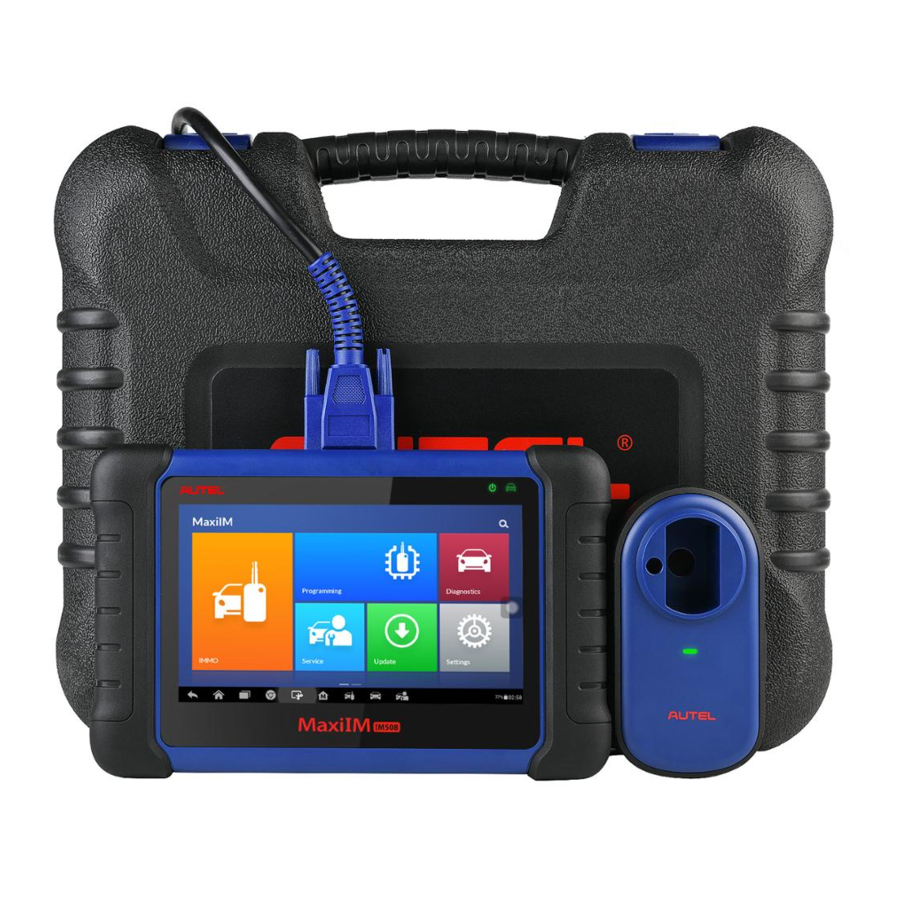
General Introduction When it comes to ultra-portability, MaxiIM IM508 is your perfect companion. Installed with a fast quad-core processor, IM508 offers maximum convenience and swift diagnosis. The intuitive user screen makes using the device effortless through a 7-inch LCD touchscreen that displays at 1024 x 600 quality. -
Page 10: Maxiim Im508 Display Tablet
MaxiIM IM508 Display Tablet Functional Description Figure 2- 1 Display Tablet Front View 7.0” LCD Capacitive Touchscreen Ambient Light Sensor – detects ambient brightness. Power LED – indicates battery level & charging or system status. Vehicle Communication LED – flashes green when the Display Tablet is communicating/linking with the vehicle’s system. - Page 11 Illuminates red when the Display Tablet is powered on and the battery level is below 15%. Figure 2- 2 Display Tablet Back View Collapsible Stand – extends from the back to allow hands-free viewing of the Display Tablet. Heat Sink Built-in Battery Figure 2- 3 Display Tablet Top View Mini USB OTG Port...
- Page 12 Internal Battery Pack External Power Supply Internal Battery Pack The Display Tablet can be powered with the internal rechargeable battery, which if fully charged can provide sufficient power for about 4.5 hours of continuous operation. Vehicle Power When the Display Tablet is connected to the test vehicle via the main cable, the Display Tablet automatically receives power from the vehicle.
- Page 13 Item Description Input: N/A Audio Input/Output Output: buzzer 3.7 V/5000 lithium-polymer battery Power and Battery Charges via 5 VDC power supply Tested Battery Life Around 4.5 hours of continuous use Battery Charging 5 V/1.5 A Input 500 mA (LCD on with default brightness, Power Consumption Wi-Fi on) @3.7 V...
-
Page 14: Xp200
connector (DLC). Figure 2-4 Main Cable Other Accessories Suitable for Mazda-17 Adaptor Suitable for KIA-10 Adaptor Suitable for KIA-20 Adaptor Suitable for Honda-3 Adaptor AAC001 – MED17 Cable Mini USB Cable Connects the Display Tablet to the PC or DC external power adapter. - Page 15 that are both loaded with programmer software, the XP200 can read/write key chip data quickly and accurately. Specifications Table 2- 2 Specifications Item Description Operating Temperature -10℃ ~ 50℃ (14℉ ~ 122℉) Storage Temperature -20℃ ~ 60℃ (-4℉ ~ 140℉) Port Mini USB, VGA_DB15 Input Voltage...
- Page 16 APA002 – EEPROM Socket APA001 – EEPROM Clamp Integrated MC9S12 Cable Components and Ports Figure 2- 4 XP200 Views Vehicle Key Chip Slot – holds the vehicle key chip. Vehicle Key Slot – holds the vehicle key. Status LED Light – indicates the current operating status. Connection Port –...
- Page 17 Vehicle Key Chip Slot Holds the Vehicle Key Chip to read and write vehicle key chip information. Status LED Light The status LED of the XP200 indicates the operating status of the device. for detailed description. Table 2- 3 Table 2- 3 Status LED Light on the Front Panel LED Light Color/Status Description...
- Page 18 Figure 2- 5 EEPROM Clamp Integrated MC9S12 Cable MC9S12 Cable Table 2- 4 Definitions of MC9S12 Cable correspond Color Definition Note to DB15 Green TXCLKS Black Shielded line White TOSC Shielded line Blue Brown Yellow TRESET...
- Page 19 EEPROM Clamp Cable Table 2- 5 Definitions of EEPROM Clamp Cable Color Definition correspond Note to DB15 Pin 1 is White and Red White and Purple White and Blue Grey White and Brown...
- Page 20 White and Green White and Orange Pin 8 is White and Black black Here are the possible causes for EEPROM read/write failure and data error when connecting the clamp to the test board for EEPROM read/write: A. EEPROM read/write operations are affected by the circuit of the connected test board;...
- Page 21 EEPROM Read/Write Supported Types Chip Type Name Chip Type Name ATMEL AT24C01 M24C04 ATMEL AT24C02 M24C08 ATMEL AT24C04 M24C16 ATMEL AT24C08 M24C32 ATMEL AT24C16 M24C64 ATMEL AT24C32 FAIRCHILD NM24C16U ATMEL AT24C64 FAIRCHILD NM24C16UT ATMEL AT24C128 FAIRCHILD NM24C17U ATMEL AT24C256 FAIRCHILD NM24C17UT ATMEL AT24C512...
- Page 22 Chip Type Name Chip Type Name ATMEL AT25256 MICROCHIP 25xx160 ATMEL AT25512 MICROCHIP 25xx320 ATMEL AT25010_1.8 MICROCHIP 25xx640 ATMEL AT25020_1.8 MICROCHIP 25xx040_TSSOP ATMEL AT25040_1.8 MICROCHIP 25xx320_TSSOP ATMEL AT25080_1.8 MICROCHIP 25xx640_TSSOP ATMEL AT25160_1.8 CATALYST CAT25C01 ATMEL AT25320_1.8 CATALYST CAT25C02 ATMEL AT25640_1.8 CATALYST CAT25C04 ATMEL...
- Page 23 Chip Type Name Chip Type Name MICROCHIP 93C46X NATIONAL NM93CS56 MICROCHIP 93C46A NATIONAL NM93CS66 MICROCHIP 93C46 FAIRCHILD FM93CS46T MICROCHIP 93C46AX M93C46 MICROCHIP 93C46BX_93C46CX M93C56 MICROCHIP 93C56A M93C66 MICROCHIP 93C56 M93C76 MICROCHIP 93C66A M93C86 MICROCHIP 93C66 M93S46 MICROCHIP 93C76A M93S56 MICROCHIP 93C76 M93S66 MICROCHIP...
- Page 24 Chip Type Name Chip Type Name Seiko S_24H30_SOP8 TOSHIBA TC89121 Seiko S_24H45 TOSHIBA TC89122 Seiko S_24H45_SOP8 Xicor X24C44 Seiko S_24S30 9S12 Read/Write Supported Types Chip Type Name FREESCALE MC9S12DG128...
-
Page 25: Getting Started
Getting Started Ensure the tablet is sufficiently charged or is connected to the external power supply (see on page 5). Power Sources NOTE The images and illustrations depicted in this manual may differ from the actual ones. Powering Up Long press the Lock/Power button on the top right of the tablet to power on the unit. - Page 26 NOTE The tablet screen is locked by default when first powered on. It is recommended to lock the screen to protect the information in the system and reduce the power consumption. The touch screen navigation is menu driven enabling quick access to functions and features by tapping on options headings and answering dialog windows.
- Page 27 Button Name Description Accesses the organization system for saved Data Manager data files. See Data Manager Operations page 100. Accesses the Shop Manager program. See Shop Manager on page 89. Shop Manager Operations Locator and Navigation Buttons Operations of the Navigation buttons at the bottom of the screen are described in the table below: Table 3- 2 Locator and Navigation Buttons Button...
-
Page 28: Powering Down
Button Name Description Service Return to the Service screen. Shortcut System Status Icons As the Display Tablet is working with the Android operating system, you may refer to Android documents for more information. By up sliding the bottom right corner, a Shortcuts Panel will be displayed, on which you are allowed to set various system settings of the tablet. - Page 29 To power down the display tablet Long press the Lock/Power Button. Tap Power off option. Tap OK, the tablet will turn off in a few seconds. Reboot System In case of system crash, long press the Lock/Power button and tap Reboot option to reboot the system.
-
Page 30: Immo
IMMO The IMMO application provides Smart Mode and Expert Mode to guide technicians performing IMMO related functions, including Key Learning, Remote Control Learning, Remote Control Add, etc. Getting Started Ensure a communication link is established between the test vehicle and the tablet via the main cable, and the XP200 is connected to the tablet with the supplied USB cable. -
Page 31: Vehicle Identification
Top Toolbar Buttons The operations of the toolbar buttons at the top of the screen are listed and described in the table below: Table 4- 1 Top Toolbar Buttons Button Name Description Home Return to the MaxiIM Job Menu. Display a dropdown list; tap Auto Detect for auto VIN detection;... - Page 32 Auto VIN Scan Manual VIN Input Automatic Selection Manual Selection Auto VIN Scan and Manual VIN Input functions are applicable for IMMO, Diagnostic and Service applications, Automatic Selection and Manual Selection are applicable for Diagnostic and Service applications. In IMMO, except Auto VIN Scan and Manual VIN Input methods, technicians can also manually select vehicle manufacturer, instrument information step by step to locate the desired IMMO part, but it is a little different from Automatic...
- Page 33 list. Select Auto Detect. Once the test vehicle is successfully identified, the screen will display the vehicle profile. Tap OK at the bottom right to confirm the vehicle profile. If the VIN does not match with the test vehicle’s VIN, enter VIN manually or tap Read to acquire VIN again.
-
Page 34: Navigation
Tap the Diagnostic application button from the MaxiIM Job Menu. The Vehicle Menu displays. Tap the manufacturer button of the test vehicle. Tap Automatic Selection and the VIN information will be automatically acquired. Follow the on-screen instruction to display the function screen. Manual Selection When the vehicle’s VIN is not automatically retrievable through the vehicle's ECU, or the specific VIN is unknown, the vehicle can be manually selected. - Page 35 IMMO Screen Layout Figure 4- 4 Sample Mode Selection Screen The IMMO screens typically include four sections. Operation Toolbar Status Information Bar Main Section Functional Buttons Operation Toolbar The Operation Toolbar contains a number of buttons such as print and save. The table below provides a brief description of the operations.
- Page 36 Button Name Description Print a copy of the displayed data. See Printing Print for additional information on page 93. Setting Help Display operational instructions or tips. Tap to open a sub menu, tap Save This Page to take a screenshot. Save All saved data is stored in the Data Manager application for later reviews.
- Page 37 Tap the Data Logging button again to end recording. A submission form will display for inputting of report information. Tap the Send button to submit the report form via the Internet. A confirmation message displays when the report has been successfully sent.
-
Page 38: Immo
When a user-response is not required to continue, the message displays briefly. Warning Messages This type of messages displays a warning that a selected action may result in an irreversible change or loss of data. An example of this type of message is the “Erase Codes”... - Page 39 Smart Mode The Smart Mode provides guided functions with step-by-step instructions. Once the test vehicle is identified, a vehicle profile will display, select Yes to continue. Figure 4- 5 Sample Vehicle Information Screen The tablet will access the vehicle IMMO ECU to read IMMO related information.
- Page 40 Figure 4- 7 Sample Function Menu in Smart Mode The functions vary by IMMO parts, please follow the onscreen instructions to select the correct IMMO part. Take Key Learning as an example. Select Key Learning from the function menu. The tablet will automatically start to read IMMO data.
- Page 41 Figure 4- 9 Sample Key Learning Screen 2 Follow the onscreen instruction to place a Blank Key in the XP200 keyhole and press OK to continue. Figure 4- 10 Sample Key Learning Screen 3 If the new key is blocked, the tablet will ask if you want to unlock the key, select Yes to continue, or select NO to quit the operation.
- Page 42 Figure 4- 11 Sample Key Learning Screen 4 Make selections according to the test vehicle. Input the numbers of the keys to be learned and press OK to continue. Figure 4-12 Sample Key Learning Screen 5 Follow the onscreen instructions to insert the key to be learned into the vehicle ignition switch.
- Page 43 Figure 4- 13 Sample Key Learning Screen 6 10. When Key Learning is completed successfully, the following screen displays. Press OK to exit the function. Figure 4- 14 Sample Key Learning Screen 7 Expert Mode Expert Mode provides skilled technicians a convenient way to perform individual IMMO functions they need.
- Page 44 Select vehicle manufacturer in the vehicle menu, and then select the IMMO part information step by step to locate the IMMO part and display the function menu. Figure 4- 15 Sample Expert Mode Function Menu Take Read IMMO Data as an example. Select Read IMMO Data from the function menu.
-
Page 45: Programming
Programming The Programming application requires connection between the tablet and the XP200, and no vehicle connection is required. This application can access the key chip, read, retrieve and write key information, as well as other key related functions. Programming Select the vehicle manufacturer in the vehicle menu, and then follow the onscreen instructions to select the instrument information to display the function menu. - Page 46 Figure 5- 2 Sample Select Chip Type Screen Select Read Operation on the next menu. Figure 5- 3 Sample Operations Menu The chip data screen displays. Select Save to save the data, or select Cancel to exit.
- Page 47 Figure 5- 4 Sample Read Operation Screen Type the file name and select Confirm, the chip data will be saved on the tablet. And a “File saved successfully.” Message displays. Figure 5- 5 Sample Save Data Screen Select Write Operation from the operations menu. The tablet will open the default folder, select the saved data and click Confirm to write it into a black chip.
- Page 48 Figure 5- 6 Sample Write Operation Screen...
-
Page 49: Diagnostics
Diagnostics The Diagnostics application can retrieve ECU information, read & erase DTCs, and view live data. The Diagnostics application can access the electronic control unit (ECU) for various vehicle control systems, including engine, transmission, antilock brake system (ABS), airbag system (SRS). Diagnosis The Diagnostics application enables a data link to the electronic control system of the test vehicle for vehicle diagnosis via OBD II connection. - Page 50 Auto Scan The Auto Scan function performs a comprehensive scanning over all the ECUs in the vehicle to locate systems’ faults and retrieve DTCs. An example of the Auto Scan interface is pictured below: Figure 6- 1 Sample Auto Scan Operation Screen Navigation Bar Main Section Functional Buttons...
- Page 51 Display Tablet cannot accurately locate it. Fault(s) | #: Fault(s) indicates there is/are detected fault code(s) present; “#” indicates the number of the detected faults. Pass | No Fault: Indicates the system has passed the scanning process and no fault has been detected. Column 4 –...
- Page 52 Figure 6- 2 Sample Function Menu The Function Menu options vary slightly for different vehicles. The function menu may include: ECU Information – provides the retrieved ECU information in detail. An information screen opens upon selection. Read Codes – displays detailed information of DTC records retrieved ...
- Page 53 Select the desired diagnostic function from the Function Menu. ECU Information This function retrieves and displays the specific information for the tested control unit, including unit type, version numbers and other specifications. The sample ECU Information screen displays as below: Figure 6- 3 Sample ECU Information Screen Diagnostics Toolbar Buttons –...
- Page 54 Figure 6- 4 Sample Read Codes Screen Diagnostics Toolbar Buttons – see Table 4- 2 Operation Toolbar Buttons on page 29 for detailed descriptions of the operations for each button. Main Section Code Column – displays the retrieved codes from the vehicle. ...
- Page 55 Tap Erase Codes from the Function Menu. A warning message displays to advice of data loss if this function is completed. Tap Yes to continue. A confirming screen displays when the operation is successfully done. Tap No to exit. Tap ESC on the confirming screen to exit Erase Codes. Perform the Read Codes function again to check if codes have been erased successfully.
- Page 56 operations for each button. Main Section Name Column – displays the parameter names. Check Box – tap the check box on the left side of the parameter name to make item selection. Tap the check box again to deselect the item. Drop-down Button –...
- Page 57 Text Button – resumes Text Display Mode. Scale Button – changes the scale values that are displayed below the waveform graph. There are four scales available: x1, x2, x4 and x8. Zoom-in Button – tap once to display the selected data graph in full ...
- Page 58 The operations of available functional buttons on the Live Data screen are described below: Back – returns to previous screen or exits the function. Record – starts recording the retrieved live data; the recorded data is then stored as a video clip in the Data Manager application for future reviews.
- Page 59 Figure 6- 6 Sample Setting Mode in Live Data There are four navigation buttons on top of the Setting mode screen. Selected Button – displays the configuration screen on which you can set the threshold values, an upper limit and a lower limit, for triggering the buzzer alarm.
- Page 60 maximum value. Tap the ON/OFF button on the right side of the Buzzer Alarm button to turn it on or off. Tap Done to save the setting and return to the Live Data screen; or tap Cancel to exit without saving. If the threshold limits are successfully set, two horizontal lines will appear on each of the data graphs (when Waveform Graph Mode is applied) to indicate the alarming point.
-
Page 61: Generic Obd Ii Operations
relative percentage of a record length to be reserved before the data recording start point. Tap Done to save the setting and return to the Live Data screen; or tap Cancel to cancel without saving and exit Setting. Done Button – confirms and saves the setting, and returns to the Live ... - Page 62 communication protocols. Select a specific protocol under the Protocol option. Wait for the OBD II Diagnostic Menu to appear. NOTE Tap the button beside the function name to display additional information. Select a function option to continue. DTC & FFD ...
- Page 63 Figure 6- 7 Sample DTC & FFD Screen The erase codes function can be applied by tapping the Clear DTC button at the bottom of the screen. Stored Codes Stored codes are the current emission related DTCs from the ECM of the vehicle.
- Page 64 after additional driving, then a DTC is set to indicate a faulty component or system, and the MIL is illuminated. Freeze Frame In most cases the stored frame is the last DTC that occurred. Certain DTCs, which have a greater impact on vehicle emission, have a higher priority.
-
Page 65: Exiting Diagnostics
O2 Sensor Monitor This option allows retrieval and viewing of O2 sensor monitor test results for the most recently performed tests from the vehicle’s on-board computer. The O2 Sensor Monitor test function is not supported by vehicles that communicate using a controller area network (CAN). For O2 Sensor Monitor tests results of CAN-equipped vehicles, refer to On-Board Monitor. - Page 66 NOTE Damage to the vehicle electronic control module (ECM) may occur if communication is disrupted. Make sure all connections, such as USB cable and wireless connection, are properly connected at all times during testing. Exit all tests before disconnecting the test connection or powering down the tool.
-
Page 67: Service
Service The Service section is specially designed to provide you with quick access to the vehicle systems for various scheduled service and maintenance performances. The typical service operation screen is a series of menu driven executive commands. By following the on-screen instructions to select appropriate execution options, enter correct values or data, and perform necessary actions, the system will guide you through the complete performance for various service operations. - Page 68 NOTE All required work must be carried out before the service indicators are reset. Failure to do so may result in incorrect service values and cause DTCs to be stored by the relevant control module. For some vehicles, the scan tool can perform added functionality to reset additional service lights (maintenance cycle, service interval).
- Page 69 service. Take CBS Reset UDS as an example. Tap CBS Reset UDS on the Oil Reset function list to start the operation. The screen will guide you to confirm the date and time, if the displayed date and time are correct, tap Yes to confirm. If not, tap No and go to the Settings menu to set the correct date and time.
-
Page 70: Electronic Parking Brake (Epb) Service
When the reset is done, the availability would display as 100%. Tap ESC to exit. Electronic Parking Brake (EPB) Service This function has a multitude of usages to maintain the electronic braking system safely and effectively. The applications include deactivating and activating the brake control system, assisting with brake fluid control, opening and closing brake pads, and setting brakes after disc or pad replacement, etc. - Page 71 Ensure that the EPB control system is reactivated after the maintenance work has been completed. NOTE Autel accepts no responsibility for any accident or injury arising from the maintenance of the Electronic Parking Brake system. To perform EPB functions ...
- Page 72 Replacing an EMF control unit. Replacing the parking brake button. Figure 7- 6 Sample EMF Start-up Screen 1 Tap Continue to proceed this service function or the Back button at the bottom left to exit. Tap on the action that has been carried out to continue. Figure 7- 7 Sample EMF Start-up Screen 2 In the following step, the screen will remind you that the fault memory of the parking brake control unit will be deleted, press Continue to...
- Page 73 Figure 7- 8 Sample EMF Start-up Screen 3 Follow the on-screen instructions to pull the parking brake button and wait for around 3 seconds until the parking brake is set. When the operation is successfully completed, a “Completed successfully” message will appear on the screen. Press “OK” to exit. Parking Brake: Workshop Mode This service is used to activate and deactivate the so-called installation position for the Automatic Hold brake.
-
Page 74: Bms
The BMS (Battery Management System) allows the scan tool to evaluate the battery charge state, monitor the close-circuit current, register the battery replacement, and activate the rest state of the vehicle. NOTE This function is not supported by all vehicles. The screens shown in this section are examples. - Page 75 Tap the Service application button from the MaxiIM Job Menu. Tap BMS button and wait for the vehicle manufacturer screen. You can tap VIN Scan or the vehicle make to acquire vehicle VIN information and tap Yes to confirm. See Vehicle Identification page 25 for details.
- Page 76 continue. Check the battery capacity and the battery replacement information on the screen. Tap on the corresponding function 1 to return to the selection Figure 7- 12 Sample BMS Screen 3 Figure 5- 12 screen or press the function 2 to end the service function. ...
- Page 77 case, it is function 2 Register battery replacement. Read carefully the information on the screen and slide up/down to view all the functions listed. Figure 7- 14 Sample BMS Screen 5 There are four functions listed: Enter battery replacement: Same capacity Enter battery replacement: Different capacity Enter battery replacement: Changing from the normal lead-acid battery (white housing) to AGM battery (black...
- Page 78 Figure 7- 15 Sample BMS Screen 6 Take the first function as an example. Read carefully the information on the screen and tap Yes to continue. Follow the on-screen instructions to input the data matrix code of the newly installed battery which should be on the label of the battery. Tap OK to continue.
-
Page 79: Steering Angle Sensor (Sas) Service
Figure 7- 17 Sample BMS Screen 8 Steering Angle Sensor (SAS) Service Steering Angle Sensor Calibration permanently stores the current steering wheel position as the straight-ahead position in the steering angle sensor EEPROM. Therefore, the front wheels and the steering wheel must be set exactly to the straight-ahead position before calibration. - Page 80 NOTE Autel accepts no responsibility for any accident or injury arising from servicing the SAS system. When interpreting DTCs retrieved from the vehicle, always follow the manufacturer’s recommendation for repair. All software screens shown in this manual are examples, actual test screens may vary for each vehicle being tested.
- Page 81 Steering Angle Sensor Calibration This function allows users to perform steering angle sensor calibration and clear records. The function options vary with the vehicles being tested. Tap Steering Angle Sensor Calibration from the SAS function menu to enter the function screen. Follow the on-screen instructions to set the ignition on/off as guided.
-
Page 82: Dpf Service
confirmation message. Otherwise, it will display a message to remind you of a problem. After you exit the diagnosis program, please repair the problem immediately. DPF Service The DPF function allows you to carry out numerous functions to the Diesel Particulate Filter system without having to send your car to a main dealer. - Page 83 The ECU must be re-adapted when replacing the DPF and when topping up the fuel additive Eolys. If the vehicle needs to be driven in order to perform a DPF service, ALWAYS have a second person help you. One person should drive the vehicle while the other person observes the screen on the Tool.
- Page 84 Figure 7- 22 Sample Starting Basic Inspection Quantity [1] Enter New Value for Adjustment...
- Page 85 From the Starting Basic Inspection Quantity menu, tap [1] and the screen displays as below. Figure 7- 23 Sample Enter New Value Screen After entering the value, tap OK to save the value to the tool. Tap ESC to exit the operation. NOTE The data you input should be in the range given.
- Page 86 The tool communicates with the vehicle and reads the fault codes memory. Follow the on-screen instructions to finish this procedure. Then the tool will display as below. Press the corresponding number Figure 7- 24 Sample Injection Rate Screen button to perform the desired function. [1] Enter New Value for Adjustment Figure 7- 25 Sample Enter Value Screen From the Injection Rate menu, tap [1] and the screen displays as below.
- Page 87 NOTE The data you input should be in the reasonable range. If the input data is out of range, the tool will display a warning message “Permissible adjustment range exceeded.” [2] Reset Adjustment to 100% Once the [2] is pressed, the tool will automatically reset the value to 100%. [3]/[4] Store Data and Exit When the injection volume adjustment is completed, select [3] and OK to store the new value in the control units;...
- Page 88 If every prerequisite is met, the tool will ask your confirmation to proceed as below. Tap Request to begin a regeneration or End to end Figure 7- 26 Sample Regeneration Confirmation Screen the service function and exit. A series of instruction screens appears for users to perform the particle filter regeneration step by step.
- Page 89 Figure 7- 27 Sample Regeneration Status Screen When the particle filter regeneration is complete, the tool will ask your confirmation to exit the display. Tap Repeat to check the status again or End to end the service function and exit.
- Page 90 Figure 7- 28 Sample Repeat Screen NOTE In the case of a particle filter heavily loaded with soot, it can occur that the regeneration request is blocked again after a short time or is not released. In this case, it is required to regenerate the particle filter in a motorway or cross-country trip taking approx.
- Page 91 Particle Filter Test It is advisable to carry out a series of particle filter tests as a result of constant DPF regeneration, such as checking oil level, oil change interval for diesel contamination, swirl flaps, backpressure sensors and particle filter soot remains.
-
Page 92: Tire Pressure Monitor System (Tpms) Service
Tire Pressure Monitor System (TPMS) Service This function allows you to quickly look up the tire sensor IDs from the vehicle’s ECU, as well as to perform TPMS replacement and sensor test. Figure 7- 30 Sample TPMS Function Menu Take Tire pressure sensor replacement (Front left wheel sensor) as an example. - Page 93 Figure 5- 31 Figure 7- 31 Sample Tire Pressure Sensor Replacement Screen Tap Front left wheel sensor in the tire pressure sensor replacement menu. Figure 5- 32 Figure 7- 32 Sample Sensor ID Input Screen Enter the 8 digit sensor identification as required. The scan tablet will carry out the service and the screen will remind you the test has passed and all the selected tire pressure sensor identification numbers programmed successfully.
- Page 94 off, this will place the sensors into sleep mode. The vehicle must be driven for at least 15 minutes at a speed higher than 20 kph to ensure the module has learnt the sensor identifications and positions. For other services, please follow the on-screen instructions to operate. On completion of the drive cycle, carry out the tire pressure monitor system test application.
-
Page 95: Update
Update The Update application allows you to download the latest released software. The updates can improve the MaxiIM applications’ capabilities, typically by adding new tests, new models, or enhanced applications to the database. The Display Tablet automatically searches for available updates for all of the MaxiIM software when it is connected to the Internet. - Page 96 Status Bar Left Side – displays the MaxiIM device model information and serial number. Right Side – displays an update progress bar indicating the completion status. Main Section Left Column – displays vehicle logos and update software version ...
- Page 97 Continue to resume the update and the process will continue from the pause point. When the updating process is completed, the firmware will be installed automatically. The new version will replace the older version.
-
Page 98: Settings
Settings Selecting Settings application opens a setup screen, on which you can adjust default setting and view information about the MaxiIM system. There are nine options available for the MaxiIM system settings: Unit Language Printing Setting Firmware Upgrade ... -
Page 99: Language
Job Menu. Or select another setting option for system setup. NOTE The Autel Printer runs automatically after the installation. Before printing make sure the Display Tablet is connected to the same network with the computer, either via Wi-Fi or LAN. And the computer is connected to a printer. -
Page 100: Firmware Upgrade
If the Auto Print option in the Autel Printer is selected, the Autel Printer will print the received document automatically. If the Auto Print option is not selected, click Open PDF File ... -
Page 101: Multitask
Job Menu. Or select another setting option for the system setup. When the Notification Center function is turned on, and new messages are received by the MaxiIM device, a notification message displays on the MaxiIM Job Menu. Press on the message bar and drag it down to display a list of received messages. -
Page 102: System Settings
Tap the Auto Update option on the left column. The three auto update items list on the right. Switch the ON the button on the right of item that you want to auto update. – Tap on the time to set time, you can use the button or tap on the numbers then the manual input screen will pop up. -
Page 103: About
You may refer to Android documentation for additional information about Android system settings. About The About option provides information of the MaxiIM diagnostic device regarding the product name, version, hardware, and serial number. To check the MaxiIM product information in About ... -
Page 104: Remote Desk
The Remote Desk application launches the TeamViewer Quick Support program, which is a simple, fast and secure remote control screen. You can use the application to receive ad-hoc remote support from Autel’s support center, colleagues, or friends, by allowing them to control your MaxiIM tablet on their PC via the TeamViewer software. - Page 105 shown. Your partner must install the Remote Control software to his/her computer by downloading the TeamViewer full version program online (http://www.teamviewer.com). Start the software on his/her computer at the same time, in order to provide support and take control of the Display Tablet remotely. Provide your ID to the partner, and wait for him/her to send you a remote control request.
-
Page 106: Data Manager
Data Manager The Data Manager application is used to store, print, and review the saved files. Most operations are controlled through the toolbar. Selecting the Data Manager application opens the file system menu. Different file types are sorted separately under different options, there are Figure 11- 1 Sample Data Manager Main Screen five types of information files to be viewed or played back. - Page 107 Image Files Figure 11- 2 Sample Image Screen The Image section contains all captured screenshot images. Toolbar Buttons – used to edit, print and delete the image files. See the following table for detailed information. Main Section – displays the stored images. Table 11- 1 Toolbar Buttons in Image Button Name...
- Page 108 > Support & Updates > Firmware & Downloads > UPDATE CLIENT, and install to your PC. The Autel PC Suite consists of Autel Printer, and Autel PC Suite. Double click on Setup.exe item. Select the installation language and the printer driver installation wizard will load momentarily.
- Page 109 continue. Click on Install and the printer driver program will be installed onto the computer. Click on Finish to complete the whole installation procedure. To delete selected images Select Data Manager application from the MaxiIM Job Menu. Select Image to access the JPG database. Tap the Enter Edit button to display the editing toolbar.
- Page 110 Figure 11- 3 Sample Data Playback Screen Drop-down Toolbar – tap the button at the top center of the screen to open the Drop-down Toolbar. Main Section – displays the recorded data frames. Navigation Toolbar – allows you to manipulate data playback. Use the Navigation Toolbar buttons to playback the record data from frame to frame.
-
Page 111: Shop Manager
Shop Manager The Shop Manager application helps you manage the workshop information, customer information records, and keep test vehicle history records, which can help in dealing with daily workshop business and improves customer service. There are three main functions available: Vehicle History ... -
Page 112: Vehicle History
Button Name Description Tap to open a note form, which allows you History to create audio record, attach picture or Notes video, or edit text notes. Tap to open the Vehicle History screen Vehicle which displays the correlated test vehicle History records. - Page 113 To activate a test session for the recorded vehicle Tap the Shop Manager application on the MaxiIM Job Menu. Select Vehicle History Tap the Diagnostics button at the bottom of the thumbnail of a vehicle record item. Or, Select a vehicle record item by tapping the thumbnail. A Historical Test record sheet displays, check the recorded information of the recorded test vehicle, and tap the Diagnostics button on the upper right corner.
- Page 114 Figure 12- 2 Sample Historical Test Record Sheet To edit the Historical Test record Tap the Shop Manager application on the MaxiIM Job Menu. Select Vehicle History. Select the specific vehicle history record thumbnail from the main section. The Historical Test record will display. Tap the Edit button to start editing.
-
Page 115: Workshop Information
The vehicle VIN number, license number or customer account information are correlated by default. Adding one of these IDs will automatically be associated with the other ID on the test record. Tap Add to Customer to correlate the Historical Test record sheet to an existing customer account, or add a new associated account to be correlated with the test vehicle record. - Page 116 Figure 12- 3 Sample Workshop Information Sheet To edit the Workshop Information sheet Tap the Shop Manager application on the MaxiIM Job Menu. Select Workshop Information. Tap the Edit button on the top toolbar. Tap on each field to input the appropriate information. Tap Done to save the updated workshop information record, or tap Cancel to exit without saving.
-
Page 117: Customer Manager
Customer Manager The Customer Manager function allows you to create and edit customer accounts. It helps you to save and organize all customer information accounts that are correlated with the associated test vehicle history records. To create a customer account ... - Page 118 Tap Done to save the updated information, or tap Cancel to exit without saving. To delete a customer account Tap the Shop Manager application on the MaxiIM Job Menu. Select Customer Manager. Select a customer account by tapping the corresponding name card.
- Page 119 Tap the History Notes button on the top bar. The History Notes Figure 12- 4 Sample History Notes Screen screen displays. Functional Buttons – navigation and function controls. Main Section – displays the note list on the left column and the detail information of the selected note on the right column Table 12- 2 Function Buttons in History Notes Button...
- Page 120 Button Name Description Notes Tap to locate and add image to History Photos Notes. Save Save notes. To add a note in History Notes Access History Notes. Tap the Add Notes button. An edit window displays. Tap on the Title bar to input a note title. Tap on the blank space below to edit a text note or remark.
-
Page 121: Maintenance And Service
Maintenance and Service Maintenance Instructions The following shows how to maintain your devices, together with precautions to take. Use a soft cloth and alcohol or a mild window cleaner to clean the touch screen of the tablet. Do not use any abrasive cleansers, detergent, or automotive chemicals ... -
Page 122: Troubleshooting Checklist
Your device may have not been connected to the charger properly. Check the connector. NOTE If the problems persist, please contact Autel’s technical support personnel or your local selling agent. About Battery Usage Your tablet is powered by a built-in Lithium-ion Polymer battery. This means that, unlike other forms of battery technology, you can recharge your battery while some charge remains without reducing your tablet’s autonomy due to... - Page 123 Use only the included charger and USB cables. Failure to use Autel-authorized charger and/or USB cables, may result in device malfunction or failure. Use of an unqualified battery or charger may present a risk of fire, ...
-
Page 124: Compliance Information
Compliance Information FCC Compliance FCC ID: WQ8-1610MX808 This device complies with Part 15 of the FCC rules and Industry Canada’s license-exempt RSSs. Operation is subject to the following two conditions: This device may not cause harmful interference. This device must accept any interference received, including interference that may cause undesired operation. - Page 125 -- Reorient or relocate the receiving antenna. -- Increase the separation between the equipment and receiver. -- Connect the equipment into an outlet on a circuit different from that to which the receiver is connected. -- Consult the dealer or an experienced radio/TV technician for help. Changes or modifications not expressly approved by the party responsible for compliance could void the user’s authority to operate the equipment.
- Page 126 This product is declared to conform to the essential requirements of the following Directives and carries the CE mark accordingly: EMC Directive 2014/30/EU R&TTE Directive 1999/5/EC Low Voltage Directive 2014/35/EU...
-
Page 127: Warranty
Warranty Limited One Year Warranty Autel Intelligent Technology Corp., Ltd. (the Company) warrants to the original retail purchaser of this MaxiIM Diagnostic Device, that should this product or any part thereof during normal consumer usage and conditions, be proven defective in material or workmanship that results in product... - Page 128 IMPORTANT All contents of the product may be deleted during the process of repair. You should create a back-up copy of any contents of your product before any repair services.
Need help?
Do you have a question about the MaxiIM IM508 and is the answer not in the manual?
Questions and answers