
Related Manuals for TEC Electronics CANTEC-F2

Summary of Contents for TEC Electronics CANTEC-F2
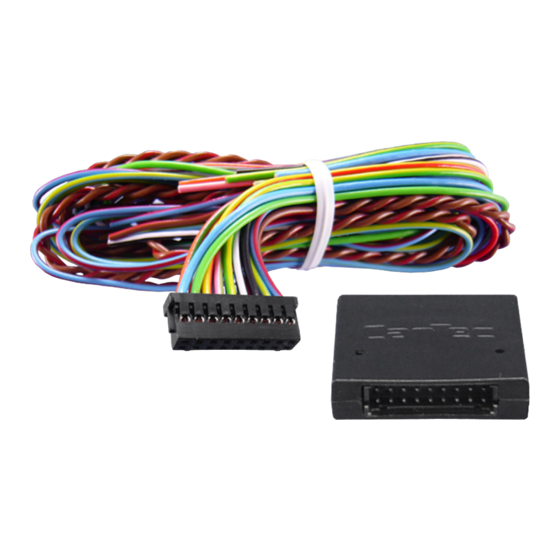
- Page 1 CAN-bus CAN-bus interface CANTEC-F2 CAN-bus interface with USB-support for analogue car-alarms, PDC & more 18.12.2019...
-
Page 2: Table Of Contents
8. Customer-specific programmable output/input configuration (complete) Product features CANTEC-F2 is a universal CAN-bus interface, hereafter referred to as unit, designed for connecting after-market car-alarm security, park-distance control, multimedia and service systems to vehicles with CAN-bus. The Unit has a build in micro USB port for easy programming with TECprog Software. -
Page 3: Prior To Installation
1.1. Delivery contents 1.2. Checking the compatibility of vehicle and function limitations Requirements Vehicle See CANTEC-F2 compatibility list at Limitations See CANTEC-F2 vehicle-specific installation files Vehicle-specific functions and compatibility list TECprog software look at: http://tecel.ru/en/tecprog/ www.navlinkz.de... -
Page 4: Pin Definition And Factory Defaults Of Programmable Outputs/Inputs
CAN-bus 2. Pin definition and factory defaults of programmable outputs/inputs Male pins of black-box 18pin port Programmable outputs/inputs configuration can be done out via programming (see chapter 4.) or via TEC-PROG tool and software with Windows PC. Factory defaults are predefined according to table 1. -
Page 5: Installation
CAN-bus 3. Installation 3.1. Power and CAN connections Disconnect the vehicle’s battery during installation or changes on the wiring! Connect +12V, Ground, CAN-high and CAN-low wires of the unit’s harness to the corresponding wires of the vehicle (see vehicle-specific installation file). Connect the unit’s black-box to its harness and make sure that all other open end wires of the harness do not short-circuit. -
Page 6: Forced Vehicle Recognition
CAN-bus 3.2.2. Forced vehicle recognition Forced vehicle recognition is only to be executed in exceptional cases, when automatic vehicle recognition has failed. Programming is carried out via programming button and LED indicator, which are located in the unit’s body. Prior to forced vehicle recognition, the vehicle group previously must not have been identified (if the vehicle group has previously already been identified, a factory reset is necessary) and the... -
Page 7: Programming
CAN-bus 4. Programming All programming is done by the unit’s programming button, LED and the vehicle’s brake pedal. The unit’s settings and input/output functions can be changed or checked in two menus after entering their programming modes. In MENU 1 it is possible to change settings –... - Page 8 CAN-bus Settings (MENU 1) – table2 Setting Option description range/ LED signals, notes default Forced vehicle recognition - / - See chapter 3.2.2. Forced vehicle recognition Forced vehicle group and sub-group assignment, when automatic has not worked. Original car alarm control -/disabled LED is on –...
- Page 9 CAN-bus In most cases the algorithm and polarity are set automatically when recognizing the vehicle. Hazard lights alternative 1-5 / - 1 – impulse negative control control algorithm of 2 – status negative control output pin 1 3 – impulse positive control 4 –...
-
Page 10: Programmable Outputs/Inputs Configuration (Menu 2)
CAN-bus 4.2. Programmable outputs/inputs configuration (MENU 2) In MENU 2, the programmable outputs and inputs can be set to other functions than the predefined factory defaults (see chapter 2.). Follow the below programming sequence to change or check programmable output/input functions of MENU 2: 1. - Page 11 CAN-bus assigning any of the available output functions to these two programmable outputs, it is necessary to set the required polarity. All other outputs are generally programmable and can be changed from their factory defaults (see chapter 2. - table 1) to any other available output function (see chapter 4.2.1., table 4) with max.
- Page 12 CAN-bus Available programmable output functions – table 4 Function Function description Security Constant level signal while the unit is in Secure mode. Arming impulse 0.8 sec long impulse when the unit is armed. Disarming 0.8 sec long impulse when the unit is disarmed. impulse Trunk opening 0.8 sec long impulse on trunk opening command of original...
- Page 13 CAN-bus Original buttons Constant level signal when a preprogrammed vehicle button is pressed. Programming sub-sequence: Without releasing the brake, press desired button (see vehicle specific installation file for visible buttons). Upon button identification, the unit stops emitting short light signals and emits series of 10 light signals. If brake is released prior to identification, the previous assignment stays saved.
-
Page 14: Programmable Inputs (Menu 2 - Options No. 13-16)
CAN-bus Rear parking Constant level signal for rear-parking sensors activation according sensors to algorithm chosen in MENU1 (table 2), no. 8 activation Parking distance Indicator the PDC system condition. control LED • If parking sensors work according to “Activation on rear indicator gear”... - Page 15 CAN-bus Input (+) pin 17 1-9/4 Hazard lights control Input (-) pin 18 1-9/3 Unlock trunk The setting range 1-9 in table 5, equals the available programmable input functions from table 6. Available programmable inputs functions – table 6 Function Function description Central locking Trigger input (impulse) for central locking.
-
Page 16: Reset To Factory Defaults
-40°C to +85°C Weight (box with harness) Dimensions (box only) B x H x T 30 x 30 x 7 mm 7. Technical Support NavLinkz GmbH TEC electronics ltd EU-distribution and tech dealer-support manufacturer Eurotec-Ring 45 16th Parkovaya 30, Bld.1 D-47445 Moers... -
Page 17: Customer-Specific Programmable Output/Input Configuration (Complete)
For reason of better comprehension, in chapter 4.2., programmable outputs and inputs are separated. Full configuration can be noted in the below table. For support reasons, we also suggest to apply the extra serial number sticker in CANTEC-F2 box here: ________________...
Need help?
Do you have a question about the CANTEC-F2 and is the answer not in the manual?
Questions and answers