
Related Manuals for TEC Electronics CANTEC-F2-U

Summary of Contents for TEC Electronics CANTEC-F2-U
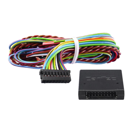
- Page 1 CAN-bus CAN-bus interface CANTEC-F2-U CAN-bus interface for analogue car-alarms, PDC & more Version 04.09.2015...
-
Page 2: Table Of Contents
CAN-bus Contents 1. Prior to installation 1.1. Delivery contents 1.2. Checking the compatibility of vehicle and function limitations 1.3. Planing programmable inputs and outputs 2. Pin definition and factory defaults of programmable outputs/inputs 3. Installation 3.1. Power and CAN connections 3.2. -
Page 3: Prior To Installation
CAN-bus 1. Prior to installation Read the manual prior to installation. Technical knowledge is necessary for installation. The place of installation must be free of moisture and away from heat sources. 1.1. Delivery contents 1.2. Checking the compatibility of vehicle and function limitations Requirements Vehicle See CANTEC-F2 compatibility list at... -
Page 4: Pin Definition And Factory Defaults Of Programmable Outputs/Inputs
CAN-bus 2. Pin definition and factory defaults of programmable outputs/inputs Male pins of black-box 18pin port Programmable outputs/inputs configuration can be done out via programming (see chapter 4.) or via TEC-PROG tool and software with Windows PC. Factory defaults are predefined according to table 1. -
Page 5: Installation
CAN-bus 3. Installation 3.1. Power and CAN connections Disconnect the vehicle’s battery during installation or changes on the wiring! Connect +12V, Ground, CAN-high and CAN-low wires of the unit’s harness to the corresponding wires of the vehicle (see vehicle-specific installation file). Connect the unit’s black-box to its harness and make sure that all other open end wires of the harness do not short-circuit. -
Page 6: Forced Vehicle Recognition
CAN-bus 3.2.2. Forced vehicle recognition Forced vehicle recognition is only to be executed in exceptional cases, when automatic vehicle recognition has failed. Programming is carried out via programming button and LED indicator, which are located in the unit’s body. Prior to forced vehicle recognition, the vehicle group previously must not have been identified (if the vehicle group has previously already been identified, a factory reset... -
Page 7: Connections Of Programmable Outputs/Inputs
CAN-bus 3.3. Connections of programmable outputs/inputs After successful vehicle recognition disconnect the unit’s black-box from its harness. Connect all the input and output wires to the corresponding places. Make sure that unneeded output/input wires are isolated. 4. Programming All programming is done by the unit’s programming button, LED and the vehicle’s brake pedal. - Page 8 CAN-bus *Note – If the vehicle’s brake pedal is not visible on CAN-bus (see vehicle-specific installation file), the unit’s trunk opening input is used (GND impulse instead of brake pedal press). Settings (MENU 1) – table2 Setting Option description range/ LED signals, notes default Forced vehicle recognition...
- Page 9 CAN-bus output pin 2 locking status is not available) In most cases the algorithm and polarity are set automatically when recognizing the vehicle. 1-5 / - Hazard lights alternative 1 – impulse negative control control algorithm of 2 – status negative control output pin 1 3 –...
-
Page 10: Programmable Outputs/Inputs Configuration (Menu 2)
CAN-bus 4.2. Programmable outputs/inputs configuration (MENU 2) In MENU 2, the programmable outputs and inputs can be set to other functions than the predefined factory defaults (see chapter 2.). Follow the below programming sequence to change or check programmable output/input functions of MENU 2: 1. -
Page 11: Programmable Outputs (Menu 2 - Options No. 1-12)
CAN-bus 8. Move to next option’s programming by pressing the programming button for the number of times required to navigate from current option’s number to the required option’s number while the last option’s number is followed by the first one. 9. - Page 12 CAN-bus Output (-) pin 5 1-24/22 Output (+) pin 6 1-24/21 Output (+) pin 7 1-24/11 Output (-) pin 13 1-24/1 Output (-) pin 14 1-24/8 Output (-) pin 15 1-24/8 Output (-) pin 16 1-24/8 The setting range 1-24 in table 3, equals the available programmable output functions from table 4.
- Page 13 CAN-bus input Doors, hood and Constant level signal when any of the preprogrammed doors, hood trunk or trunk is open. Programming sub-sequence: Any combination of doors, hood and trunk opening can be chosen to trigger this programmable output. For purpose of description, the doors, hood and trunk is below referred to as doors.
-
Page 14: Programmable Inputs (Menu 2 - Options No. 13-16)
CAN-bus required gear: P, N, D or R. Release and press the brake again. The unit stops emitting short light signals and indicates option setting number with series of 15 light signals. If the brake is not pressed, the previous assignment stays saved. After releasing the brake, the unit starts indicating the option’s no. - Page 15 CAN-bus It is possible to enter the from table 6 chosen input function for each programmable input into below table 5. Programmable inputs configuration (MENU 2) – table 5 Option Setting range / Notes (enter programmed/planned output description default functions from table 6) Input (-) pin 8 1-9/1 Input (-) pin 9...
-
Page 16: Reset To Factory Defaults
CAN-bus (status) file). PDC control Used for providing control of PDC (parking distance control) with button optional external button (required when no “visible” CAN-bus buttons available). 5. Reset to factory defaults By hardware reset, all programmable settings and functions of the unit are restored to factory default and the vehicle recognition (group and sub-group) is erased. -
Page 17: Technical Support
CAN-bus 7. Technical Support NavLinkz GmbH TEC electronics ltd EU-distribution and tech dealer-support manufacturer Eurotec-Ring 45 16th Parkovaya 30, Bld.1 D-47445 Moers 105484 Moscow, Russia +49 2841 94997 0 Email mail@navlinkz.de http://www.navlinkz.de http://www.canbus-alarm.com 8. Customer-specific programmable output/input configuration (complete) For reason of better comprehension, in chapter 4.2., programmable outputs and inputs are separated.
Need help?
Do you have a question about the CANTEC-F2-U and is the answer not in the manual?
Questions and answers