Table of Contents
Advertisement
Wood-Mizer
North America
Installation / Configuration Manual
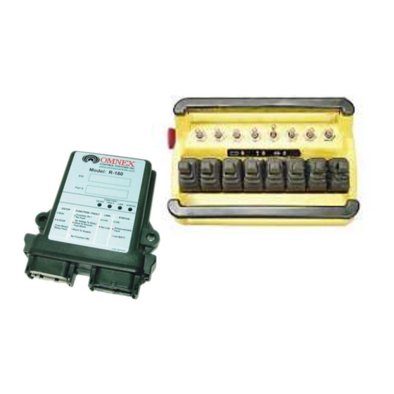
T300 Transmitter
R160 Receiver
March 27, 2008
DM-R160-0427A
Revision 2
#74-1833 Coast Meridian Road, Port Coquitlam, BC, Canada • V3C 6G5
Ph# (604) 944-9247 • Fax# (604) 944-9267
Toll Free 1-800-663-8806
call toll free: 1-800-663-8806
www.omnexcontrols.com
DM-R160-0427A (Rev 2)
1
Advertisement
Table of Contents

Related Manuals for Omnex ORIGA T300/R16

Summary of Contents for Omnex ORIGA T300/R16
- Page 1 Wood-Mizer North America Installation / Configuration Manual T300 Transmitter R160 Receiver March 27, 2008 DM-R160-0427A Revision 2 #74-1833 Coast Meridian Road, Port Coquitlam, BC, Canada • V3C 6G5 Ph# (604) 944-9247 • Fax# (604) 944-9267 Toll Free 1-800-663-8806 call toll free: 1-800-663-8806 www.omnexcontrols.com DM-R160-0427A (Rev 2)
-
Page 2: Table Of Contents
Table of Contents System Overview .................................3 Features..................................3 T300 Dimensions and Controls ............................3 Installing the Receiver ..............................4 Receiver Dimensions ..............................4 Special Functions .................................5 Installation Considerations............................6 Power the Transmitter ..............................6 Test the Transmitter / Receiver Link..........................7 Download ID Code................................7 Calibrating Proportional Controls..........................9 Diagnostics—T300 Transmitter ............................10 Diagnostics—R160 Receiver............................11 Troubleshooting Guide ..............................12... -
Page 3: System Overview
System Overview The ORIGA T300 / R160 is a portable, long range, programmable radio remote control system. Designed as a com- pact and easy-to-use product, this member of the ORIGA family puts complete control of your crane where it’s needed most, with the operator. It’s robust, easy to install and has complete self-diagnostics. This system can be a simple cable replacement or add intelligence to make it a total control package. -
Page 4: Installing The Receiver
Use the Wiring Diagram and the Connector Diagram below to connect the receiver pins directly to the appropriate contacts of the machine electronics. R160 Output Cables can be provided with every system to simplify the wiring proc- ess. The Wire Color column below only applies to the OMNEX Output Cable configuration. Tips on mounting, power connections and filtering are also provided under Installation Considerations. -
Page 5: Special Functions
Special Functions The DEBARKER ON output is only enabled while the HEAD TRAVEL FWD output is on. The Feed Speed Control Pot controls : Output 14—0 to 9.1VDC www.omnexcontrols.com call toll free: 1-800-663-8806 DM-R160-0427A (Rev 2) -
Page 6: Installation Considerations
The FCC and ISC require that the antenna be restricted to that supplied by the manufacturer and approved for use with this product. An op- tional 0dB coax wire antenna may be supplied. For other antenna options, please contact OMNEX Control Systems ULC Mounting and Installation The receiver can be mounted by fastening two ¼”... -
Page 7: Test The Transmitter / Receiver Link
Test the Transmitter / Receiver Link Follow these steps to ensure that there is a Radio Link between the transmitter and receiver Refer to the Light Legend below for diagram details 1. Press [E-Stop] 2. Power the R160 ESTOP FAULT LINK STATUS The (E Stop) light and the (Link) light will come on RED (provided the transmitter is off), and the (Status) - Page 8 Download ID Code (Use in case of Link Test failure) 3. Power R160 A. Supply power to the re- ceiver. The (E-Stop) light FAULT LINK STATUS ESTOP and the (Link) light will come on RED and the (Status) light will come on GREEN NOTE: For this document, orientation of the paddle and switch operation will...
-
Page 9: Calibrating Proportional Controls
Calibrating Proportional Controls The transmitter’s Paddles and Potentiometers control the receiver’s proportional output. The Paddles/Joysticks are used in conjunction with any of the transmitter’s switches. The proportional output can be activated when a switch is held UP or DOWN; it will become active at an increasingly high level as the Paddle/Joystick is pushed/pulled, or a potentiometer is adjusted. -
Page 10: Diagnostics-T300 Transmitter
Diagnostics—T300 Transmitter Tether connection detected STOP Low battery. Unit will run approximately 20 hours after Battery light starts flashing. STOP The transmitter is in Calibration mode STOP STOP Power switch is stuck in the “UP” position The Active light remain on momentarily when a function is activated (i.e. a switch or STOP paddle is triggered). -
Page 11: Diagnostics-R160 Receiver
Diagnostics - R160 Receiver Normal Operation ESTOP FAULT LINK STATUS Transmitter is OFF If the transmitter is off, the receiver is operating properly. Transmitter is ON FAULT LINK ESTOP STATUS When the transmitter is turned on, the Link light (fast flashing) and E-Stop (GREEN) indicates the receiver is operating properly Transmitter is in Operation ESTOP... -
Page 12: Troubleshooting Guide
Troubleshooting Guide Chart #1 Test the Receiver—R160 OK state: Start Status—GREEN Initial Condition: Link—RED Turn transmitter off (all lights are off—press the What is the state E-Stop—RED E-Stop button) of the lights on Fault—OFF Cycle power to receiver (turn off and back on) the receiver? Note: If there is a short to ground on an output, it is not indicated at this... - Page 13 Troubleshooting Guide (con’t) Chart #2 Test the Transmitter—T300 Turn off the receiver Ensure there are good batteries in the transmitter Turn on the transmitter OK state: Active light—steady for about 3 seconds then Toggle a switch What is the state of or paddle goes to fast flash.
- Page 14 Troubleshooting Guide (con’t) Chart #3 Testing the Transmitter / Receiver Communication Transmitter: Transmitter: Active light is flashing Active light is flashing Receiver: What is the status of Receiver: Status—GREEN the lights of both the Status—GREEN Link—RED transmitter and Link—Flashing GREEN Fault—OFF receiver? Fault—OFF...
- Page 15 Troubleshooting Guide (con’t) Chart #4 Considerations when Downloading the ID Potential downloading issues If testing of the receiver and transmitter both show the system as working (Chart 1 & 2), then the transmitter and receiver will both go into Download/Configuration mode. Possible issues could arise during Step 4, the download phase of reprogramming.
-
Page 16: Parts & Accessories
OMNEX's entire liability and your exclusive remedy shall be, at OM- (2) this device must accept any V3C 6G5 NEX's option, either the (a) repair or (b) replacement of the OMNEX product interference received, including...
Need help?
Do you have a question about the ORIGA T300/R16 and is the answer not in the manual?
Questions and answers