Table of Contents
Advertisement
Quick Links
SERVICE MANUAL
YM6000 Patient Monitor
EU representative
TECNOMED 2000 S.L.
Valencia, 25 ‐ 28012 Madrid Spain
Manufacturer
Mediana Co., Ltd.
Wonju Medical Industry Park, 1650‐1 Donghwa‐ri,
Munmak‐eup, Wonju‐si, Gangwon‐do, Korea
Tel: (82) 2 542 3375 (82) 33 742 5400
Fax: (82) 2 542 7447 (82) 33 742‐5483
YM6000 Service Manual
Revised Date: 0607
Part Number‐Revision: A7066‐1
Printed in Korea
Copyright © 2006‐2007 Mediana Co., Ltd. All rights reserved.
Advertisement
Table of Contents
Troubleshooting

Related Manuals for Mediana YM6000

Summary of Contents for Mediana YM6000
- Page 1 SERVICE MANUAL YM6000 Patient Monitor EU representative TECNOMED 2000 S.L. Valencia, 25 ‐ 28012 Madrid Spain Manufacturer Mediana Co., Ltd. Wonju Medical Industry Park, 1650‐1 Donghwa‐ri, Munmak‐eup, Wonju‐si, Gangwon‐do, Korea Tel: (82) 2 542 3375 (82) 33 742 5400 Fax: (82) 2 542 7447 (82) 33 742‐5483 YM6000 Service Manual Revised Date: 0607 Part Number‐Revision: A7066‐1 ...
- Page 2 This document contains proprietary information that is protected by copyright. All Rights Reserved. Reproduction, adaptation, or translation without prior written permission is prohibited, except as allowed under the copyright laws. Warranty The information contained in this document is subject to change without notice. Mediana makes no warranty of any kind with regard to this material, including, but not limited to, the implied warranties or merchantability and fitness for a particular purpose. Mediana shall not be liable for errors contained herein or for incidental or consequential damages in connection with the furnishing, performance, or use of this material. Revision History The documentation part number and revision number indicate its current edition. The revision ...
-
Page 3: Table Of Contents
Contents Introduction ................................1 Warnings ................................. 1 Cautions ................................2 Manual Overview ............................3 Related Documents............................3 Intended Use for the YM6000 Monitor ....................... 3 Identifying the YM6000 monitor Configurations ..................3 Monitor Controls............................4 Routine Maintenance............................9 Cleaning ................................9 Periodic Safety and Functional Checks....................... 9 Batteries ................................. 10 Environmental Protection........................... 10 Performance Verification............................ 11 General ................................11 Required Equipment ........................... - Page 4 Figure 30. Process Unit Block Diagram ..........................84 Figure 31. User‐Control Unit Block Diagram.........................84 Figure 32. Sound Unit Block Diagram............................85 Figure 33. Communication Unit Block Diagram ........................85 Figure 34. GUI Unit Block Diagram............................85 Figure 35. Thermal Printer Unit Block Diagram ........................85 Figure 36. NIBP Unit Block Diagram.............................86 Figure 37. EtCO Unit Block Diagram ...........................86 Figure 38. ECG Unit Block Diagram ............................86 Figure 39. Respiration Unit Block Diagram..........................87 Figure 40. SpO Unit Block Diagram............................87 Figure 41. Temperature Unit Block Diagram ..........................87 Figure 42. IBP Unit Block Diagram ............................88 Figure 43. Analog Control Unit Block Diagram ........................88 Figure 44. Oxyhemoglobin Dissociation Curve........................92 Tables Table 1. Required Equipment..............................11 Table 2. Parameter Alarm Limit Factory Defaults........................18 Table 3. Earth Leakage Current Values ............................31 Table 4. Enclosure Leakage Current............................32 Table 5. Patient Leakage Current Values ..........................33 Table 6. Patient Leakage Current Values ‐ Mains Voltage on Applied Part................33 Table 7. Test Lead Combinations..............................34 Table 8. Allowable Leakage Current............................34 Table 9. Service Menu................................37 YM6000 Service Manual...
- Page 5 Table 10. Audible Alarm Characteristics ..........................38 Table 11. System Test ................................39 Table 12. NIBP Test .................................40 Table 13. Factory Default Settings ............................40 Table 14. Required Equipments for Firmware download ......................45 Table 15. Completion codes ..............................46 Table 16. Firmware Downloading Error Codes ........................54 Table 17. Alarm Messages and Check Items ..........................54 Table 18. Part Descriptions – Battery and Handle ........................64 Table 19. Part Descriptions – Monitor ............................65 Table 20. Part Descriptions – Side connector holder and Main board ..................66 Table 21. Part Descriptions – CPU module, SpO module and IBP board ................67 Table 22. Part Descriptions –Bracket and Key board.......................68 Table 23. Part Descriptions – LCD and Bracket........................69 Table 24. Part Descriptions – Knob, LCD window, Encoder assembly and Connectors............70 Table 25. Part Descriptions – EtCO module ..........................72 Table 26. Part Descriptions – Speaker .............................73 Table 27. Part Descriptions –SMPS case, SMPS and NIBP module ..................74 Table 28. Part Descriptions – Printer module and AC inlet....................75 Table 29. Parts List ..................................79 YM6000 Service Manual...
- Page 6 Contents This page is intentionally left blank. YM6000 Service Manual...
-
Page 7: Introduction
Performance Tests and Safety Tests listed in Performance Verification section of this service manual have been performed. Failure to perform all tests could result in erroneous monitor readings. WARNING: High voltage is generated by the LCD backlight driver. Exercise caution when operating monitor with covers open. YM6000 Service Manual... -
Page 8: Cautions
Operating error may be caused if the cover is not closed correctly. CAUTION: If internal battery cable has been disconnected, pay particular attention to polarity of the cable before reattaching. If battery cable polarity is reversed, it is likely that circuit damage will occur. CAUTION: For continued protection against risk of fire, replace only with same type and rating of fuse. CAUTION: Ferrite Cores are used for electromagnetic compatibility. Please do not remove Ferrite Cores while disassembling or reassembling, otherwise the monitor can be affected by electromagnetic interference and measure inaccurate data to be displayed or stored. YM6000 Service Manual... -
Page 9: Manual Overview
Hospital‐type facilities include physician office‐based facilities, sleep labs, skilled nursing facilities, surgicenters, and sub‐acutecenters. Identifying the YM6000 monitor Configurations The following table identifies YM6000 monitor configurations and how they are indicated. The model‐option number and serial number are located on the back of the monitor. All information in this manual, including the illustrations, is based on a monitor configured with the Capnography (EtCO and InCO ), ... -
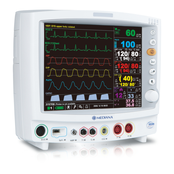
Page 10: Monitor Controls
6 AC indicator 7 Power button 8 Print button 9 Alarm silence/suspension button 10 Trend button 11 NIBP start/stop button 12 Return button 13 Trim knob 14 ECG connector 15 SpO connector 16 NIBP connector 17 Temperature channel 1 18 Temperature channel 2 19 CO connector (option) 20 IBP 1 connector (option) 21 IBP 2 connector (option) Figure 1. Front Panel Controls and Connectors YM6000 Service Manual... -
Page 11: Figure 2. Rear Panel Components And Symbols
Introduction 5 Rear Panel Components 1 Air ventilation Battery cover 2 Equipotential terminal Thermal Printer (option) 3 Ac power connector Handle 4 Speaker Figure 2. Rear Panel Components and Symbols YM6000 Service Manual... -
Page 12: Figure 3. Right Panel Components And Symbols
6 Introduction Right Panel Components 1 LAN connector 2 RS‐232 interface connector Figure 3. Right Panel Components and Symbols YM6000 Service Manual... -
Page 13: Figure 4. Left Panel Components And Symbols
Introduction 7 Left Panel Components 1 Thermal printer (option) 2 Battery cover Figure 4. Left Panel Components and Symbols YM6000 Service Manual... - Page 14 8 Introduction This page is intentionally left blank. YM6000 Service Manual...
-
Page 15: Routine Maintenance
3. If the monitor has been visibly damaged or subjected to mechanical shock (for example, if dropped), perform the performance tests as described in Performance Verification section. If the unit fails these performance tets, refer to Troublehooting section. 4. Perform the electrical safety tests detailed in Performance Verification section. If the unit fails these electrical safety tests, do not attempt to repair. Contact Mediana Technical Service Department. 5. Inspect the fuses for proper value and rating. qty 2, 6.3 A, 250 volts for AC mains YM6000 Service Manual... -
Page 16: Batteries
Operation section of the operator’s manual. Note: Storing the monitor for a long period without charging the battery may degrade the battery capacity. The battery may require a full charge/discharge cycle to restore normal capacity. Mediana recommends that the monitor’s sealed, Ni‐ MH batteries be replaced at 2 year intervals. Refer to Disassembly Guide section. CAUTION: If the monitor is to be stored for a period of 2 months or longer, it is ... -
Page 17: Performance Verification
Sample elbow or tee gas flow meter BCI catalogue No. 8133 recommended Sample line Sample line Water trap Water trap scrubber scrubber (or 0% CO medical‐grade gas source) (or 0% CO medical‐grade gas source) Safety analyzer METRON QA‐90 or equivalent Data interface cable 9‐pin RS‐232 cable PC Common PC LAN cable Common used LAN cable Stopwatch Manual or electronic Note: Contact Mediana Technical Service Department for pricing and ordering information. YM6000 Service Manual... -
Page 18: System Tests
2. The level of the alarm tone will appear on the screen as the alarm tone sounds. Then, the level goes up gradually. When the tone reaches the maximum level 8, it returns to the minimum level 1. 3. After finishing the test, press the trim knob to select Cancel. The menu box will disappear. Pass/Fail Results When the alarm tone changes to eight steps, the alarm tone is in a normal state. YM6000 Service Manual... -
Page 19: Figure 6. Tone Audible Test
When the tone returns to the minimum, the pitch will change automatically. There are three pitches – High, Med and Low. 3. Press Cancel to finish the test. 4. Rotate the trim knob to select Key Beep. The key beep sounds intermittently as the level goes up gradually. When the tone reaches the maximum level 7, it returns to the minimum 1. 5. After finishing the test, press the trim knob to select Cancel. The menu box will disappear. Pass/Fail Results When the HR/PR tone changes to seven steps and the pitch changes to three steps, the HR/PR tone is normally set. When the key beep changes to seven steps, the key beep is normally set. When the completion sound is heard, it is normally set. YM6000 Service Manual... -
Page 20: Figure 7. Backup Ram Clear
14 Performance Verification Backup RAM Clear When Backup RAM Clear is set to Yes, all settings of the monitor including the service settings return to the factory defaults from the next cycle. Figure 7. Backup RAM Clear Note: Set the monitor to appropriate AC line frequency (50Hz or 60Hz) again after Back Up RAM clearance. YM6000 Service Manual... -
Page 21: Performance Tests
8. Set NIBP Automatic mode interval of the monitor to 15 minutes. 9. The monitor must operate for 1 hour with one fully charged battery. The monitor must operate for at least 15 minutes before the monitor powers down due to low battery condition. 10. Verify that low priority audible alarm occurs and a warning message “low battery” is displayed about 15 minutes before battery fully discharges. YM6000 Service Manual... - Page 22 2. Observe the monitor’s front panel. With monitor off, press Power button. The monitor must perform the following sequence. The monitor progresses the check sum for the flash memory and displays the bar while the check sum is proceeding When the check sum completed, the bar is filled, and then Mediana logo appears for a few seconds, with version numbers of the software and the copyright in lower left corner of display. The monitor emits the high‐pitched beep. ...
- Page 23 HR/PR Tone Volume Control 1. Press Power button to turn on the monitor. 2. Connect SpO simulator to sensor input cable and connect cable to monitor. 3. Set SpO simulator as follows: SpO of 75% and pulse rate of 60bpm. 4. Verify SpO and pulse rate values are correctly displayed. 5. Press Alarm silence/suspension button on front panel of the monitor to temporarily silence audible alarm. 6. Verify HR/PR source on HR/PR numerical area is set to “SpO ”. 7. Select Setup icon on the screen to display Setup menu. 8. Rotate the trim knob to highlight HR/PR tone volume on Setup menu and press the trim knob to adjust HR/PR tone volume. 9. Set HR/PR tone volume level 1 to level 7 and return to the monitoring screen. Verify beeping pulse rate tone increases. 10. Set HR/PR tone volume level 7 to level 1 and return to the monitoring screen. Verify beeping pulse rate tone decreases. YM6000 Service Manual...
-
Page 24: Table 2. Parameter Alarm Limit Factory Defaults
High Alarm Limits 100 % 100 % 95 % % SpO Low Alarm Limits 90 % 90 % 80 % IBP1, 2 SYS High Alarm Limits 160 mmHg 120 mmHg 90 mmHg IBP1, 2 SYS Low Alarm Limits 90 mmHg 70 mmHg 40 mmHg IBP1, 2 DIA High Alarm Limits 90 mmHg 70 mmHg 60 mmHg IBP1, 2 DIA Low Alarm Limits 50 mmHg 40 mmHg 20 mmHg IBP1, 2 MEAN High Alarm Limits 110 mmHg 90 mmHg 70 mmHg IBP1, 2 MEAN Low Alarm Limits 60 mmHg 50 mmHg 30 mmHg RESP High Alarm Limits 30 BPM 30 BPM 100 BPM YM6000 Service Manual... - Page 25 2. Press Power button to turn on the monitor. 3. Connect all necessary simulators to the monitor. 4. Select Setup icon on the screen to display Setup menu. 5. Test #1: 20 sec printing Set Wave record time to 20 sec via Setup menu. Press Print button when all the parameter signals display normally. Verify that the parameter values and waveforms are printed out for 20 seconds. 6. Test #2: Continuous printing Set Wave record time to Continuous via Setup menu. Press Print button when all the parameter signals display normally. Verify the parameter values and waveforms are printed out continuously. Verify printing stops with pressing Print button again. YM6000 Service Manual...
- Page 26 Network Test Perform the following procedure to test the Network. The Network connector is located on the monitor’s right panel, identified with the Network symbol. CAUTION: Do not change any other settings of the test programs while performing the Network test. Note: Network Test is only available when YM6000 monitor is equipped with TCP/IP module for Central Monitoring System (CMS). Otherwise this test does not need to perform. Note: Contact Mediana Technical Service Department for the software required. 1. Connect the network line to the monitor, then turn on the monitor. 2. Run “YM6000_Comm_Test.exe” on PC connected the network line using the same gateway as the monitor. ...
- Page 27 5 and 1 must be between ‐5 to ‐12 VDC. This verifies the RS‐232 Nurse Call function. 7. With the instrument in an alarm condition, use a digital multmeter (DMM) to verify that there is no continuity (1 mega ohms or greater) between pins 8 and 9 and that there is continuity (60 ohms or less) between pins 7 and 8. 8. Press the SRC‐MAX simulator %SpO button to change the %SpO to 90. 9. Use a DMM to verify that there is continuity between pins 8 and 9 and that there is no continuity between pins 7 and 8. This verifies the solid state Nurse Call function. Note: The pin layouts and signal descriptions are included in the operator’s manual. For the detailed information regarding the Nurse Call, refer to Nurse Call Interface section of the operator’s manual. YM6000 Service Manual...
- Page 28 HR/PR numerical area, and that low priority audible alarm sounds. Reconnect the LL lead to ECG simulator. Verify that “ECG: Check ECG leads & electrodes” message no longer appears and that the audible alarm is stopped. Repeat this test for the LA and the RA leads. 10. Connect all the leads to the monitor. Select ECG waveform menu and set Lead select to Lead I. Verify that the lead selection is displayed on the ECG waveform area. Repeat step 10‐a for all the ECG Lead selections. 11. Set ECG Lead selection to Lead II. 12. Change ECG waveform size to all the selectable sizes and verify that an appropriate size is displayed on the ECG waveform area. YM6000 Service Manual...
- Page 29 These tests verify the functionality of the monitor’s pneumatic system. The monitor must be placed in Service menu. For a detailed explanation to access the service menu, refer to Service Menu and Factory Default Settings section. 1. Rotate the trim knob to select NIBP Test in the service menu, and then press the trim knob. Note: Before accessing the NIBP Test mode, ensure that current patient mode is proper for the pneumatic system to be test. You can set Patient mode: Adult, Pediatric or Neonatal via the setup menu. Note: In the NIBP Test mode, no function button will have no effect except the trim knob. All the tests will start to be performed by pressing or rotating the trim knob. If you would like to stop the test during test progressing, press the trim knob. Note: Inflation Speed Test and Deflation Speed Test are intended for factory use only. YM6000 Service Manual...
-
Page 30: Figure 8. Pressure Sensor Accuracy Test
8. After finishing the test, press the trim knob to select Cancel. The menu box will disappear. If Cancel is selected during the test progressing, the test will stop and the menu box will disappear. Pass/Fail Results The difference between the simulator’s and the monitor’s readings are as follows: Sphygmomanometer Monitor’s Readings 0 mmHg ±0 mmHg 50 mmHg 50±6 mmHg 100 mmHg 100±6 mmHg 200 mmHg 200±6 mmHg YM6000 Service Manual... -
Page 31: Figure 9. Air Leakage Test
4. Rotate the trim knob to select Air Leakage Test, and then press the trim knob. 5. The result will be displayed on the monitor’s screen in four minutes. 6. After finishing the test, press the trim knob to select Cancel. The menu box will disappear. If Cancel is selected during the test progressing, the test will stop and the menu box will disappear. Pass/Fail Results It passes if the leakage value is less than 12mmHg/3minutes. YM6000 Service Manual... - Page 32 The monitor will decrease to 60 and stabilize at 60bpm. The test pass criteria is 57 to 63 bpm. The monitor will display: ‐ 90 % SpO ‐ 60 bpm ‐ no alarm ‐ low level modulation 8. Test #3: Modulation Level Press %MODULATION selection button on the SpO simulator. The %MODULATION LED on the SpO simulator will light. The monitor’s waveform area will spike and stabilizes at a higher modulation level. The monitor will display: ‐ 90 % SpO YM6000 Service Manual...
- Page 33 2. Connect the temperature probe (supplied with the temperature simulator) to an appropriate jack on temperature simulator. 3. Connect the temperature probe to the temperature connector on the monitor’s front panel. 4. Set Temperature simulator as follows: Temperature: 37°C (98.0°F) Probe type: YSI‐400 series Temperature Probes (Probe accuracy: ±0.1°C) 5. After the normal power‐up sequence, verify that the temperature reads 37°C ±0.1°C (98.6°F ±0.2°F if Fahrenheit is selected for the temperature units). 6. Turn off the monitor. Note: The accuracy of temperature measurements is ±0.1°C (±0.2°F) in the range of 25°C to 45°C and ±0.2°C in the range of 15° C to less than 25° C. In the procedure above, add the tolerance of the simulator and the probe to the acceptable range of readings. YM6000 Service Manual...
- Page 34 9. Press the 5, wavef button on the IBP simulator, then press enter button on the IBP simulator. 10. The monitor will: ‐ display IBP waveform on the screen. ‐ display systolic, mean, diastolic measurement values on the IBP numerical area. Note: Initial values of IBP simulator are systolic 120mmHg, diastolic 80mmHg at channel 1, systolic 120mmHg, diastolic 0mmHg at channel 2. YM6000 Service Manual...
- Page 35 After approximately one minute, observe the CO reading. The CO reading should be between 0.0%~0.3% with well‐ventilated room air. Proceed with the zero gas phase of the calibration as defined by the host system. Disconnect the CO scrubber (or gas source) from the water trap after the zero gas calibration. YM6000 Service Manual...
- Page 36 Make sure the bleed line is directed away from the monitor. Allow the reference gas to flow for at least one minute. h. Sample the Span Reference Gas. After the Two‐Point User Calibration steps have been followed, disconnect the monitor from the gas supply and test setup. A verification may be performed using the same gas delivery set up. Verify the observed CO gas reading is within 3 mmHg or 10%, whichever is greater, of the CO value of the test gas supplied. (If not, refer the user to the appropriate troubleshooting information.) YM6000 Service Manual...
-
Page 37: Safety Tests
This test is in compliance with IEC60601‐1 enclosure leakage current. This test is for ungrounded enclosure current, measured between enclosure parts and earth. The applied voltage for IEC60601‐1 the applied voltage is 264 Volts AC at 50 to 60 Hz. 1. Connect the monitor AC plug to the electrical safety analyzer as recommended by the analyzer operating instructions. 2. Place a 200cm foil in contact with the instrument case making sure the foil is not in contact with any metal parts of the enclosure that may be grounded. 3. Measure the leakage current between the foil and earth. Note: The analyzer leakage current indication must not exceed the values listed in Table 4. YM6000 Service Manual... -
Page 38: Table 4. Enclosure Leakage Current
Note: This test requires a test cable for each patient connector. For example, the ECG test cable consists of the ECG cable connector, with all conductors shorted together, connected to a test lead from the electrical safety analyzer. Test cables for SpO and temperature can be configured in a similar manner, by wrapping each sensor end individually with aluminum foil filled with conductive gel (only enough gel to ensure conductivity). Attach a wire to the foil that is connected to a test lead from the electrical safety analyzer. YM6000 Service Manual... -
Page 39: Table 5. Patient Leakage Current Values
2. Connect monitor’s AC mains power cord to analyzer as recommended by analyzer operating instructions. 3. Connect ECG test cable between ECG connector on the monitor and appropriate input connector on analyzer. 4. Turn on the monitor. 5. Perform the test as recommended by analyzer operating instructions. 6. Repeat the test for SpO and temperature patient connections, using appropriate test cables. Note: Patient leakage current is measured with normal and reverse mains polarity. For each condition, the measured leakage current must not exceed that indicated in Table 6. Table 6. Patient Leakage Current Values ‐ Mains Voltage on Applied Part Test Condition Allowable Leakage Current (microamps) Normal polarity (SFC) 50 Reverse polarity (SFCRM) 50 YM6000 Service Manual... -
Page 40: Table 7. Test Lead Combinations
ECG #1 (LA) ECG #2 (LL) ECG #1 (LA) ECG # 3 (RA) ECG #2 (LL) ECG #3 (RA) ECG #1 (LA) Temperature 1/2 ECG #2 (LL) Temperature 1/2 ECG #3 (RA) Temperature 1/2 ECG #1 (LA) ECG #2 (LL) ECG #3 (RA) Temperature 1/2 Table 8. Allowable Leakage Current Test Condition Allowable Leakage Current (microamps) Normal Condition (NC) 10 SFC Open Supply (OS) 50 SFC Open Earth (SFC OE) 50 Normal Condition RM (NCRM) 10 SFC Open Supply RM (SFC OSRM) 50 SRC Open Earth RM (SFC OERM) 50 YM6000 Service Manual... -
Page 41: Service Menu And Factory Default Settings
Once the Service menu is entered, physiological monitoring is terminated. The screen layouts do not display any information associated with normal monitoring operation. Use the following procedure to configure the Service Menu for the monitor (also see Using the Monitor section, of the operator’s manual): Figure 10. The access of Service Menu via Set‐up menu 1. Set the monitor to normal monitoring mode. 2. Rotate the trim knob to highlight the Setup icon located on the bottom of the screen, and then press the trim knob. Setup menu displays. 3. Rotate the trim knob to highlight Service Menu in Setup menu, and then press the trim knob to access the Service Menu. 4. Three digits are displayed in the Level 2 Menu as shown in Figure 4. YM6000 Service Manual... -
Page 42: Figure 11. The Access Of Service Menu Via Set-Up Menu
8. The Service Menu will now be present. The available Service Menu items are explained in Figure 6 and Table 9. Make changes to these menu items as desired by rotating and pressing the trim knob. 9. Select “Done”. The monitor will present the message “All changes made to the power‐up defaults will be in effect the next time the monitor is turned on.” Before turned off. 10. Turn off the monitor, and then turn on the monitor again. Note: The monitor must be powered off upon selecting “Done” to save any changes into the monitor, and then the changes made to the Power on defaults will be in effect next time the monitor is powered up. YM6000 Service Manual... -
Page 43: Table 9. Service Menu
System Test LCD Test Alarm Audible Test Tone Audible Test Backup RAM Clear NIBP Test Pressure Sensor Accuracy Test Air Leakage Test Inflation Speed Test Deflations Speed Test Demo Mode On, Off EtCO Calibration Zero Calibration, Calibration Done The monitor will be powered off upon selecting “Done”, then any changes in the service menu will be in effect next time the unit is powered up. Saved setting on Power off If the save settings on power off is set to Custom, the monitor does not save the settings when the monitor is power off. Therefore, the first settings when the monitor is powered up become the power‐up defaults in the next power‐on cycling. If the save settings on power off is set to Back Up, the monitor saves the current settings when the monitor is powered off. The saved settings become the power‐on defaults in the next power‐on cycling. If the save settings on power off is set to Default, the factory default settings become the power‐up defaults in the next power‐on cycling. YM6000 Service Manual... - Page 44 IEC60601‐1‐8 High priority ~976 Hz ~976 Hz 7 beeps in 2 sec 10 beeps in 15 sec Medium priority ~697 Hz ~697 Hz 2 beeps in 1 sec 3 beeps in 15 sec Low priority ~488 Hz ~488 Hz 1 beeps in 5 sec 1 beeps in 30 sec AC Line Frequency The monitor supports AC line frequency both 50 Hz and 60 Hz. Select either 50Hz or 60 Hz for an appropriate AC line. Unit Configuration The unit configuration of each parameter can be set in the service menu. Language Setting The selected language will be used for all the text shown on the display; and it will be effective the next time the monitor is powered up. Date Format The date format is selectable; Year/Month/Day, Month/Day/Year, Day/Month/Year Alarm Reminder Tone The monitor generates the alarm reminder tone at the preset interval to remind the user that the audible alarm is suspended. The interval can be set to Off, 3 or 10 minutes via the service menu. If Off is selected, the reminder tone will be disabled. YM6000 Service Manual...
- Page 45 Discharges may not be reset, but they will be reset to zero when a new CPU module is installed. System Test These menus provide to facilitate performing verification testing for the overall system. For a detailed procedure, refer to Performance Verification section. Table 11. System Test Tests Description LCD Test tests the LCD display. Alarm Audible Test tests the alarm tones. Tone audible Test tests the HR/PR tones, the key beeps and the completion sounds. Backup RAM Clear is used to set the factory defaults. YM6000 Service Manual...
-
Page 46: Demo Mode
80, 100, 120, 140mmHg (13.3, 16.0, 17.3, 18.7 kPa) BP On Alarm On, Off Off Off Off NIBP Interval Off, Cont, 1, 2, 2.5, 3, 5, 10, 15, 20, 30, 45, Off Off Off 60, 90,120 ,180 minutes NIBP SYS High Alarm Limits adult/pediatric 160 mmHg 120 mmHg 90 mmHg 35 to 270 mmHg (4.7 to 36.0 kPa) (21.3 kPa) (16.0 kPa) (12.0 kPa) neonatal 45 to 130 mmHg (6.0 to 17.3 kPa) (5 mmHg, 0.7kPa steps) adult/pediatric NIBP SYS Low Alarm Limits 90 mmHg 70 mmHg 40 mmHg 30 to 265 mmHg (4.0 to 36.3 kPa) (12.0 kPa) (9.3 kPa) (5.3 kPa) neonatal 40 to 125 mmHg (5.3 to 16.7 kPa) YM6000 Service Manual... - Page 47 IBP 2 DIA High Alarm Limits 90 mmHg 70 mmHg 60 mmHg ‐45 to 300 mmHg (‐6 to 40 kPa) (12.0 kPa) (9.3 kPa) (8.0 kPa) (5 mmHg, 0.7kPa steps) adult/pediatric/neonatal IBP 2 DIA Low Alarm Limits 50 mmHg 40 mmHg 20 mmHg ‐50 to 295mmHg (‐6.7 to 39.3 kPa) (6.7 kPa) (5.3 kPa) (2.7 kPa) (5 mmHg, 0.7kPa steps) adult/pediatric/neonatal IBP 2 MEAN High Alarm 110 mmHg 90 mmHg 70 mmHg ‐45 to 300 mmHg (‐6 to 40 kPa) Limits (14.7 kPa) (12.0 kPa) (9.3 kPa) (5 mmHg, 0.7kPa steps) adult/pediatric/neonatal IBP 2 MEAN Low Alarm 60 mmHg 50 mmHg 30 mmHg YM6000 Service Manual...
- Page 48 0 to 2.4 kPa (Adult/Neo) (0.3 kPa steps) 0 % 0 % 0 % 0 to 2.3 % (Adult/Neo) (0.3 % steps) Temperature TEMP1 High Alarm Limits 15.1 to 45.0 °C (0.1°C steps) 39.0 °C 39.0 °C 39.0 °C 59.1 to 113.0 °F (0.1°F steps) (102.2 °F) (102.2 °F) (102.2 °F) TEMP1 Low Alarm Limits 15.0 to 44.9 °C (0.1°C steps) 36.0 °C 36.0 °C 36.0 °C 59.0 to 112.8 °F (0.1°F steps) (96.8 °F) (96.8 °F) (96.8 °F) TEMP2 High Alarm Limits 15.1 to 45.0 °C (0.1°C steps) 39.0 °C 39.0 °C 39.0 °C 59.1 to 113.0 °F (0.1°F steps) (102.2 °F) (102.2 °F) (102.2 °F) YM6000 Service Manual...
- Page 49 한국어 (Korean), 中文 (Chinese), English, Français (French), Deutsch (German), Italiano (Italian), 日本語 Language* English (Japanese), Português (Portuguese), Español (Spanish) : Note An asterisk (*) by a parameter in the above table indicates that the parameter can only be changed by authorized personnel as described in the monitor service manual Note: Asterisks (**) by a parameter in the above table indicate the print settings when the optional printer is installed in the monitor YM6000 Service Manual...
- Page 50 44 Service Menu and Factory Default Settings This page is intentionally left blank. YM6000 Service Manual...
-
Page 51: Firmware Download
1. Turn the monitor off. 2. Turn the monitor on by pressing the Power button. 3. The monitor displays the bar while the checksum for the flash memory is in progress. 4. Press NIBP start/stop button and Return button simultaneously before filled the bar completely. 5. The monitor will display the firmware download screen as shown below figure 13. Figure 13. Firmware downloading display YM6000 Service Manual... -
Page 52: Figure 14. Firmware Downloading Display
Table 15. Completion codes Code Description S. 1. 3 Boot download completed. S. 2. 3 Main download completed. Note: If any problem during Firmware downloading, the error code will be displayed in the box located on the center of the screen. Refer to Firmware Download in Troubleshooting section. 10. After completion of downloading, turn the monitor off. 11. Disconnect the LAN cable from the monitor. 12. After a few seconds, turn the monitor on again. 13. Perform the tests specified in Performance Verification section. Note: When a new firmware downloading is completed, the monitor is set to the factory default. YM6000 Service Manual... -
Page 53: Troubleshooting
If the trouble symptom persists, swap back the replacement PCB assembly with the suspected malfunctioning PCB assembly (the original PCB assembly that was installed when you started troubleshooting) and continue troubleshooting as directed in this section. Obtaining Replacement Parts Mediana Technical Service Department provides technical assistance information and replacement parts. To obtain replacement parts, contact Mediana. Refer to the part names and part numbers listed in Spare Parts section. YM6000 Service Manual... -
Page 54: Troubleshooting Guide
1. When AC power cord is connected to the monitor, AC indicator on the front panel is not lit. 1‐1 Ensure power cord is plugged into the appropriate AC outlet of voltage and frequency. 1‐2 Replace the power supply assembly. 1‐3 Ensure the key wire is connected to the key board assembly and the main board. If the connection is good, replace the key board assembly. 2. The monitor fails to power‐up when the power button is pressed. 2‐1 Ensure power cord is plugged into operational AC outlet of the appropriate voltage and frequency. Ensure AC power indicator is lit. If indicator is not lit, replace the power supply assembly. 2‐2 Check fuses located on the power supply assembly above AC inlet receptacle. Replace fuses if necessary. 2‐3 Inside monitor, check the main cable and ensure that it is connected to the main board and the power supply assembly. 2‐4 Ensure the key board assembly is connected to the main board. If connection is good, replace the key board assembly. 2‐5 If the problem persists, replace the main board. 3. The monitor turns on, then sounds an alarm and shuts off and no error code is displayed. 3‐1 Replace the main board. YM6000 Service Manual... - Page 55 If the action requires replacement of a PCB assembly or module, refer to Disassembly Guide. 1. LCD screen is totally black after system powers‐up. 1‐1 Ensure the inverter wire is connected to the LCD assembly. 1‐2 Ensure the LCD cable is connected to the LCD assembly and the main board. 1‐3 If the problem persists, replace LCD assembly. 1‐4 If the problem persists, replace the main board. 2. LCD screen is illuminated, but no data is visible after system powers‐up. 2‐1 Ensure LCD cable is connected to the main board and LCD assembly. 2‐2 If the problem persists, replace the LCD cable. 2‐3 If the problem persists, replace the main board. 2‐4 If the problem persists, replace the LCD assembly. 3. Display values are missing or erratic. 3‐1 If the measurement cables are connected, ensure that the cables are properly connected. 3‐2 If the problem persists, replace the measurement cables. 3‐3 If the problem persists, replace LCD cable. 3‐4 If the problem persists, replace the main board. YM6000 Service Manual...
- Page 56 1‐1 Moisture or spilt liquids can cause an alarm not to sound. Allow the monitor to dry thoroughly before using. 1‐2 If the problem persists, replace the main board. 2. Audible alarm does not sound. 2‐1 Check alarm silence status. 2‐2 Check alarm volume setting in Setup menu. 2‐3 Ensure the speaker is connected to the power supply assembly. 2‐4 If problem persists, replace speaker. 2‐5 Check the main cable between main PCB and the power supply assembly. 2‐6 If problem persists, replace the power supply assembly. 2‐7 If problem persists, replace the main board. 3. The monitor responds to button press, but key press tone fails to sound. 3‐1 Check the key beep volume setting in Setup menu. 3‐2 Ensure speaker is connected to main the power supply assembly. 3‐3 If problem persists, replace speaker. 3‐4 Check the main cable between the main board and the power supply assembly. 3‐5 If problem persists, replace the power supply assembly. 3‐6 If problem persists, replace the main board. YM6000 Service Manual...
- Page 57 The following are symptoms of problems relating to NIBP functions and recommended actions. If the action requires replacement of a PCB or module, refer to Disassembly Guide. 1. The cuff does not inflate. 1‐1 Ensure the cuff hose is not folded and NIBP tube inside of the monitor is not blocked or kinked. 1‐2 If problem persists, replace the NIBP module. 1‐3 If problem persists, replace the main board. 2. Alarm Message C11 or E03 2‐1 Ensure the cuff hose is not folded and NIBP tube inside of the monitor is not blocked or kinked. 2‐2 If problem persists, replace the NIBP module. 2‐3 If problem persists, replace the main board. 3. The NIBP value is not reliable. 3‐1 Perform the pressure sensor accuracy test and air leakage test. 3‐2 If problem persists, replace the NIBP module. YM6000 Service Manual...
- Page 58 Respiration The following are symptoms of problems relating to Respiration functions and recommended actions. If the action requires replacement of a PCB or module, refer to Disassembly Guide. 1. Respiration signal (imRR) is noisy or the value is not displayed. 1‐1 Ensure ECG accessories are connected properly or the electrode is not contaminated. 1‐2 If problem persists, replace the ECG board. 1‐3 If problem persists, replace the main board. 2. The monitor does not measure the respiration (awRR). 2‐1 Ensure the hose inside the monitor 2‐2 If problem persists, replace the EtCO module 2‐3 If problem persists, replace the main board. YM6000 Service Manual...
- Page 59 Guide. 1. The EtCO is not displayed at LCD 1‐1 Please remind that it takes 3 minutes to warm up the EtCO module after turning on the monitor. 1‐2 Please go to the Main screen of setup icon and set the display window to 6‐ch Wave. 1‐3 Check the accessory is properly connected to the monitor and measurement circuit. 1‐4 If the problem persists, replace the EtCO accessories. 1‐5 If the problem persists, replace the EtCO module. YM6000 Service Manual...
- Page 60 Table 17. Alarm Messages and Check Items Alarm Messages Check Items NIBP: Check cuff (C11) Cuff pressure did not increase enough even after activating the pump for more than 30 seconds (adult). There is a possibility that a cuff hose is disconnected, or a cuff may not be wrapped around an arm. Check cuff and cuff hose. This error possibly occurs in case of large cuffs that are wrapped around loosely. When the error still occurs even after checking above, there is a possible air leakage from a ruptured cuff. Replace it with a new one. NIBP: Check cuff / Patient Blood pressure could not be measured even after cuff pressure (C12) decreased. It is possibly because pulse was not strong enough for measurement, or because change of pulse amplitude could not be obtained. Check whether cuffs are not wrapped around thick clothing. After wrapping cuffs around property, measure again. When the error occurs in the initial measurement in continuous mode, the second measurement will start unless Stop button is pressed. NIBP: Cuff excessive Measurement failed because of patient movement during artifact (C13) measurement. Tell the patient to stay still, then, measure again. When it occurs in the initial measurement in continuous mode, the second measurement will start unless Stop button is pressed. NIBP: Cuff insufficient Measurement failed because of insufficient pressurizing. There is YM6000 Service Manual...
- Page 61 Motion artifact or external vibrations possibly affected cuffs. Check for patient movement and if the cuff is free from stays still and cuffs are free from outside vibration, then, measure again. NIBP: Cuff pressure Cuff pressure exceeded more than 300 mmHg (adult) during failure (C19) measurement. There is a possibility that the patient moved during measurement or strong pressure from outside might be added to cuffs. Considering above, measure again. NIBP: Cuff weak pulse Amplitude of pulse obtained from cuffs are too weak. (C20) This error possibly occurs when cuffs are wrapped around loosely in ASO patients or when cuffs are wrapped around thick clothing. Wrap cuffs around properly, then, measure again. NIBP: Check cuff, hose Patient to be measured, and cuff size used, do not match. and mode (C21) This error may occur if the blood pressure measurement mode setting is incorrect, if the cuff has been wrapped tightly in the adult mode, loosely in the neonatal mode or if the arm has been bent during measurement. Check the measurement mode setting and application of the cuff, and measure again. NIBP: Internal error (E03) NIBP module error BPM pressure sensor fault. Pump operated for ten seconds, however pressure does not change. Check the connection of the cuff hose. NIBP: Internal error (E07) Reboot the monitor. If the problem persists, cease use immediately and contact qualified service personnel or your local supplier. YM6000 Service Manual...
- Page 62 sensor, or blood flow at the sensor site may be unsatisfactory. Check the condition of the patient and fitting of the sensor, and measure again. : Internal error. A problem with the SpO measurement has been detected. The measurement function does not operate. If switching power OFF/ON has no effect it is possible that a fault has occurred. Stop using the monitor immediately and contact qualified service personnel or your local supplier. TEMP{n}: Internal error. An internal circuit fault has been detected. If switching power OFF/ON has no effect it is possible that a fault has occurred in the monitor. Cease use immediately. CAPNO: Internal error. A problem with the capnography measurement function has been detected. The capnography measurement function does not operate. If switching power OFF/ON has no effect it is possible that a fault has occurred. Cease use immediately. CAPNO: Sensor error. The connector may be damaged or a fault may have occurred within the gas unit or main unit. Cease use immediately. SYSTEM: Critically low‐ Connect the AC power cord of the monitor to the AC main to battery condition. recharge the battery. SYSTEM: Real time clock Reboot the monitor. If the problem persists, cease use error. immediately and contact qualified service personnel or your local supplier. SYSTEM: WDT error. Reboot the monitor. If the problem persists, cease use immediately and contact qualified service personnel or your YM6000 Service Manual...
- Page 63 Check whether electrodes are correctly attached and electrodes are new and wet. Confirm the patient’s skin is clean. {label}: Unable to zero Could not zero calibrate pressure. Check that the transducer is calibration. open to the atmosphere, and check the three‐way tap. As it is also possible that the measured pressure incorporates noise, check the measurement circuit. {label}: Out of range. A value outside the measurement range was obtained. As the transducer has been subject to abnormal pressure, check the measurement circuit. : Check sensor. Sensor not connected. If connected, the cable or connector may be damaged. Replace with a new cable. If replacing the cable has no effect the problem may be within the device. In this case, cease use immediately. : Sensor failure. A problem with the SpO sensor has been detected. The SpO measurement function does not operate. The possible cause is a connection failure of the SpO sensor and the extension cable, or a failure of the sensor or cable. Reconnect the sensor and extension cable or replace them with new ones. If the problem doesn’t clear up after carrying out the remedies above or switching power OFF/ON, a grave fault can develop, Cease the use of the sensor immediately. : Module reset. A problem with the SpO measurement has been detected. The measurement function does not operate. If switching power OFF/ON has no effect it is possible that a fault has occurred. Cease use immediately. TEMP{n}: Out of range. A measure reading outside the measurement range was YM6000 Service Manual...
- Page 64 Check whether cuffs are not wrapped around thick clothing, whether the patient is moving and whether there is external vibration. When it occurs in the initial measurement in continuous mode, the second measurement will start unless Stop button is pressed. NIBP: Retry, Cuff Blood pressure could not be measured because oscillation graph irregular pulses (C15) was not normal. There is a possibility that patient movement or external vibration interrupted the measurement. Check whether a patient stays still and cuffs are free from outside vibrations, then, measure again. When it occurs in the initial measurement in continuous mode, the second measurement will start unless Stop button is pressed. NIBP: Retry, Cuff motion Blood pressure could not be measured because noises artifact (C16) interrupted pulse waveform signal. There is a possibility that patient movement or external vibration interrupted the measurement. Confirm the patient is not moving and the cuff is free of external vibration, then, measure again. When it occurs in the initial measurement in continuous mode, the second measurement will start unless Stop button is pressed. NIBP: Retry, Cuff time‐ Pulse waveform signal more than 160 beats are detected during out, over 160 pulses (C18) measurement. There is a possibility that noise, patient movement or external vibrations. Confirm the patient is not moving and the cuff is free of external vibration, then, measure again. NIBP: Retry, Cuff pressure Cuff pressure exceeded more than 300mmHg during failure (C19) measurement. There is a possibility that the patient moved during measurement or strong pressure from outside might be YM6000 Service Manual...
- Page 65 In case the recorder door is open, close the door. paper. In case the recorder paper is empty, insert new paper and close the door. SYSTEM: Abnormally The monitor has been abnormally shut down last time. shut down last time. When power is lost for less than 30 seconds, the monitor will preserve the current settings and trend data restored automatically before the power loss. However, if the power loss is over 30 seconds, the monitor will be back to the previous user settings (or the factory default settings) as per the ‘save settings on power off’ in the service menu. Contact qualified personnel in your facility or your local supplier. SYSTEM: No recorder The recorder is not installed in your monitor. If required, contact installed. your local supplier. Note: If the alarm message still appears, contact your local supplier for advice on remedial action. YM6000 Service Manual...
- Page 66 60 Troubleshooting This page is intentionally left blank. YM6000 Service Manual...
-
Page 67: Disassembly Guide
CAUTION: Observe ESD (electrostatic discharge) precautions when working within the unit. General This section describes disassembly procedures with detailed disassembly instructions and illustrations. Disassembly Sequence Flow Chart that is used to access replaceable parts of the monitor is illustrated in Figure 15. The boxes on the flow chart represent the various components or sub‐assemblies. A complete listing of the available spare parts and part numbers is in Spare Parts section. Follow the reverse sequence of the disassembly procedures for reassembly. The monitor can be disassembled down to all major component parts, including: PCB assemblies acquisition modules, the power supply assembly & the LCD assembly battery cables &wires cases printer The following tools are required: small, Phillips‐head (+) screwdriver medium, Phillips‐head (+) screwdriver needle‐nose pliers YM6000 Service Manual... -
Page 68: Figure 15. Disassembly Sequence Flow Chart
NIBP Module Bracket Speaker C3-1 Printer Module Assembly Key Board AC Inlet Knob LCD Window Encorder LCD Guide Alarm / Power LED Wondow ECG Connector Temperature Connectors Water Trap Receiver IBP Conector Rubber Foot Figure 15. Disassembly Sequence Flow Chart YM6000 Service Manual... -
Page 69: Replacement Level Supported
1. After step D2, remove 2 AC main fuses (F1, F2: 250V/6.3A) out of the socket if required. 2. Remove 2 battery fuses (F3, F4: 250V/6.3A) out of the socket if required. 3. Replace (a) new fuse(s). 4. Reassembly the monitor. Battery Replacement This section describes the steps to remove the battery from the monitor for replacement without disassembling the main case of the monitor 1. After step A, replace new batteries. 2. Reassemble the monitor. YM6000 Service Manual... -
Page 70: Monitor Disassembly
This section describes the steps to remove battery and the handle and to separate the front and rear case assemblies. T0105 T0104 M6010 T0106 Figure 16. Battery and Handle Disassembly Table 18. Part Descriptions – Battery and Handle Part Codes Descriptions T0106 Battery Cover M6010 Battery T0104 Handle A T0105 Handle B A. Battery disassembly 1. Remove 2 screws (3 × 6) fastening the battery cover on the bottom of the monitor. 2. Remove the battery cover. 3. Remove a battery carefully from the monitor. B. Handle disassembly 1. Pull the handle B out from the handle A. 2. Remove 2 screws (4 × 10) on the handle A. 3. Remove the handle A from the rear case. YM6000 Service Manual... -
Page 71: Figure 17. Monitor Disassembly
Disassembly Guide 65 T0114 T0112 T0113 Figure 17. Monitor Disassembly Table 19. Part Descriptions – Monitor Part Codes Descriptions T0112 Side cap top T0113 Side cap bottom T0114 Side cap stopper Before the steps C and D 1. Remove side caps top, bottom and stopper on the monitor. 2. Remove 6 screws (4 × 10) on the monitor. 3. Separate the front case assembly from the rear case assembly. 4. Disconnect the SMPS wire connected to the main board 5. Disconnect the main cable connected to the SMPS. 6. Disconnect the NIBP hose connected to the NIBP connector. YM6000 Service Manual... -
Page 72: Front Case Disassembly (C)
Table 20. Part Descriptions – Side connector holder and Main board Part Codes Descriptions T0107 Side connector holder W0114 Main cable / 24 pin C1. Side connector holder disassembly 1. Remove 2 screws (3 × 6) on the side connector holder. 2. Separate the side connector holder from the front case assembly. C2. Main board disassembly 1. Disconnect the LCD cable, the inverter wire, the key wire, the encoder wire, ECG connector wire and two temperature wires connected to the main board. 2. Remove the main cable from the main board. 3. Remove 11 screws (3 × 6) on the main board. 4. Separate the main board from the front case assembly. YM6000 Service Manual... -
Page 73: Figure 19. Front Case Disassembly - Cpu Module, Spo
Descriptions P1031 Main board P1033 CPU module M0009 module P1072 IBP board C2‐1. CPU module disassembly 1. .After step C2, remove 4 screws (3 × 4) on the CPU module. 2. Remove the CPU module from the main board. 3. Remove 8 screws (3 × 4) to separate 4 supporters (5mm) from the main board. C2‐2. SpO module disassembly 1. .After step C2, remove 3 screws (3 × 6) on the SpO module. 2. Remove the SpO module from the main board. 3. Remove 6 screws (3 × 4) to separate 3 supporters (12mm) from the main board. C2‐3. IBP board disassembly 4. .After step C2, remove 2 screws (3 × 6) on the IBP board.. 1. Remove the IBP board from the main board. 2. Remove 2 screws (3 × 4) to separate 2 supporters (6mm) from the main board. YM6000 Service Manual... -
Page 74: Figure 20. Front Case Disassembly -Bracket And Key Board
68 Disassembly Guide W0117 P1032 T1009 W0115 Figure 20. Front Case Disassembly –Bracket and Key board Table 22. Part Descriptions –Bracket and Key board Part Codes Descriptions T1009 Rubber Key W0115 Key wire P1032 Key board W0117 LCD cable C3. Bracket disassembly 1. Remove 7 screws (3 × 6) on the bracket. 2. Separate the bracket from the front case assembly. C4. Key board disassembly 1. Remove the rubber key from the key board. 2. Remove 5 screws (3 × 6) on the key board. 3. Remove the key board from the bracket. 4. Remove the key wire form the key board. YM6000 Service Manual... -
Page 75: Figure 21. Front Case Disassembly - Slcd And Bracket
Disassembly Guide 69 T4112 M4022 Figure 21. Front Case Disassembly – sLCD and Bracket Table 23. Part Descriptions – LCD and Bracket Part Codes Descriptions M4022 LCD T4112 Bracket C3‐1. LCD disassembly 1. After step C3, remove 4 screws (3 × 6) on the LCD. 2. Remove the LCD from the bracket. YM6000 Service Manual... -
Page 76: Figure 22. Front Case Disassembly - Knob, Lcd Window, Encoder Assembly And Connectors
Figure 22. Front Case Disassembly – Knob, LCD window, Encoder assembly and Connectors Table 24. Part Descriptions – Knob, LCD window, Encoder assembly and Connectors Part Codes Descriptions T0096 Front case T0100 Knob T0115 LCD window X1012 Encoder board assembly W0126 Encoder wire T0097 LCD guide T0098 Alarm LED window T0099 Power LED window E4111 ECG connector / 6 pin X1010 Temperature assembly / 3 pin X1011 Temperature assembly / 4 pin E4118 Water trap receiver assembly W0153 IBP wire / 4 pin W0154 IBP wire / 5 pin T1006 Rubber foot YM6000 Service Manual... - Page 77 C9. Alarm LED window and Power LED window disassembly 1. Remove the alarm LED window form the front case. 2. Remove the power LED window from the front case. C10. ECG connector disassembly 1. Remove 4 tapping screws (3 × 8) on the ECG connector. 2. Remove the ECG connector from the front case. C11. Temperature connector disassembly 1. Remove two nuts (14mm) fastening the temperature connector from the front case. 2. Remove two temperature connectors from the front case. C12. Water trap receiver disassembly 1. Pull the water trap receiver straight out to remove from the front case assembly. C13. IBP connector disassembly 2. Remove 2 screws (3 × 8) on the IBP connector (4 pin). 1. Remove the IBP connector form the front case. 2. Remove 2 screws (3 × 8) on the IBP connector (5 pin) 3. Remove the IBP connector from the front case. C14. Rubber foot disassembly 1. Remove two rubber foots from the front case. YM6000 Service Manual...
-
Page 78: Rear Case Disassembly (D)
72 Disassembly Guide Rear Case Disassembly (D) This section describes the items that may be removed on the rear case assembly. M0013 W0155 Figure 23. Rear case disassembly – EtCO module Table 25. Part Descriptions – EtCO module Part Codes Descriptions M0013 EtCO module W0155 EtCO wire / 4 pin D1. EtCO module disassembly 1. Remove the EtCO wire from the EtCO module and the SMPS. 2. Remove 4 screws (3 × 6) on the EtCO module. 3. Remove the EtCO module from the SMPS. YM6000 Service Manual... -
Page 79: Figure 24. Rear Case Disassembly - Speaker
Disassembly Guide 73 E9008 Figure 24. Rear case disassembly – Speaker Table 26. Part Descriptions – Speaker Part Codes Descriptions E9008 Speaker D2. SMPS case disassembly 1. Remove 4 screws (3 × 6) on the SMPS case A. 2. Disconnect the AC inlet wire and the printer wire connected to the SMPS. 3. Separate the SMPS case from the rear case assembly. D3. Speaker disassembly 1. Disconnect the speaker wire connected to the SMPS. 2. Remove 2 tapping screws (3 × 8) on the speaker. 3. Remove the speaker from the SMPS case A. YM6000 Service Manual... -
Page 80: Figure 25. Rear Case Disassembly -Smps Case, Smps And Nibp Module
M2012 SMPS 1 W0113 SMPS wire 1 T4127 Ground terminal 1 M0015 NIBP module 1 W0165 NIBP cable 1 D2‐1.SMPS case A, B disassembly 1. After step D2, remove 3 screws (3 × 8) on the SMPS case B. 2. Remove the SMPS case B from the SMPS case A. D2‐2. SMPS disassembly 1. After step D2, remove 7 screws (3 × 6) on the SMPS. 2. Remove the SMPS from the SMPS case A. 3. Remove the SMPS wire from the SMPS. 4. Remove the ground terminal from the SMPS. D2‐3. NIBP module disassembly 4. After D2, remove the remove 4 screws (3 × 6) on the NIBP module. 5. Remove the NIBP module from the SMPS case A YM6000 Service Manual... -
Page 81: Figure 26. Rear Case Disassembly - Printer Module And Ac Inlet
W0124 Figure 26. Rear case disassembly – Printer module and AC inlet Table 28. Part Descriptions – Printer module and AC inlet Part Codes Descriptions Qty T0101 Rear case 1 X4104 Printer module 1 W0118 Printer wire 1 W0124 AC inlet 1 D4. Printer module disassembly 1. Remove the printer wire from the printer module. 2. Open the printer door to separate the printer module from the rear case. 3. Remove 3 screws (3 × 6) on the printer module. 4. Separate the printer module from the rear case. D5. AC inlet disassembly 1. Remove the wire connected to the AC inlet. 2. Pull out the AC inlet to separate from the rear case. YM6000 Service Manual... - Page 82 76 Disassembly Guide This page is intentionally left blank. YM6000 Service Manual...
-
Page 83: Spare Parts
Spare Parts WARNING: Follow local government ordinances and recycle instructions regarding disposal or recycling of device components, including batteries. General Spare parts, along with part numbers, are shown in Table . “Item No.” corresponds to the circled callout numbers in Figure . Obtaining Replacement Parts Mediana Technical Service Department provides technical assistance information and replacement parts. To obtain replacement parts, contact Mediana. Refer to parts by the part names and part numbers. YM6000 Service Manual... -
Page 84: Figure 27. Ym6000 Exploded View - Spare Parts
78 Spare Parts Figure 27. YM6000 Exploded View – Spare Parts YM6000 Service Manual... - Page 85 30 M2012 SMPS 31 E9008 Speaker 32 T0101 Rear case 33 W0124 AC inlet wire 34 W0165 NIBP cable / 16 pin 35 M0015 NIBP module 36 M0009 Module 37 M0013 EtCO module 38 P1072 IBP board 39 T0098 Alarm LED window 40 T0097 LCD guide 41 T0099 Power LED window YM6000 Service Manual...
- Page 86 Bracket 45 W0153 IBP wire / 4 pin 46 W0154 IBP wire / 5 pin 47 W0155 EtCO wire / 4 pin 48 E4118 Water trap receiver assembly 49 W0115 Key wire / 12 pin 50 T0111 Printer cover Note: You can use the assembly kit (SS8000‐0) supplied by the manufacturer for screws, washers and supporters. YM6000 Service Manual...
-
Page 87: Packing For Shipment
To ship the monitor for any reason, follow the instructions in this section. Pack the monitor carefully. Failure to follow the instructions in this section may result in loss or damage not covered by the Mediana warranty. If the original shipping carton is not available, use another suitable carton; North American customers may call Mediana Technical Service Department to obtain a shipping carton. Prior to shipping the monitor, contact your supplier or the Mediana office (Technical Service Department) for a returned goods authorization (RGA) number. Mark the ... -
Page 88: Repacking In A Different Carton
82 Trends Repacking In a Different Carton If the original carton is not available, use the following procedure to pack the monitor: 1. Place the monitor in a plastic bag. 2. Locate a corrugated cardboard shipping carton with at least 200 pounds per square inch (psi) bursting strength. 3. Fill the bottom of the carton with at least 2 inches of packing material. 4. Place the bagged unit on the layer of packing material and fill the box completely with packing material. 5. Seal the carton with packing tape. 6. Label the carton with the shipping address, return address, and RGA number, if applicable. YM6000 Service Manual... -
Page 89: System Processing Description
System Processing Description System Overview The YM6000 monitor is a multi‐function monitor for use on adult, pediatric and neonatal patients; ECG, heart rate, non invasive blood pressures, arterial oxygen saturation, pulse rate, respiration rate and temperature. In addition to monitoring and displaying the status of these physiological parameters, the instrument performs various microprocessor‐programmed analytical functions; Creating both visual and audible alarm signals when settable limits are violated; Creating and displaying warning/error messages when conditions are detected that would degrade or prevent valid measurements; Creating and displaying graphical or tabular trend data; Providing input to an optional recorder for printout of current or tabular trend ... -
Page 90: Figure 29. Power Unit Block Diagram
84 System Processing Description Unit Description Power unit: consists of power entry module, power supply, battery charger, battery, external DC input and DC/DC unit. AC on Battery Level 9-19V 0.5A AC-DC AC 85-260V (Inrush 1.5A) 50/60Hz 5V 2.5A Battery NI-MH 10cell (9-16V) 12V 1.7A Charged for (Inrush 2A) 12 hours DC/DC 3800mAh Charger Thermistor FUSE 10kohm NTC DC/DC Charging cut-off at... -
Page 91: Figure 32. Sound Unit Block Diagram
System Processing Description 85 Sound unit: consists of 8bit PIC micom, 2‐channel amplifiers and speaker. RS-232 VOutR Alarm sound ARM9 MCU Audio interface PIC16F73 S3C2440A VOutL Amplifier Pulse tone sound Figure 32. Sound Unit Block Diagram Communication unit : 4‐channel UART Asyncronous Serial Communication with NIBP Unit S3C2440A System BUS Asyncronous Serial Communication with Analog Control Unit UART TL16C554A Asyncronous Serial Communication with Printer Unit... -
Page 92: Figure 36. Nibp Unit Block Diagram
86 System Processing Description NIBP unit: measures non‐invasive blood pressure data. Figure 36. NIBP Unit Block Diagram EtCO unit: measures EtCO data. 2 Figure 37. EtCO Unit Block Diagram ECG unit: measures electrocardiographic waveform data. Figure 38. ECG Unit Block Diagram ... -
Page 93: Figure 39. Respiration Unit Block Diagram
System Processing Description 87 Respiration unit: measures respiration rate data. Patient Isolation Constant Isolation DC +/-5V DC +5V Isolation Current DC/DC Source Patient High Band Band Connector Photo Protection Pass Rectifier Pass Pass coulper Circuit Filter Filter Filter PIC16C74B Gain control Figure 39. Respiration Unit Block Diagram ... -
Page 94: Figure 42. Ibp Unit Block Diagram
88 System Processing Description IBP unit: measures Invasive blood pressure waveform data. Figure 42. IBP Unit Block Diagram Analog control unit: analog circuit control, PIC16C74B – selection of ECG channels and filter, size adjustment, verification of lead off, QRS, heart rate, etc. Patient Isolation DC +5V Isolation DC +/-5V Isolation DC/DC ECG Filter Selection ECG Gain Control ECG Lead Off ECG Signal Saturation PIC16F74 Pace Pulse Detection Serial Communication... -
Page 95: Ecg Processing
System Processing Description 89 ECG Processing The measurement of the skin surfaces electrocardiogram is based on the electrical signals on the skin surface, produced as the heart muscle contracts and relaxes. The signals are detected by electrodes placed on the patient body. The information on heart activity carried by these signals varies with the placing of the electrodes. ... - Page 96 90 System Processing Description ● Oscillometric Response (Pressure Pulses) Distole Systole TIME Systole ● Cuff Pressure Distole TIME Overall Accuracy Discussion Overall system accuracy shall be determined by considering various influences of the pressure sensor accuracy, motion artifacts, other artifact created by pressure valve, technical errors of electrical components, and the origin error of oscillometric method. ...
-
Page 97: Spo 2 Processing
System Processing Description 91 Processing Pulse oximetry works by applying a sensor to a pulsating arteriolar vascular bed. The sensor contains a dual light source and photodetector. Bone, tissue, pigmentation, and venous vessels normally absorb a constant amount of light over time. The arteriolar bed normally pulsates and absorbs variable amounts of light during systole and diastole, as blood volume increases and decreases. The ratio of light absorbed at systole ... -
Page 98: Figure 44. Oxyhemoglobin Dissociation Curve
100 – (%carboxyhemoglobin + %methemoglobin) Accuracy The saturation (SpO ) accuracy specification and/or pulse rate (PR) performance were analyzed by comparative oximetry performance (COPS) tests between YM6000 SpO module and MP506 module with the same version of the oximetry algorithm from Nellcor. This was to demonstrate that the performance of YM6000 SpO module was equivalent to that of MP506, which had been validated during both standard motion, combined motion and cold‐induced peripheral vasoconstriction (low perfusion) ... -
Page 99: Respiration Processing
The resistance of the thermistor is measured by passing a current through it and measuring the voltage developed across it. The YM6000 monitor is designed to accept the signals from electrically isolated a range of temperature probes from YSI‐400 series. The probes may be used for skin or rectal temperature measurement. Probes are furnished with a standard 10‐feet lead; ... -
Page 100: Invasive Blood Pressure Processing
94 System Processing Description Invasive Blood Pressure Processing The pressure transducer is connected to a pressure line which, by means of a catheter is invasively connected to the patient blood stream. The force of movement of the blood in the patient vessels in transported by the fluid column n the pressure line to the transducer. This movement cause an electrical signal to be generated which is then amplified to display the pressure wave and the numeric for the systolic, diastolic and mean pressure values. The blood pressure is influenced by the respiratory system. This occurs in spontaneous ...
Need help?
Do you have a question about the YM6000 and is the answer not in the manual?
Questions and answers