Table of Contents
Advertisement
SERVICE MANUAL
M20
Patient Monitor
EU representative
OBELIS S.A
Bd. Général Wahis, 53, 1030 Brussels, Belgium
Manufacturer
Mediana Co., Ltd.
132, Donghwagongdan-ro,
Munmak-eup, Wonju-si, Gangwon-do, Korea
Tel: (82) 2 542 3375 (82) 33 742 5400
Fax: (82) 2 542 7447 (82) 33 742 5483
Revised Date: 2015-08
Part Number: A7114-6
Copyright © 2015 All rights reserved.
Advertisement
Table of Contents
Troubleshooting

Related Manuals for Mediana M20

Summary of Contents for Mediana M20
-
Page 1: Service Manual
Patient Monitor EU representative OBELIS S.A Bd. Général Wahis, 53, 1030 Brussels, Belgium Manufacturer Mediana Co., Ltd. 132, Donghwagongdan-ro, Munmak-eup, Wonju-si, Gangwon-do, Korea Tel: (82) 2 542 3375 (82) 33 742 5400 Fax: (82) 2 542 7447 (82) 33 742 5483... - Page 2 The M20 conforms to the EMC standard IEC60601-1-2. Note that mobile phones should not be used in the vicinity of the M20. Note, however, any device not complying to the EMC standard that is used with the M20 renders the M20 as non-compliable to the EMC standard.
-
Page 3: Table Of Contents
Warnings ..............................1 Cautions ..............................2 Manual Overview ........................... 2 Related Documents ..........................2 Intended Use for the M20 Monitor ......................3 Indications For Use..........................3 Identifying the M20 Monitor Configurations ................... 4 Front Panel Components ........................5 Rear Panel Components ........................6 Left Panel Components ......................... - Page 4 Returning the M20 Monitor ........................75 Repacking in Original Carton ......................75 Repacking in a Different Carton ......................75 SPECIFICATION ............................77 Display ..............................77 Controls ............................... 77 Alarms ..............................77 Physical Characteristics and Printer ....................77 Electrical .............................. 79 Environmental Conditions ........................
- Page 5 Figure 25. Rear Case Disassembly - SMPS, AC Inlet, Speaker, ECG Arrester Board, Printer Interface Board, TCP/IP Board, NIBP Module ..............................67 Figure 26. M20 Exploded View ............................ 69 Figure 27. M20 Exploded View - Spare Parts ......................72 Figure 28. System Block Diagram ..........................91 Figure 29. Power Unit Block Diagram .......................... 92 Figure 30.
- Page 6 Tables Table 1. Required Equipment ............................11 Table 2. Parameter Alarm Limit Factory Defaults ......................15 Table 3. Earth Leakage Current Values ........................26 Table 4. Enclosure Leakage Current ........................... 27 Table 5. Patient Leakage Current Values ........................27 Table 6. Patient Leakage Current Values - Mains Voltage on Applied Part ..............28 Table 7.
-
Page 7: Safety Information
SAFETY INFORMATION General Safety Information This section contains important safety information related to general use of the M20 monitor. Other important safety information appears throughout the manual. The M20 may be referred to as the monitor throughout this manual. Important! Before use, carefully read this manual, the Instruction Manual, accessory directions for use, and all precautionary information and specifications. -
Page 8: Cautions
CAUTION: Federal law restricts this device to sale by or on the order of a physician. Manual Overview This manual contains information for servicing the M20 monitor. The monitor is subsequently referred to as the monitor throughout this manual. Only qualified service personnel should service this product. -
Page 9: Intended Use For The M20 Monitor
Intended Use for the M20 Monitor The M20 is intended to be used to monitor electrocardiography (ECG), heart rate (HR), noninvasive blood pressure (systolic, diastolic and mean arterial pressures) (NIBP) functional arterial oxygen saturation (SpO ), pulse rate (PR), respiration (RR) and temperature (Temp) for adult, pediatric and neonatal patients in all areas of a hospital and hospital-type facilities. -
Page 10: Identifying The M20 Monitor Configurations
Identifying the M20 Monitor Configurations The following table identifies M20 monitor configurations and how they are indicated. The reference number and serial number are located on the bottom of the monitor. All information in this manual, including the illustrations, is based on a monitor configured... -
Page 11: Front Panel Components
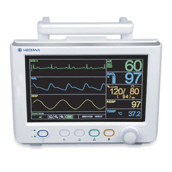
Front Panel Components Alarm indicator NIBP start/stop button Print button AC/DC indicator Home button Battery charging indicator Alarm stop button Power button Knob Figure 1. Front Panel Components... -
Page 12: Rear Panel Components
Rear Panel Components Handle AC power connector Equipotential terminal DC power connector Speaker Battery cover External communication port Figure 2. Rear Panel Components... -
Page 13: Left Panel Components
Left Panel Components Printer (option) USB port (mini USB B Type) USB port (USB A Type) Nurse call port (RJ11 Type) Figure 3. Left Panel Components... -
Page 14: Right Panel Components
Right Panel Components ECG connector connector NIBP connector Temperature connector Figure 4. Right Panel Components... -
Page 15: Routine Maintenance
(if required by your local institution). The following checks should be performed at least every year by qualified service personnel. 1. Inspect labels for legibility. If the labels are not legible, contact Mediana Technical Service Department. 2. If the monitor has been visibly damaged or subjected to mechanical shock (for example, if dropped), perform the performance tests as described in the Performance Verification section. -
Page 16: Batteries
2 year intervals. Refer to the Disassembly Guide section. Note: Due to the physical dimensions of the battery compartment, only batteries supplied by Mediana should be used. Using other types of replacement batteries may result in damage to the monitor and void the limited warranty. -
Page 17: Performance Verification
Metron QA-90 or equivalent Stopwatch Manual or electronic Note: The sphygmomanometer must be calibrated periodically. The correct value cannot be found if the sphygmomanometer has not been calibrated. Note: Contact Mediana Technical Service Department for pricing and ordering information of the required equipment. -
Page 18: Performance Tests
Performance Tests The battery charge and battery discharge test should be performed before monitor repairs whenever the battery is suspected as being a source of problems. All other tests may be used following repairs or during routine maintenance (if required by your local institution). Before performing the battery discharge test, ensure that the battery is fully charged. - Page 19 displayed about 15 minutes before battery fully discharges. 11. Allow the monitor to operate until it automatically powers down due to the low battery condition. Verify that the high priority alarm occurs and the alarm message “Critically Low-Battery condition” is displayed about 5 minutes before the monitor automatically shuts down.
-
Page 20: General Operation Tests
General Operation Tests Alarms and Alarm Audio Paused 1. Connect the monitor to an AC power source or external DC power source. 2. Press the Power Button to turn on the monitor. 3. Connect the SpO simulator to the SpO extension cable and connect the cable to the monitor. -
Page 21: Table 2. Parameter Alarm Limit Factory Defaults
pulse rate tone decreases. 10. Set QRS volume to Off and return to the monitoring screen. Verify beeping pulse rate tone is no longer audible. 11. Return QRS volume to a comfortable level. Sensor LED Test This procedure uses normal system components to test circuit operation. An SpO sensor, DS-100A is used to examine LED intensity control. - Page 22 1. Turn on the monitor under Factory default settings. 2. Select the Alarm/Limits Menu Icon to display the Alarm/Limits Menu. 3. Verify that alarm limits are set as shown in Table 2. 4. Change Patient mode in the Set-up menu from Adult to Pediatric or Neonatal, then verify that alarm limits are set as shown in Table 2.
- Page 23 8. Test #5: Print-On-Alarm Set Print-On-Alarm to ON via the Alarm/Limits Menu. Set the Heart Rate of your ECG simulator to 30bpm. Verify “Low Heart Rate/Pulse Rate limits violated” alarm is activated and the parameter values and waveforms are printed out. Note: If no printer is installed in the monitor, Print Mode, Print Speed and Print On Alarm will not display.
- Page 24 Measurement Parameter Operation Tests ECG Operation 1. Press the Power Button to turn on the monitor. 2. Connect the ECG 3 lead wires to appropriate terminals on the ECG simulator. 3. Connect lead wires to the ECG cable. 4. Connect the ECG cable to the ECG connector on the monitor’s right panel. 5.
- Page 25 NIBP Operation These tests verify the functionality of the M20 pneumatic system. The Bio-Tek simulator or any equivalent NIBP simulator is required to perform these tests. Each of the tests must be performed to verify pneumatic system functionality.
-
Page 26: Figure 5. Pressure Sensor Accuracy Test
Pressure Sensor Accuracy Test Figure 5. Pressure Sensor Accuracy Test 1. Ensure Bio-Tek simulator is in the static pressure test mode. 2. The NIBP test screen is active on the monitor, then select Pressure Sensor Accuracy Test by the knob. 3. -
Page 27: Figure 6. Air Leakage Test
Air Leakage Test Figure 6. Air Leakage Test 1. Ensure the monitor is set up with dummy can-large. 2. Ensure NIBP Test Mode screen is active on the monitor, then select Air Leakage Test by the knob. 3. The monitor displays the pressure of approximately 290 mmHg automatically. 4. -
Page 28: Figure 8. Deflation Rate Measurement
1. Ensure the monitor is set up with the dummy can-large. 2. Ensure NIBP Test screen is active on the monitor, then select “Inflation Time Measurement” by the knob. 3. The monitor displays the pressure of approximately 290 mmHg automatically and measures the inflation time in seconds. - Page 29 . The test pass criteria is 88 to 92%SpO The monitor will display: - 90%SpO - 60 bpm - no alarm For Mediana module Press the %SpO selection button on the SpO simulator. The %SpO 92 LED will light:...
- Page 30 For Mediana module Press the PULSE RATE selection button on the SpO simulator. The PULSE RATE 240 LED will light. The pulse rate will increase to 240 bpm. The test pass criteria is 238 to 242 bpm. The monitor will display:...
- Page 31 Note: The accuracy of Respiration measurements is ±3 breaths per minute. In the procedure above, add the tolerance of the simulator to the acceptable range of readings. Temperature Operation 1. Press the Power Button to turn on the monitor. 2. Connect the temperature probe (supplied with the temperature simulator) to an appropriate terminal on the temperature simulator.
-
Page 32: Safety Tests
Safety Tests The monitor safety tests meet the standards of, and are performed in accordance with, IEC 60601-1, Clause 19 (Second Edition, 1988; Amendment 1, 1991-11, Amendment 2, 1995- 03), EN60601-1 for instruments classified as Class I and Type CF. Protective Earth Continuity This test checks the integrity of the power cord ground wire from the AC plug to the instrument chassis ground. -
Page 33: Table 4. Enclosure Leakage Current
Note: The analyzer leakage current indication must not exceed the values listed in Table 4. Table 4. Enclosure Leakage Current Test Condition Allowable Leakage Current (microamps) Normal Condition (NC) SFC Open Supply (OS) SFC Open Earth (SFC OE) Normal Condition RM (NCRM) SFC Open Supply RM (SFC OSRM) SFC Open Earth RM (SFC OERM) Patient Leakage Current... -
Page 34: Table 6. Patient Leakage Current Values - Mains Voltage On Applied Part
Patient Leakage Current - Mains Voltage on the Applied Part WARNING: AC power voltage will be present on the applied part terminals during this test. Exercise caution to avoid electrical shock hazard. WARNING: Do not touch the patient leads clips or the simulator parts connected to patient leads during this test as an electrical shock will occur. -
Page 35: Table 7. Test Lead Combinations
Patient Auxiliary Current This test measures patient auxiliary current in accordance with IEC60601-1, clause 19, for Class I, type CF equipment. The applied voltage for IEC60601-1 is 264 volts, 50 to 60 Hz. Patient auxiliary current is measured between each ECG test lead and between each sensor connection for all possible connections. -
Page 36: Verification Check Sheet
- Pulse rate 200 ± 3bpm (High priority alarm condition) (for Nellcor module) Pass / Fail Value: - Pulse rate 240 ± 2bpm (High priority alarm condition) (for Mediana module) - Pulse rate 60 ± 3bpm (for Nellcor module) Pass / Fail Value: - Pulse rate 60 ±... - Page 37 SAFETY TEST TEST CONDITIONS LIMIT (uA) RESULTS REMARKS Earth leakage current (NC) Pass / Fail Value: Earth leakage current (SFC OS) 1000 Pass / Fail Value: Earth leakage current (NCRM) Pass / Fail Value: Earth leakage current (SFC OSRM) 1000 Pass / Fail Value: Enclosure leakage current (NC)
- Page 38 SAFETY TEST TEST CONDITIONS LIMIT (uA) RESULTS REMARKS Patient auxiliary current ECG LL-SpO (SFC OE) Pass / Fail Value: Patient auxiliary current ECG LL-SpO (NCRM) Pass / Fail Value: Patient auxiliary current ECG LL-SpO (SFC OSRM) Pass / Fail Value: Patient auxiliary current ECG LL-SpO (SFC OERM) Pass / Fail...
-
Page 39: Service Menu And Factory Default
SERVICE MENU AND FACTORY DEFAULT General This section discusses use of the Service menu to configure ’Save Setting On Power Off’, ‘Alarm Audio Off Period’, ‘Alarm Audio Puased Period’, ‘Alarm Reminder Tone’, ‘Alarm Audio Type’, ‘NIBP Unit’, ‘Temp Unit’, ‘Language’, ‘NIBP TEST MODE’ and ‘System Information'. -
Page 40: Figure 10. The Access Of Service Menu Via Set-Up Menu
Figure 10. The access of Service Menu via Set-up menu Note: The access code is 4, 0, 2. It is set at the factory and cannot be changed. 5. Rotate the knob to highlight the top of the digits. Press the knob to enter the Pass Code. 6. -
Page 41: Table 9. Service Menu
Table 9. Service Menu Level 1 Menu Level 2 Menu Level 3 Menu Save Setting On Power Off Custom, Back up, Default Alarm Audio Off Period OFF, 1, 3, 5, 10, 20, 30, 60 min, Indefinite (Alarm Inhibition) Alarm Audio Paused Period 30, 60, 90, 120 sec Alarm Reminder Tone OFF, 3, 10 min... - Page 42 Alarm audio Type GN924 or IEC60601-1-8 The M20 has two different Alarm audio types, called GN924 and IEC60601-1-8. They have different tone pitch and on-off beep patterns. (Refer to Alarms and Limits section in the operator’s manual) NIBP Unit The NIBP Unit can be set to mmHg or kPa.
-
Page 43: Done
NIBP TEST MODE These menus facilitate performing verification testing for the NIBP subsystem. For a detailed procedure, refer to the Performance Verification section. Table 10. NIBP Test Tests Description Pressure Sensor verifies that the pneumatic pressure sensor accuracy is Accuracy Test within the specification. -
Page 44: Factory Default Settings
Factory Default Settings Factory default settings are divided into adult, pediatric and neonatal as described in Table The patient mode is preset to “Adult” mode. Alarm limits will be automatically changed to the default settings for each patient mode as the mode is changed to Adult, Pediatric or Neonatal mode. - Page 45 Factory Defaults Parameter Ranges/Selections Adult Pediatric Neonatal NIBP MAP Upper Alarm 25 to 260 mmHg (Adult/Pediatric) Limits 3.3 to 34.6 kPa (Adult/Pediatric) 110 mmHg 90 mmHg 70 mmHg 35 to 110 mmHg (Neonatal) 14.6 kPa 12.0 kPa 9.3 kPa 4.6 to 14.6 kPa (Neonatal) (5 mmHg / 0.6 or 0.7 kPa steps) NIBP MAP Lower Alarm 20 to 255 mmHg (Adult/Pediatric)
- Page 46 Factory Defaults Parameter Ranges/Selections Adult Pediatric Neonatal 한국어 (Korean), 中文 (Chinese), English, Français (French), Deutsch (German), Italiano (Italian), 日本語 (Japanese), Português (Portuguese), Dansk (Danish), Language* English Nederlands (Dutch), Suomi (Finnish), Ελληνικά (Greek), Norsk (Norwegian), Polski (Polish), Русский (Russian), Castellano (Spanish), Svenska (Swedish), Türkçe(Turkish) Date Format* Year/Month/Day, Month/Day/Year,...
-
Page 47: Firmware Download
This section is for the purpose of reloading Firmware into the monitor when the possibility of corrupted Firmware exists, or updating Firmware with a new system revision (system/device version). Call Mediana Technical Service Department for the latest version of Firmware utility required. -
Page 48: Figure 13. Firmware Downloading Completion
USB download a. Connect a USB memory drive containing the firmware to the USB port on the left panel of the monitor. b. The monitor will automatically run the firmware download once the USB memory is detected. TCP/IP download a. Connect a LAN cable to the External communication port on the rear panel of the monitor. - Page 49 Note: When new firmware downloading is completed, the monitor still keeps the previous settings. Note: If any problem occurs during Firmware downloading, refer to Firmware Download in the Troubleshooting section.
- Page 50 This page is intentionally left blank.
-
Page 51: Troubleshooting
TROUBLESHOOTING General This section provides information that can be helpful in troubleshooting the M20 monitor. How to Use This Section If the Unit is not functioning properly, please check on the following items before calling for repair service. Use this section in conjunction with the Performance Verification section and the Spare Parts section. -
Page 52: Troubleshooting Guide
Problems with the monitor are separated into categories for further troubleshooting instructions. Note: Taking the recommended actions discussed in this section will correct the majority of problems you will encounter. However, problems not covered here can be resolved by calling Mediana Technical Service Department. Table 15. Problem Categories Categories Symptoms 1. - Page 53 1. Power Power problems are related to AC and/or Battery as follows. If the action requires replacement of the components, refer to the Disassembly Guide section. CAUTION: Electrical shock hazard. Disconnect the power cord from the monitor before attempting to open or disassemble the monitor. Symptom 1.1: Monitor will not turn on though the power button is pressed.
- Page 54 3. Sound Symptom 3.1: No sound during the POST. Cause or Checkpoint Action Remark Speaker is broken or speaker wire Reconnect the wire or replace is loose/disconnected. the speaker. Main Board is malfunctioning. Replace the Main Board. Symptom 3.2: Alarm is not silenced. Cause or Checkpoint Action Remark...
- Page 55 5. NIBP Symptom 5.1: The cuff does not inflate. Cause or Checkpoint Action Remark Cuff or Cuff hose is folded. Unfold the cuff or cuff hose. NIBP tube inside of the monitor is Check the tube assembly blocked or kinked. between NIBP module and hose fitting.
- Page 56 9. ECG Symptom 9.1: Rapid, large and erratic detections. Cause or Checkpoint Action Remark A broken wire in the patient lead Replace wire and electrode A poorly applied sensor Check artifact occurred. ECG module is broken. Replace the ECG module. Main board is broken.
-
Page 57: Table 16. Firmware Downloading Error Codes
10. Firmware Download If an error code appears during the firmware downloading, take the action specified in Table Note: If the alarm message still appears, take monitor out of service and contact Mediana Technical Service Department for advice on remedial action. - Page 58 Error codes Conditions EEE255 module invalid jumper selection EEE256 module beginning of packet missing EEE257 module packet start (SID) missing EEE258 module packet length error EEE259 module message length error EEE260 module packet contains unsupported key EEE261 module packet CRC error EEE262 module end of packet missing EEE263...
-
Page 59: Disassembly Guide
DISASSEMBLY GUIDE WARNING: Performance Verification. Do not place the monitor into operation after repair or maintenance has been performed until all Performance Tests and Safety Tests listed in the Performance Verification section of this service manual have been performed. Failure to perform all tests could result in erroneous monitor readings. -
Page 60: Figure 14. Disassembly Sequence Flow Chart
Front case assembly Rear case assembly Battery Printer Rear case Front case Alarm LED board, Alarm window LCD, LCD inverter Handle Key board Side connector cover C4-1 ECG connector Main Board C5-1 CPU board C5-2 ECG & Resp module C5-3 Temp module C5-4 module... -
Page 61: Replacement Level Supported
Replacement Level Supported The replacement level supported for this product is to the printed circuit board (PCB) and major subassembly level. Once you isolate a suspected PCB, follow the procedures in Disassembly Guide to replace the PCB with a known good PCB. Check to see if the trouble symptom persists, swap back the replacement PCB with the suspected malfunctioning PCB (the original PCB that was installed when you started trouble shooting) and continue troubleshooting as directed in this section. -
Page 62: Optional Printer Disassembly (A2)
Optional Printer Disassembly (A2) This section describes the steps that may remove an optional printer in the monitor. If you would like to install a printer, follow the reverse sequence of the procedures. Figure 16. Printer Disassembly Figure 17. Printer Disassembly - Printer Board, Printer Body Case, Printer Opener Case, Printer Door Case, Printer Mecha, Printer Door Pin, Printer Paper... -
Page 63: Table 18. Part Descriptions - Printer Board, Printer Body Case, Printer Opener Case, Printer Door Case, Printer Mecha, Printer Door Pin, Printer Paper
Table 18. Part Descriptions - Printer Board, Printer Body Case, Printer Opener Case, Printer Door Case, Printer Mecha, Printer Door Pin, Printer Paper Part Codes Descriptions A0132 Thermal printer paper (50mm) M4031 Thermal printer board T0197 Thermal printer body case T0198 Thermal printer opener case T0199... -
Page 64: Monitor Disassembly
Monitor Disassembly This section describes the steps to separate the front and rear case assemblies. Figure 18. Monitor Disassembly Table 19. Part Descriptions - Printer Cover Part Codes Descriptions B0076 Thermal printer label T0200 Thermal printer cover Before steps B and C (1) 1. -
Page 65: Figure 19. Monitor Disassembly
Figure 19. Monitor Disassembly Table 20. Part Descriptions - Front Case and Rear Case Assembly Part Codes Descriptions Front case assembly (A) Rear case assembly (B) T2017 Rear case cover T1006 Rubber foot T8045 EtCO overlay Before steps B and C (2) 1. -
Page 66: Front Case Disassembly (B)
Front Case Disassembly (B) This section describes the items that may be removed on the front case assembly. Figure 20. Front Case Disassembly - Front Case, LCD, Key Board Table 21. Part Descriptions - Front Case, LCD, Key Board Part Codes Descriptions T0207 Front case... - Page 67 B1. Front case disassembly 1. Pull the knob straight out to separate from the monitor. 2. Remove the knob body and knob grip from the knob. 3. Remove the 6 round-head screws (3×6) from the front case assembly. 4. Separate the front case from the middle case assembly. B2.
-
Page 68: Rear Case Disassembly (C)
Rear Case Disassembly (C) This section describes the items that may be removed on the rear case assembly. Figure 21. Rear Case Disassembly - Handle, Alarm LED Board, Alarm Window, Inner Case Table 22. Part Descriptions - Handle, Alarm LED Board, Alarm Window, Inner Case Part Codes Descriptions T0205... - Page 69 C1. Rear case disassembly 1. Remove 2 bind-head screws (3×6) on the rear case assembly. 2. Remove 2 round-head screws (3×6) on the inner case assembly. 3. Separate the inner case assembly from the rear case. 4. Remove the vent cover and alarm window from the rear case. C2.
-
Page 70: Figure 22. Rear Case Disassembly - Main Board, Side Connector Cover, Ecg Connector
Figure 22. Rear Case Disassembly - Main Board, Side Connector Cover, ECG Connector Table 23. Part Descriptions - Main Board, Side Connector Cover, ECG Connector Part Codes Descriptions P1105 / P1093 Main Board for Nellcor SpO module / for Mediana SpO module T0212 Side connector cover E4114 Luer fitting/NIBP connector E4231 ECG connector (6pin) C4. -
Page 71: Figure 23. Rear Case Disassembly - Ecg & Respiration Module, Spo 2 Module, Cpu Module (For Nellcor Spo 2 Module)
Figure 23. Rear Case Disassembly - ECG & Respiration Module, Module, CPU Module (For Nellcor SpO Module) Figure 24. Rear Case Disassembly - ECG & Respiration Module, Module, CPU Module (For Mediana SpO Module) Table 24. Part Descriptions - ECG & Respiration Module, SpO Module, CPU Module... - Page 72 CPU board P1099 Temperature module M0009 / P1102 Nellcor SpO module / Mediana SpO module C5-1. CPU board disassembly 1. Remove 6 round-head screws (3x4) from the CPU board and the Main Board to remove 3 supporters fastening the CPU board.
-
Page 73: Figure 25. Rear Case Disassembly - Smps, Ac Inlet, Speaker, Ecg Arrester Board, Printer Interface Board, Tcp/Ip Board, Nibp Module
Figure 25. Rear Case Disassembly - SMPS, AC Inlet, Speaker, ECG Arrester Board, Printer Interface Board, TCP/IP Board, NIBP Module Table 25. Part Descriptions - SMPS, AC Inlet, Speaker, ECG Arrester Board, Printer Interface Board, TCP/IP Board, NIBP Module Part Codes Descriptions M2024 SMPS... - Page 74 C6. SMPS disassembly 1. Remove the SMPS control cable, DC power cable, external DC cable and battery cable from the SMPS. 2. Remove 5 round-head screws (3x6) from the SMPS. 3. Separate the SMPS from the inner case. C6-1. AC inlet board disassembly 1.
-
Page 75: Figure 26. M20 Exploded View
Figure 26. M20 Exploded View... - Page 76 This page is intentionally left blank.
-
Page 77: Spare Parts
Spare parts, along with part numbers, are shown in Table 26. “Item No.” corresponds to the circled callout numbers in Figure 27. Obtaining Replacement Parts Mediana provides technical assistance information and replacement parts. To obtain replacement parts, contact Mediana Technical Service Department. Refer to parts by the part names and part numbers. -
Page 78: Figure 27. M20 Exploded View - Spare Parts
Figure 27. M20 Exploded View - Spare Parts... -
Page 79: Table 26. Spare Part List
T0211 Rear case T0221 Vent cover T4155 Battery cover P1105 Main Board (for Nellcor SpO module) P1093 Main Board (for Mediana SpO module) P1094 ECG & Respiration module P1096 ECG arrestor assembly board P1098 CPU board P1099 Temperature module M0009... - Page 80 Item Part Code Description T0210 Inner case E9021 Speaker T0209 Middle case T0201 Power / battery window T0214 Button T0224 Button ring (green) T0223 Button ring (orange) T0213 Button ring (blue) T0225 Button ring (white) M8002 LCD inverter P1095 Key assembly board T0207 Front case M4032...
-
Page 81: Packing For Shipment
Pack the monitor carefully. Failure to follow the instructions in this section may result in loss or damage not covered by the Mediana Limited Warranty. See Limited Warranty information in the M20 Instruction Manual. If the original shipping carton is not available, use another suitable carton. - Page 82 This page is intentionally left blank.
-
Page 83: Specification
SPECIFICATION Display 7” measured diagonally across the TFT-LCD screen Screen Size Screen Type/Color Liquid Crystal Display (LCD) Color, Cold Cathode Fluorescent Backlit Resolution 800 × 480 pixel Number of traces 3 waveforms Controls Knob control; Standard 5 soft buttons (Alarm Stop, NIBP Start/Stop, Home, Print, Power) Alarms Categories... - Page 84 Printer (Optional) Type Thermal Weight 150 g (.33 lb) Resolution 8 dot/mm Number of channels 1 to 2 channels Paper Type Thermal Paper Width 50 mm Pint Speeds 25 mm/s, 50 mm/s...
-
Page 85: Electrical
4, 8 or 12 hours for depleted battery to 90% of battery capacity and for full recharge with monitor turned on/off. Life Cycle 6 months, new battery fully-charged After 2 months storage the M20 would run for 50% of stated battery life. Environmental Conditions Operation Temperature 5 to 40°C (41 to 104°F) -
Page 86: Tone Definition
Tone Definition High Priority Alarm Tone Volume level Adjustable (level 1~8) 976 Hz (IEC60601-1-8, HI) Pitch (± 5%) 540 Hz (IEC60601-1-8, LOW) 976 Hz (GN924) Pulse width (± 5%) 170 msec (IEC60601-1-8), 250 msec (GN924) 10 pulses per 4 sec, 8 sec inter burst (IEC60601-1-8) Number of pulses 7 pulses per 2 sec (GN924) Repetitions... -
Page 87: Measurement Parameters
Measurement Parameters Heart Rate Measurement Range 0, 20 to 300 BPM Accuracy ±1 BPM or ±1% whichever is greater Average Response Time 3 seconds (from 80 to120 BPM) 4 seconds (from 80 to 40 BPM) ECG (Electrocardiograph) Leads 3 / 5 Lead Lead I, II, III, aV , aV , aV... - Page 88 Time to alarm for Vent Tachycardia 1 mVpp, 131 ~ 168 bpm: tachycardia Amplitude 0.5 mV: 13.28 sec Amplitude 1 mV: 15.82 sec Amplitude 2 mV: 6.34 sec Vent Tachycardia 2 mVpp, 63 ~ 128 bpm: Amplitude 1 mV: 7.92 sec Amplitude 2 mV: 7.75 sec Amplitude 4 mV: 8.39 sec Time to alarm for cardiac...
- Page 89 Respiration Respiration Technique Impedance Pneumography Range 0, 3 to 120 breaths/min Accuracy ±3 breaths/min Leads RA to LA Display Sweep Speeds 6.25 mm/s, 12.5 mm/s, 25.0 mm/s Lead Off Condition Detected and displayed Display Size 10 mm/ohm (×1) Wave Size Auto, Level 1~8 Defibrillator Protection Protected...
- Page 90 20 to 300 BPM Mediana module: 30 to 254 BPM Accuracy Nellcor module: 20 to 250 beats per minute (bpm) ±3 digits Mediana module: ±2% or 2BPM, whichever is greater Range Nellcor module: 1 to 100 % Mediana module: 0 to 99 % Low Perfusion 0.03 to 20 %...
- Page 91 Neonatal specifications are shown for neonatal sensors with the monitor. Saturation accuracy will vary by sensor type as specified by the manufacturer. Note: The wavelength range of the light emitted are near 660 nm and 890 nm with the energy not exceeding 15mW.
-
Page 92: Trends
Temperature Thermistor Temp Probe Type Thermistor probe YSI 400 series and 700 series Measurement Method Thermistor Range 0 to 50°C (32 to 122°F) Display Accuracy ±0.1°C Probe Accuracy YSI 400 series and YSI 700 series Probes: ±0.1°C from 25 to 45°C, ±0.2°C from 0 to 25°C and from 45 to 50°C Defibrillator Protection Protected... -
Page 93: Compliance
Compliance Item Standard Description Classification IEC60601-1:2005, Class I (on AC power) EN60601- Internally powered (on battery power) 1:2006/AC:2010 Type CF – Applied part Type of protection IEC60601-1:2005, EN60601- 1:2006/AC:2010 Mode of operation IEC60601-1:2005, Continuous EN60601- 1:2006/AC:2010 Degree of protection IEC 60529:1989 IPX1 (provided by enclosures) +A1:1999 +A2:2013, EN 60529:1991... - Page 94 Item Standard Description IEC60601-1-6:2010, Medical electrical equipment - Part 1-6: General EN60601-1-6:2010 requirements for basic safety and essential performance - Collateral standard: Usability IEC62366:2007, Medical devices - Application of usability EN62366:2008 engineering to Medical devices Biological evaluation of medical devices – Part 1: ISO10993-1:2009 /Cor1:2010, Evaluation and testing...
- Page 95 Item Standard Description IEC61000-4-2:2008, Electrostatic discharge Ed 2.0 EN61000-4-2:2009 IEC61000-4-3:2006 Radiated RF electromagnetic field Ed 3.1 +A1:2007+A2:2010, EN61000-4-3:2006 +A1:2008+A2:2010 IEC61000-4-4:2012, Electrical fast transient/burst Ed 2.0 EN61000-4-4:2012 IEC61000-4-5:2014, Surge current Ed 2.0 EN61000-4-5:2014 IEC61000-4-6:2013, Conducted disturbances, induced by RF field Ed EN61000-4-6:2014 IEC61000-4-8:2009, Power frequency (50/60Hz) magnetic field Ed 2.0...
- Page 96 Item Standard Description ISO15223-2:2010 Symbols to be used with medical device labels, labelling, and information to be supplied -- Part2: Symbol development, selection and validation ISO7000:2014 Graphical symbols for use on equipment-index and synopsis EN980:2008 Graphical symbols for use in the labeling of medical devices EN50419:2006 Marking of electrical and electronic equipment in...
-
Page 97: System Processing
SYSTEM PROCESSING System Overview The M20 monitor is a multi-function monitor for use on adult, pediatric and neonatal patients; ECG, heart rate, noninvasive blood pressures, arterial oxygen saturation, pulse rate, respiration rate and temperature. In addition to monitoring and displaying the status of these physiological parameters, the instrument performs various microprocessor-programmed analytical functions;... -
Page 98: Figure 29. Power Unit Block Diagram
Unit Description Power unit: consists of SMPS and battery charger AC 100 -240V Vout AC-DC 50/60Hz 10V~15V 2A DC/DC on,off V Stanby Li-ion Battery Charging LED Charger 3S1P/2200mA FUSE Charged LED 3S2P/4400mA 3S3P/6600mA AC Detect Ex-DC Detect Battery Detect Ex-DC EXTERNAL DC FUSE... -
Page 99: Figure 31. User-Control Unit Block Diagram
User-control unit: consists of knob, 5 functional buttons, optical encoder, AC/D indicator LED, Battery charging indicator LED and battery charging status indicator LED. Figure 31. User-Control Unit Block Diagram Sound unit: consists of S3C2440A, ARM CPU, 2-channel amplifiers and speaker. Alarm sound Interface Audio Amplifier... -
Page 100: Figure 34. Gui Unit Block Diagram
internal LCD controller. Figure 34. GUI Unit Block Diagram Thermal Printer unit: prints data records. Figure 35. Thermal Printer Unit Block Diagram NIBP unit: measures non-invasive blood pressure data. Figure 36. NIBP Unit Block Diagram... -
Page 101: Figure 37. Ecg Unit Block Diagram
ECG unit: measures electrocardiographic waveform data. +11Vdc ±1Vdc Isolation Regulator Regulator DC/DC +2.5V Lead off Detection Patient Isolation Pacepulse Pace Pulse Lead off detection detection detection Saturation Photo UART detection coupler Protection Differential Amplifier Amplifier Patient Cable Lead Circuit amplifier &... -
Page 102: Figure 40. Temperature Unit Block Diagram
Temperature unit: measures temperature data. Figure 40. Temperature Unit Block Diagram... -
Page 103: Ecg Processing
ECG Processing The measurement of the skin surfaces electrocardiogram is based on the electrical signals on the skin surface, produced as the heart muscle contracts and relaxes. The signals are detected by electrodes placed on the patient’s body. The information on heart activity carried by these signals varies with the placing of the electrodes. - Page 104 ● Oscillometric Response (Pressure Pulses) Distole Systole TIME Systole ● Cuff Pressure Distole TIME Overall Accuracy Discussion Overall system accuracy shall be determined by considering various influences of the pressure sensor accuracy, motion artifacts, other artifacts created by the pressure valve, technical errors of electrical components, and the origin error of oscillometric method.
-
Page 105: Spo Processing
SYSTOLIC PRESSURE Mean difference(MD): 0 mmHg Standard deviation(SD): 6 mmHg mean + 2 SD mean mean - 2 SD Average of test and reference methods (mmHg) (EXAMPLE) Agreement between test and reference methods for systolic pressure. Hypothetical data Processing Pulse oximetry works by applying a sensor to a pulsating arteriolar vascular bed. The sensor contains a dual light source and photodetector. -
Page 106: Figure 41. Oxyhemoglobin Dissociation Curve
Accuracy (Nellcor module) The saturation (SpO ) accuracy specification and/or pulse rate (PR) performance were analyzed by comparative oximetry performance (COPS) tests between M20 SpO module ® and MP506 module with the same version of the oximetry algorithm from Nellcor... -
Page 107: Respiration Processing
Accuracy (Mediana module) The saturation (SpO ) accuracy specification was proven by comparisons with the arterial blood gas measurements. Statistically significant number of samples at SpO levels ranging from 70% to 99% was collected on male and female volunteers, with different skin colors. -
Page 108: Temperature Processing
The M20 monitor is designed to accept the signals from a range of temperature probes from the YSI-400 and YSI-700 series. The probes may be used for skin or rectal temperature measurement.
Need help?
Do you have a question about the M20 and is the answer not in the manual?
Questions and answers