
Summary of Contents for Agito AGD155
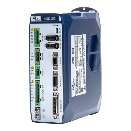
- Page 1 General Description AGD155 Standalone 240 VAC Drive Product Manual AGD155 Product Manual Rev.2.2 Page 1...
- Page 2 Agito Akribis Systems Ltd. Products Rights AGDx, AGCx, AGMx, AGAx, AGIx, and AGLx are products designed by Agito Akribis Systems Ltd. in Israel. Sales of the products are licensed to Akribis Systems Pte Ltd. under intercompany license agreement.
-
Page 3: Table Of Contents
Safety Guidelines _______________________________________________________________ 11 Compliance ____________________________________________________________________ 12 Installation ___________________________________________________________ 13 Unpacking and Packing ___________________________________________________________ 13 Mounting _____________________________________________________________________ 13 3.2.1 Mounting the AGD155 ____________________________________________________ 13 3.2.2 Mounting Multiple Power Amplifiers ________________________________________ 14 Electrical Installation ____________________________________________________________ 15 3.3.1 Power Wiring ___________________________________________________________ 15 Regeneration ____________________________________________________________ 15 3.3.2... - Page 4 Commissioning __________________________________________________________ 49 4.3.2 Current Loop Tuning ______________________________________________________ 50 4.3.3 Auto Velocity and Position Loop Tuning ______________________________________ 51 4.3.4 Manual Velocity and Position Loop Tuning ____________________________________ 54 Maintenance and Servicing ______________________________________________ 56 Troubleshooting ________________________________________________________________ 56 AGD155 Product Manual Rev.2.2 Page 4...
-
Page 5: Product Description
The AGD155 can drive various types of motors, such as voice coil, brushed, and brushless, including direct-drive linear and rotary motors. AGD155 can also synchronize with other axes in an Ethernet, CAN, and RS485 networks. -
Page 6: System Design
Output power @ 240 VAC 0.72 kVA 1.44 kVA 2.4 kVA Input current @ 1-phase 120-240 VAC 4.5 A 15 A Input current @ 3-phase 208 VAC 10 A Peak current time 1.5 sec AGD155 Product Manual Rev.2.2 Page 6... - Page 7 Commutation: Auto-phasing, Hall sensors Sin/Cos encoder Hardware: Differential RS422/RS485, 1V pkp @2.5V (available on Main Encoder port only) Max. input frequency: 250 kHz Termination: 120 Ω Max interpolation: 13 bits (x 8192) Commutation: Auto-phasing, Hall sensors AGD155 Product Manual Rev.2.2 Page 7...
- Page 8 Bi direction differential I/O Hardware: Differential RS422 Termination: 120 Ω Propagation delay: 100 ns Max. frequency: 5 MHz Direction: Input or output, set by Agito PCSuite Functionality: Any differential input or output functionality. AGD155 Product Manual Rev.2.2 Page 8...
- Page 9 Feature Specification Unit dimensions (max) H=196.97 mm, W=65.80 mm, D=158.60 mm Package dimensions 244 mm x 92 mm x 198 mm Unit weight 1.29 kg Shipping weight 1.44 kg Figure 3. Product Dimensions (mm) AGD155 Product Manual Rev.2.2 Page 9...
-
Page 10: Environmental Specifications
Environmental Specifications 1.5 Environmental Specifications Environmental Specifications Feature Specification Operating temperature* AGD155-xx-2A03: 0°C to 50°C AGD155-xx-2A06: 0°C to 50°C AGD155-xx-2A10: 0°C to 40°C Storage temperature -20°C to 70°C Operating humidity < 90% Storage humidity < 40% Pollution degree Vibration 1G @ 150 Hz according to IEC 60068-2-6... -
Page 11: Safety
Attention All power connectors must be securely tightened before any operation. Warning Connectors X10, X9, and X7 are high power. Do not touch these connectors when the product is powered. AGD155 Product Manual Rev.2.2 Page 11... -
Page 12: Compliance
It is the responsibility of the machine or end-product manufacturer to ensure the final machine or end-product meets the requirement of any safety and EMC regulations. AGD155 Product Manual Rev.2.2 Page 12... -
Page 13: Installation
3.2.1 Mounting the AGD155 The heatsink on the back of the AGD155 includes a hole (at top) and a slot (at bottom) for mounting the unit. The AGD155 must be mounted vertically (book mounting), as shown in Figure 3. The AGD155 is mounted using 2 M4 screws. It is important to mount the product on metal panel for both grounding and secure connections. -
Page 14: Mounting Multiple Power Amplifiers
If amplifiers are mounted on a backplane, the backplane temperature must not exceed the limit defined section Safe Operating Area (SOA). It is recommended to install a cooling fan at the bottom of the cabinet for best circulation. Figure 4. Mounting multiple amplifiers within cabinet AGD155 Product Manual Rev.2.2 Page 14... -
Page 15: Electrical Installation
3.3.1 Power Wiring AGD155 is designed to operate directly from 110 VAC to 240 VAC mains power, which is supplied to bus voltage, to motor, and to logic power. Logic power input (L1C, L2C) uses 1-phase 120 VAC to 240 VAC input. -
Page 16: Circuit Breakers
Circuit breaker type Type C. 2-pole for L to N. 3-pole for 3-phase. Fuse type Time delay / slow blow Current rating AGD155 10A: 25 A AGD155 6A: 10 A AGD155 3A: 6 A Voltage rating AC 600 VAC Interrupt rating... -
Page 17: Safe Operating Area (Soa)
A motor-enable request will create an error if PwrTemp is higher than 80°C. The following figure shows examples of safe operating cases for AGD155-xx-2A06. The SOA charts assume 90% duty cycle on PWM output continuously; that is, motors are moving at the maximum speed allowed by the bus voltage. -
Page 18: Grounding
3.3.5 Grounding It is recommended to install the AGD155 on a metal plate for better power dissipation, reduced EMI, and grounding connection. Make sure the plate is not painted. The heatsink of the AGD155 is electrically conductive and serves as the protective earth (PE) ground of the product. -
Page 19: Grounding Policy
The enclosures and other external parts that may be touched by the user are in the safe domain. The AGD155 must be connected to protective earth (PE) and connected to the building’s ground. PE is protected with an earth-leakage circuit breaker (ELCB); hence it is safe to touch. Refer to Figure 7. -
Page 20: Electrical Interfaces
Plug or unplug the power connector only when power is off and after the bus LED has turned off (red LED visible at the side of the product). Plugging the power connector when power is on may cause power surges through connected devices and possibly damage them. AGD155 Product Manual Rev.2.2 Page 20... -
Page 21: Interface X14: I/O And Brake Power
Warning - Hot plugging is forbidden! Plug or unplug the power connector only when power is off! Plugging the power connector when power is on may cause power surges through connected devices and possibly damage them. AGD155 Product Manual Rev.2.2 Page 21... -
Page 22: Interface X7: Motor
Connector X7: MOTOR (Brushed or Voice Coil Motor) Pin # Name Description Motor Phase + Positive terminal, phase A or M1 Motor Phase - Negative terminal, phase B or M2 Do not connect Protective earth (motor power cable shield) AGD155 Product Manual Rev.2.2 Page 22... -
Page 23: Interface X15: Safety
Safety_Feedback positive (collector) output Safety_Input_2+ Safety_Input_2 positive input Safety_Input_1+ Safety_Input_1 positive input Connector manufacturer Samtec Inc. Mating connector part number IPD1-04-D-K Crimp contact part number CCC79L-2630-01-L (or equivalent) Wiring 26 AWG, insulation rated for 100 V AGD155 Product Manual Rev.2.2 Page 23... -
Page 24: Safety Circuitry
The electrical characteristics of Safety_Input_1 and Safety_Input_2 are identical to those of all other discrete, isolated inputs of the controller. The safety inputs implemented in the product are currently pending certification Functional Safety Standards. AGD155 Product Manual Rev.2.2 Page 24... -
Page 25: Interface X8: Static Brake
Protective earth Connector manufacturer Phoenix Contact Mating connector part number 1942497 (Wurth Electronics equivalent: 691340500003) (Degson equivalent: 2EDGKDM-5.08-3P-14) Connector pitch 5.08 mm Wiring 18-20 AWG,insulation rated for 100 V Brake Circuitry Figure 14. Static brake AGD155 Product Manual Rev.2.2 Page 25... -
Page 26: Interface X9: Regeneration
There are no current or power protections to protect the regeneration resistor or the internal MOSFET. Be sure to set the suitable regeneration parameters for the supply voltage and the external regeneration resistor. AGD155 Product Manual Rev.2.2 Page 26... - Page 27 We recommend adding external protections (such as PTC) to protect the regeneration resistor. AGD155 Product Manual Rev.2.2 Page 27...
-
Page 28: Dip Switches
3.4.7 DIP Switches The AGD155 includes 8 DIP switches to define CAN or Ethernet address offset, to connect a 120Ω CAN terminator resistor, to activate firmware download mode, and set other functions. These are hardware configurations that are typically done only once, during product installation. -
Page 29: Interface X13: Ethernet (Lan)
BI-_D4 Bi-directional - Connector type RJ45 LAN 10/100Base-T connector Mating connector part number Any CAT5e compatible shielded connector Cable CAT5e or higher, standard Ethernet straight cable Wiring 26 AWG, insulation rated for 100 V AGD155 Product Manual Rev.2.2 Page 29... -
Page 30: Interfaces X11, X12: Can Bus, Rs232 And Rs485
CAN bus chain. The RS485 lines have a built-in (not optional) 120Ω terminator. Communication performance may be degraded if too many units are placed on the RS485 chain. AGD155 Product Manual Rev.2.2 Page 30... -
Page 31: Interface X1: Micro Usb
USB to RS232 bridge The Micro-USB connection is implemented using an internal converter/adapter from USB to RS232 (UART). Typically, the Windows OS contains a built-in driver for the convertor/adapter. If necessary, you can access drivers at: http://www.ftdichip.com/Drivers/D2XX.htm. AGD155 Product Manual Rev.2.2 Page 31... -
Page 32: Interface X2: Main Encoder
This port supports digital quadrature incremental encoders (AqB), analog sin/cos incremental encoders, absolute BiSS-C encoders, and absolute EnDat2.2 encoders. The type of encoder connected to the AGD155 is configured in the Agito PCSuite software. Figure 20. Main Encoder Connector... -
Page 33: Interface X3: Auxiliary Encoder
Encoder_3+ B+ B+ (for AqB) Encoder_3- B- B- (for AqB) Encoder_4+ Z+ DATA+ DATA+ Data+ for absolute encoders, or Z+ for AqB Encoder_4- Z- DATA- DATA- Data- for absolute encoders, or Z- for AqB AGD155 Product Manual Rev.2.2 Page 33... -
Page 34: Interface X4: Hall Sensors
1 to 3 for Hall sensors. GND for 5V PT1000_EN For PT1000 temperature sensor, this pin is shorted to pin 6 (GND). For PT100 temperature sensor, this pin is not connected. AGD155 Product Manual Rev.2.2 Page 34... - Page 35 Isolated digital input 1 (NPN or PNP, depending on connection of the common pin of this group). To use as Hall input, go to the Agito PCSuite Digital Input page, and configure as Hall A. The following inputs (2 and 3) will be set automatically as Hall B and Hall C.
-
Page 36: Interface X5: System I/O
Common pin (power or return, depending on external connection) for digital input 5 to 9 Digital_Input_13 DInPort.Bit(12) Isolated digital input 13 (NPN or PNP, depending on connection of the common pin of this group) AGD155 Product Manual Rev.2.2 Page 36... -
Page 37: Interface X6: Control I/O
The Control I/O port includes a typical set of I/Os (digital isolated, fast differential, and analog) for operation with an external controller by means of ±10V analog commands or digital pulse and direction commands. Figure 24: Control I/O Connector AGD155 Product Manual Rev.2.2 Page 37... - Page 38 Differential_Input_1+ follower A+ | Handwheel A+ Differential_Input_1- Differential input 1-; | Pulse input- | Encoder follower A- | Handwheel A- Differential_Input_3+ DInPort.Bit(18) Differential input 3+ Differential_Input_3- Differential input 3- GND for the differential I/Os AGD155 Product Manual Rev.2.2 Page 38...
- Page 39 To maintain output high voltage at > 4.5V, limit the current to 60 mA. Note – 5V Digital_Output_Common_Power source mode limitation. AGD155 Differential Input_X- and Differential_Output_X- are not GND. They must be connected to the negative (-) side of a differential pair in the customer’s machine electronics.
-
Page 40: I/O Interfaces - Circuitry
Digital_Input_Common pin. Isolated Digital Input 4 Figure 26. Digital Input 4 Digital_Input_4 is internally pulled to IO_PWR_Return. It can only be connected as sinking input. AGD155 Product Manual Rev.2.2 Page 40... -
Page 41: Isolated Digital Outputs 1 To 2, And 3 To 6
250 mA) can be driven. However, the output high voltage will drop significantly. To maintain output high voltage at > 4.5V, limit the current to 60 mA. Differential Inputs 1 to 3 Figure 28. Differential Inputs 1 to 3 AGD155 Product Manual Rev.2.2 Page 41... -
Page 42: Differential Outputs 1 To 4
The bi-directional differential output is configurable by software to be differential output or differential input. Both + and - pins are pulled up to 3.3V. There is a 120Ω termination resistor between the + and - pins. AGD155 Product Manual Rev.2.2 Page 42... -
Page 43: Analog Inputs 1 To 2
Analog output reflects the internal value of a user selected parameter (position, position error, velocity, current, or any parameter/status of the controller), with a user defined scaling factor, for easy monitoring using an external oscilloscope. AGD155 Product Manual Rev.2.2 Page 43... -
Page 44: Operation
Electrical Interfaces section. Make sure the safety port is connected before any operation. 2. Open Agito PCSuite software. Select CFG in CONFIG below and setup the parameters as follows: Figure 33. Configuration Figure 34. Operation Mode Configuration 3. - Page 45 Figure 37. Position and Velocity Protection 6. Click Next to configure current and voltage limits. It is important to refer to motor’s specifications. The limits entered here must be within the motor operating limits to avoid damaging the motor. AGD155 Product Manual Rev.2.2 Page 45...
-
Page 46: Drive/Motor Overload Protection
Drive/Motor Overload Protection Figure 38. Current and Voltage Protection 4.2 Drive/Motor Overload Protection The following methods are used to protect the AGD155 from overload: Motor stuck Motor temperature protection using a PT100 or PT1000. 4.2.1 T Over Load protection In a transient condition, the motor can sustain a certain amount of energy that exceeds the continuous limit. - Page 47 Drive/Motor Overload Protection Figure 39. I In Agito PCSuite, the following parameters define the ���� ���� characteristics: Peak current Continuous current Peak time Figure 40. I T Settings Note – The I2T algorithm does not support thermal memory protection or thermal memory during power loss.
-
Page 48: Motor Stuck
4.2.3 Motor Temperature Protection If the motor temperature sensor option is selected, the AGD155 will monitor the PT100/1000 temperature sensor readings, and display warnings in the status window if the temperature is approaching the specified limit. -
Page 49: Tuning
1. Connect Hall sensors to HALLS port and configure the first of the three inputs in the digital I/O page as Hall A. 2. Use the Jump to zero phase method to establish the motor and Hall phases; select Perform learn process and click Perform Auto-Phasing. AGD155 Product Manual Rev.2.2 Page 49... -
Page 50: Current Loop Tuning
Click Calculate PI to calculate the current loop gains. Check both checkboxes for auto data recording and user predefined data recording. Click Apply Current Command to test the current loop performance. Figure 46. Current Loop Tuning AGD155 Product Manual Rev.2.2 Page 50... -
Page 51: Auto Velocity And Position Loop Tuning
Click Begin Identification to perform system identification. Figure 48. Begin System Identification When the identification is completed successfully, the plant’s transfer function will be displayed, as shown in the following figure. Figure 49. Typical Plant Transfer Function AGD155 Product Manual Rev.2.2 Page 51... - Page 52 PIV gains for this plant. Figure 51. Start Auto-Tuning calculation 4. Once Auto-Tuning is completed, click Write to Controller to download the calculated gains into the controller. Figure 52. Download the parameters to the controller AGD155 Product Manual Rev.2.2 Page 52...
- Page 53 5. Check the motion performance in the Motions Tab, set the required motion profile, and click Go 1 or Go 2 to move to Target 1 or Target 2. Record the motion data to analyze the motion performance in detail. Figure 53. Testing Motion AGD155 Product Manual Rev.2.2 Page 53...
-
Page 54: Manual Velocity And Position Loop Tuning
Figure 54. Manual Velocity Loop Tuning Figure 55. Typical Velocity Loop Performance Similarly, adjust proportional gain of position loop. In addition, adjust acceleration and velocity feedforward to improve performance. Click Apply Pos Command to check performance. AGD155 Product Manual Rev.2.2 Page 54... - Page 55 Figure 57. Typical Position Loop performance Repeat the configuration and tuning steps for all the axes connected to the product. Finally, test the motion according to the required motion profile, as shown in Figure 53. Testing Motion. AGD155 Product Manual Rev.2.2 Page 55...
-
Page 56: Maintenance And Servicing
(free wheel) Position feedback sensor is Go to Agito PCSuite’s CONFIG > FDBK page, toggle configured in wrong direction the Invert direction setting. Encoder signal is interfered Verify if the encoder signal is drifting even when the by EMI noise in the system, motor is physically locked or not moving. - Page 57 Check software position limits and velocity limits at Agito PCSuite’s CONFIG > POS page. If the FLS or RLS signal is active when the digital input is changed, the FLS or RLS status will remain ON. In this case, set the...
Need help?
Do you have a question about the AGD155 and is the answer not in the manual?
Questions and answers