Advertisement
Quick Links
Advertisement

Related Manuals for Fulton Hogan ESTOP

Summary of Contents for Fulton Hogan ESTOP
- Page 1 Version: 7.3 NZ Version: 7.0 NZ Dated: 18-11-19 Dated: 25-09-19 Fulton Hogan Signs & Graphics | signs@fultonhogan.com | P: 0800 274 463 Page | 1 Fulton Hogan Signs & Graphics | signs@fultonhogan.com | P: 0800 274 463 Page | 1...
- Page 2 Cnr Foremans & Halswell Junction Rds Hornby, Christchurch PH: 0800 274 463 Email: signs@fultonhogan.com Fulton Hogan Signs & Graphics | signs@fultonhogan.com | P: 0800 274 463 Page | 2 Fulton Hogan Signs & Graphics | signs@fultonhogan.com | P: 0800 274 463 Page | 2...
-
Page 3: Table Of Contents
LED indicators ............................13 Modes of Operations ..........................13 Operational Steps .............................14 Pairing the eSTOP™ Handheld Remote Controller (HRC) to lantern units ............15 User manual – eSTOP DVR camera system ......................17 Batteries - Care, Safe Handling and Charging ....................21 Maintenance of the eSTOP™ ..........................23 Troubleshooting ...............................23... -
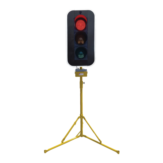
Page 4: Estop™ System Components Diagram
Centre column Adjustable locking column Locking pin Figure 1 Legs Fulton Hogan Signs & Graphics | signs@fultonhogan.com | P: 0800 274 463 Page | 4 Fulton Hogan Signs & Graphics | signs@fultonhogan.com | P: 0800 274 463 Page | 4... - Page 5 User and Service & Operation Manuals 10. 2 target boards (Applicable model only) Fulton Hogan Signs & Graphics | signs@fultonhogan.com | P: 0800 274 463 Page | 5 Fulton Hogan Signs & Graphics | signs@fultonhogan.com | P: 0800 274 463...
- Page 6 The eSTOP™ shall be installed in a suitable location clear of obstructions. An appropriate risk assessment shall be conducted to ensure the safe and suitable use of the eSTOP™. Examples of factors to consider when assessing suitable location are: a safe distance from the traffic path, so that wide loads or turning vehicles will not impact the unit, length of worksite, volume of traffic and topography.
-
Page 7: Hand Remote Controller - Hrc
Lantern width: 270 mm Lantern depth: 170 mm Target Board: 562x1063mm Fulton Hogan Signs & Graphics | signs@fultonhogan.com | P: 0800 274 463 Page | 7 Fulton Hogan Signs & Graphics | signs@fultonhogan.com | P: 0800 274 463 Page | 7... - Page 8 Charge rate: ~0.6A Battery Charging Time: 4-6 hours from low battery Fulton Hogan Signs & Graphics | signs@fultonhogan.com | P: 0800 274 463 Page | 8 Fulton Hogan Signs & Graphics | signs@fultonhogan.com | P: 0800 274 463 Page | 8...
- Page 9 The eSTOP™ is the first Electronic Single Traffic Operator Portable system of its kind. Designed to remove the operators from the hazard zone, the key features of the eSTOP™ system are: Operators can operate from a safe distance (up to 400m with option to increase distance from ...
- Page 10 Hand Remote Control once pushed in place. IMPORTANT: ensure eSTOP™ is stable and is weighted down with sandbags prior to operation. One sand bag per tripod leg is required. Fulton Hogan Signs & Graphics | signs@fultonhogan.com | P: 0800 274 463 Page | 10 Fulton Hogan Signs &...
- Page 11 Fulton Hogan Signs & Graphics | signs@fultonhogan.com | P: 0800 274 463 Page | 10 IMPORTANT NOTE Ensure eSTOP™ is stable and is weighted down with sandbags prior to operation.
- Page 12 Note: Ensure front facing camera (if applicable) is adjusted to be above the target board Fulton Hogan Signs & Graphics | signs@fultonhogan.com | P: 0800 274 463 Page | 12...
- Page 13 2.5m centres - less than 65km/h RS1/TG1 RS1/TG1 5m centres - more than 65km/h 9. The T144 30km/h AHEAD sign is optional T1A/T144 Fulton Hogan Signs & Graphics | signs@fultonhogan.com | P: 0800 274 463 Page | 13...
- Page 14 This switch will turn off the lantern instantaneously as required. Must also be switched off when not in use. Note: When setting up the eSTOP™, the lanterns shall face away from motorists until the unit is activated for use to control traffic (Operation Mode).
-
Page 15: Led Indicators
Operation Mode. During this Mode, the operations of a Typical Traffic Signal can be controlled, where the lantern can be controlled to STOP (go to Red) or GO (go to Green). Fulton Hogan Signs & Graphics | signs@fultonhogan.com | P: 0800 274 463 Page | 13 Fulton Hogan Signs &... -
Page 16: Operational Steps
3. Test - When first powered on, the HRC will starts in Test Mode and the Status Indicator ❿will show blue. During Test Mode the HRC can be used to pair to a specific eSTOP™ unit (Refer to Pairing section). If the HRC is paired to an eSTOP™ unit the Fault Indicator ❽❾... - Page 17 NZ eSTOP™ Operations & Service Manual The eSTOP™ HRC can be paired to any eSTOP™ lantern units. Once a lantern unit is paired to a HRC it is stored in memory, they will be automatically synced when powered up and ready for operation.
- Page 18 1 lantern can be Green at a time, if pairing as single unit operations, only paired to Unit1 on each HRC with each eSTOP™. Unit2 on HRC is not used. Fulton Hogan Signs & Graphics | signs@fultonhogan.com | P: 0800 274 463 Page | 16 Fulton Hogan Signs &...
- Page 19 Figure 1. eSTOP Camera and DVR Recording The eSTOP DVR is set up to record automatically when the eSTOP traffic light powers on. There is a 1 minute delay for the DVR to complete startup and start recording. A Green light under SD status indicates the DVR is recording.
- Page 20 Adjusting Camera Angle Figure 2. Camera rotations Depending on where the eSTOP is placed, the camera can be rotated horizontally and vertically to suit viewing angle of the traffic. Using a LCD and DVR video output Figure 3.
- Page 21 DVR (a right-click to enter the settings menu). Time stamp The DVR has an internal battery to keep time in track when eSTOP power is off. The time should be adjust to the local time by entering the settings menu.
- Page 22 Right click on the line to set starting and end point of the clip. Then right click in between the 2 points to back up the clip as AVI format. Fulton Hogan Signs & Graphics | signs@fultonhogan.com | P: 0800 274 463 Page | 20 Fulton Hogan Signs &...
- Page 23 Charging the Batteries 1. The HRC Battery The HRC can be charged from any USB device including the one attached to the eSTOP™ unit base (the screw cap and USB connection are located at the base of the eSTOP™). When the HRC is switched off and the USB is attached to a charging device a red charge light indicates that the battery is being charged.
- Page 24 NZ eSTOP™ Operations & Service Manual 2. The eSTOP™ Lantern The status of the eSTOP™ unit battery can be determined when the system is in test mode and the eSTOP™ unit is synced to the HRC. By pressing the stop button ❺...
- Page 25 Lantern – Assuming battery is not low. In the event of unknown error or faults, soft reset the eSTOP™ lantern by powering it off and on again. The power switch is located on the bottom of the eSTOP™ unit.
- Page 26 NZ eSTOP™ Operations & Service Manual All repairs and servicing of the eSTOP™ shall be performed by ArrowES or its authorised service center. Any services/repairs/modification or use of parts not approved by ArrowES voids any warranty and may affect the safe performance of the eSTOP™.
- Page 27 Cnr Foremans & Halswell Junction Rds Hornby, Christchurch Date: PH: 0800 274 463 Email: signs@fultonhogan.com Fulton Hogan Signs & Graphics | signs@fultonhogan.com | P: 0800 274 463 Page | 25 Fulton Hogan Signs & Graphics | signs@fultonhogan.com | P: 0800 274 463 Page | 27...
Need help?
Do you have a question about the ESTOP and is the answer not in the manual?
Questions and answers