
Subscribe to Our Youtube Channel
Related Manuals for Citizen IF1-EFX1


Summary of Contents for Citizen IF1-EFX1
- Page 1 IF1-EFX1 / IF1-EFX2 IF2-EFX1 / IF2-EFX2 Ethernet Interface Board User’s Manual Ver.2.00 Target firmware V1.15 or later (IFx-EFX1), V2.30 or later (IFx-EFX2)
-
Page 2: Table Of Contents
Contents Contents ........................2 Read before using ......................4 1. Introduction ......................7 1-1. Features ..........................7 1-2. Model Classification ......................8 1-3. Specifications ........................8 1-4. Part Names and Functions ....................9 2. Preparation ......................10 2-1. Connecting LAN cable ..................... 10 2-2. - Page 3 Contents 6-2-1. Media Converter ........................ 40 6-2-2. XML Print .......................... 40 6-2-3. XML Device Control ......................40 6-2-4. XML Device Control / Line Display .................. 41 6-2-5. XML Device Control / Scanner ..................41 6-2-6. XML Device Control / Speaker ..................41 6-2-7.
-
Page 4: Read Before Using
・ Microsoft, Windows 7, Windows 8 and Windows 10 are registered trademarks of Microsoft Corporation U.S.A. ・ CITIZEN is a registered trademark of Citizen Watch Co., Ltd. ・ Other company names and product names mentioned here are trademarks or registered trademarks of those companies. - Page 5 Network board configuration with XML data * XML Config (JavaScript) - Config SDK(JavaScript) - CITIZEN XML Device Control Service JavaScript Device Control SDK Programming Manual Peripheral device control using XML data * XML Device 【JavaScript】 - Device Control SDK (JavaScript)
- Page 6 Term Description Since different documents are intended for different audiences and assume different levels of expertise, different terms may be applied for clarity even when the content being explained is the same. In addition, some terms are easily confused because they are sometimes referred to from the opposite standpoint depending on their function.
-
Page 7: Introduction
Thank you for purchasing the Citizen IF1-EFX1/EFX2, IF2-EFX1/EFX2 Ethernet (LAN) interface board. By using the LAN interface board IF1-EFX1/EFX2, IF2-EFX1/EFX2 (hereinafter referred to as the interface board, this interface board or this board) with our POS printers and barcode printers, each printer can be directly connected to the network enabling printing from a PC on the network to the printer. -
Page 8: Model Classification
Protocols TCP, UDP, HTTP, HTTPS, ICMP, DHCP, SNMP Port number for printing RAW (port 9100 (Changeable)), LPR IP address setting Manual, DHCP Hardware IF1-EFX1 / IF1-EFX2 IF2-EFX1 / IF2-EFX2 CT-D151/E651/S251/751 Hardware Compatible printers CT-S801(II) / 851(II) / 601(II) / 651(II) -
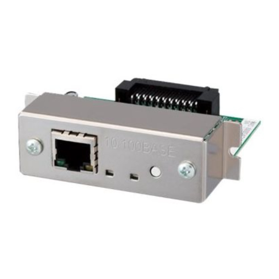
Page 9: Part Names And Functions
2 Introduction Part Names and Functions 1-4. IF1-EFX1 (No USB Port) IF1-EFX2 (USB 2 Port) ① ⑥ ① ⑦ ⑧ 10/100BAS 10/100BAS ② ② ③ ④ ⑤ ⑥ ③ ④ ⑤ IF2-EFX1 (No USB Port) IF2-EFX2 (USB 2 Port) ①... -
Page 10: Preparation
2. Preparation Connecting LAN cable 2-1. Connect a LAN cable to the RJ45 connector of RJ45 connector this interface board. (Diagram on right shows a typical example) Network cable LAN cable Connecting a Peripheral Device 2-2. The following restrictions apply to peripheral devices. Please use them properly. •... -
Page 11: Connecting The Interface Board Unit
2 Preparation 2-3. Connecting the Interface Board Unit 1) The interface board can be used by connecting it to the main board of the printer. It is connected by plugging the printer interface connector into the connector on the printer's main board. - Page 12 2 Preparation Insert the interface board into the interface slot of the Interface slot printer. Connect the interface connector of the board to the interface connector inside the printer. Fix the interface board in place with screws.
-
Page 13: Network Settings And Operation
3. Network Settings and Operation Overview 3-1. To use this interface board connected to a network, you need to connect to the network and configure the settings for communication in addition to configuring the settings of the printer. There are 3 methods to configure the settings for a network connection. Web Manager Connect to this interface board from a browser and then configure the settings on the dedicated settings screen. - Page 14 2 Network Settings and Operation XML Config By sending XML format data to this interface board, you can configure some of the board's functions. The functions that can be configured or updated are SSL/TLS settings Request printing settings Firmware update Details are beyond the scope of this manual.
-
Page 15: Panel Button
Panel Button 3-2. The panel button on the operation panel is used to operate the Interface board. It allows you to print the setting information of this interface board and restore the initial state. (Diagram is of IF1-EFX1 and IF1-EFX2) 10/100BAS... -
Page 16: Printing The Interface Board Configuration
Speed & Duplex : Auto (100BaseTx Full) printed. Printer Status ⑦ Configuration information of the interface ⑥ Manufacturer : CITIZEN Model : CT-S801 board. The information stored in the interface board is printed and may be User Configuration DHCP : Enable... -
Page 17: Returning The Interface Board Configuration To Factory Default Settings
3. Network Settings and Operation Returning the Interface Board Configuration to Factory Default Settings 3-4. 1) Press and hold the panel button to switch to setting mode. 2) After the interface board has switched to setting mode, press and holds the panel button again within three seconds. -
Page 18: Display Status By Led
2 Network Settings and Operation Display status by LED 3-5. (Diagram shows a typical example. There are interface boards where the positioning of LEDs differs, but the order from left to right is the same.) 10/100BASE Green Yellow Green Red ①... -
Page 19: Simple Setting Procedure Example For Wired Lan
3. Network Settings and Operation Simple Setting Procedure Example for Wired LAN 3-6. If you do not know much about network settings, configure the settings about the corresponding procedure below. However, the instructions in the procedure may not necessarily be appropriate for your network environment. -
Page 20: Web Manager
4. Web Manager The interface board is equipped with a Web manager function, which allows accessing the interface board from a Web browser to check the status of the interface board and change its settings. Starting the Web Manager 4-1. In the address bar, enter the IP address and then press Enter. -
Page 21: Home Window
4. Web Manager HOME Window 4-2. This is the Home window of the Web manager. ① HOME button Display the Home window. ② STATUS button Display the Status window. At the status window, you can check the status of the Interface board. ③... -
Page 22: Status Window
2 Web Manager STATUS Window 4-3. Displays the status of the Interface board. ① ② ③ ④ ⑤ ① System Status tab Status Tab See 4-3-1, STATUS>>System (page 23). ② Network Status tab Status Tab See 4-3-2, STATUS>>Network (page 24). ③... -
Page 23: Status>>System Status Tab
4. Web Manager 4-3-1. STATUS>>System Status Tab ① Firmware Version Displays the firmware version of the Interface board. ② Model Name Displays the model name of the Interface board. ③ Serial Number Displays the serial number of the Interface board. -
Page 24: Status>>Network Status Tab
2 Web Manager 4-3-2. STATUS>>Network Status Tab ① ② ③ ④ ⑤ ⑥ ⑦ ⑧ ⑨ ① LAN board name displays the LAN board name of the Interface board. ② IP Address Displays the IP address of the Interface board. ③... -
Page 25: Status>>Printer Status Tab
STATUS>>Printer Status Tab ① Manufacturer Displays “CITIZEN”. ② Printer Model Displays the model of the printer to which the Interface board is connected. ③ Printer Status Displays the operational status of the printer to which the Interface board is connected. -
Page 26: Config Window
2 Web Manager CONFIG Window 4-4. You can configure the Interface board after logging in as an administrator. User Name / Password Enter administrator user name and administrator password. (Initial setting: admin / admin) Login button Click “Login”. The CONFIG window appears. Cancel button Cancel login. -
Page 27: Config>>General Tab
4. Web Manager 4-4-1. CONFIG>>General Tab LAN board Information ・ LAN board name (factory default: Net Printer) Set the ID of the Interface board. TCP/IP ・ Obtain an IP Address Automatically (factory default) Automatically obtain the IP address from the DHCP server. ・... -
Page 28: Config>>User Account Tab
2 Web Manager ・ TCP Keep Alive Select whether the TCP Keep Alive feature is enabled or disabled. Submit button Enter the changes. Reset button Cancel the changes. CONFIG>>User Account Tab 4-4-2. You must log in as an administrator to change the settings of the Interface board. At this screen, the administrator name and password can be changed. -
Page 29: Config>>Maintenance Tab
4. Web Manager 4-4-3. CONFIG>>Maintenance Tab ・ Save & Restart button Save changes, and restart the Interface board. ・ Restart button Restart the Interface board without saving changes. ・ Factory Default button Return the Interface board to the factory default settings. ・... -
Page 30: Nettoolk
5. NetToolK The “NetToolK” utility software runs on the Windows operating system and can be used to change the settings of the Interface board. This tool can be used with both wired and wireless LAN interface boards. Installing the NetToolK 5-1. - Page 31 4 NetToolK 5) The screen shown on the right appears. Click “Next.” 6) The screen shown on the right appears. Click “Install”. 7) Click “Finish” to complete installation.
- Page 32 4 NetToolK 8) The PC setting tool starts. From the “System” menu, select “Exit”. 9) The icon on the right is placed on the desktop of the computer. You can now start program by double clicking this icon.
-
Page 33: Information List Window
4 NetToolK Information List Window 5-2. ① “System” Select “System” – “Exit” to exit the NetToolK. ② “Tools” Select “Tools” – “Settings” to switch the display of the LAN interface board information. When the “Show LAN board information”... - Page 34 4 NetToolK ③ ”Help” menu Select “Help” – “About” to display the version information of the NetToolK. ④ ”Refresh List” button Refresh the list of the LAN interface board. The application periodically refreshes the list, but you can refresh the list manually by clicking this button. ⑤...
-
Page 35: Setup Window
4 NetToolK Setup Window 5-3. You can configure the LAN interface board by selecting the LAN interface board from the list screen and clicking “Configure the LAN Board”. To login at the login screen, enter a username and password. Username: admin (factory default) Password: admin: (factory default) 5-3-1. -
Page 36: Supported Protocols" Tab
4 NetToolK 5-3-3. “Supported Protocols” Tab Use the “Supported Protocols“ tab to enable LPR and the RAW protocol, set the printer timeout duration, enable "Priority Ethernet", and enable UPnP. 5-3-4. “User Account” Tab Use the “User Account” tab to change the administrator name and password. - Page 37 4 NetToolK Note: If the computer at which you are performing the configuration and the LAN interface board have different subnet values, a message like the one shown below appears in red letters. If this message appears, set the IP address using the “Configure the LAN Board” button before configuring the LAN interface board.
-
Page 38: Xml Print / Peripheral Device Control Function
XML tag format. (A method to control a peripheral device without using the XML function is also provided.) See the separate documents for CITIZEN XML Print Service for details on data in XML tag format, JavaScript library to generate that data, etc. -
Page 39: Config>>Service Tab
4 XML Print / Peripheral Device Control Function CONFIG>>Service Tab 6-2. The setting items that are displayed differ depending on the type of interface board that is connected to the printer. IFx-xFX2 / IFx-xFX5: All items Other: XML Print and XML Config items only The Media Converter items may be displayed even when the interface board is used in combination with a printer that does not meet the conditions. -
Page 40: Media Converter
4 XML Print / Peripheral Device Control Function 6-2-1. Media Converter Item Initial value Configurable Description range VCOM Convert Disable Enable Set Enable when using a display or Disable scanner using OPOS without XML control. HID Scanner Convert Disable Enable Set Enable when using a scanner in Disable HID mode without XML control. -
Page 41: Xml Device Control / Line Display
If you wish to use this function, submit an inquiry to us. 6-2-7. XML Config This function allows you to set some configuration items at once. For details, please refer to " CITIZEN XML Config Service JavaScript Config SDK Programming Manual". Item Initial... -
Page 42: Status>>Service Status Tab
4 XML Print / Peripheral Device Control Function 6-3. STATUS>>Service Status Tab The settings on the Service tab, the connection state of the peripheral device, etc. are reflected here. -
Page 43: Ssl/Tls Function
7. SSL/TLS function Overview 7-1. Necessity of SSL/TLS support Encrypted communication is necessary to prevent third parties from eavesdropping on, altering, or spoofing the communication data flowing over the network. The SSL/TLS protocol has become the standard for encrypted communication infrastructure. The http protocol is used to send and receive web data and XML data, and https is the SSL/TLS- compatible version of it. - Page 44 4 SSL/TLS function On the other hand, to use a public CA signed certificate on this board, the user must perform steps 1 through 4 above, and then import the certificate file (which has signature by public CA) and the applicant's private key file to this board (as step5).
-
Page 45: Config>>Ssl/Tls Tab
4 SSL/TLS function 7-2. CONFIG>>SSL/TLS Tab 7-2-1. SSL/TLS tab SSL/TLS Setting ・ Service Select whether the SSL/TLS function is enabled or disabled. Certificate Setting ・ Server Certification Select the server certificate type used for SSL/TLS communication from either Self-Signed Certificate or CA-signed certificate. Self-Signed Certificate ・... -
Page 46: Create Self-Signed Certificate
4 SSL/TLS function 7-2-2. Create Self-Signed Certificate Create Self-Signed Certificate (Items and meanings for CA-Signed Certificate are the same.) ・ Issuer Enter the information about the organization that operates the server (administrator). ・ Common Name Enter the IP address or FQDN of the print server. ・... -
Page 47: Update Self-Signed Certificate
4 SSL/TLS function 7-2-3. Update Self-Signed Certificate Update Self-Signed Certificate (The same applies to the items on the CA-Signed Certificate Update.) ・ Issuer Enter the information about the organization that operates the server (administrator). ・ Common Name Enter the IP address or FQDN of the print server. ・... -
Page 48: To Enable Ssl/Tls Communication Using A Self-Signed Certificate
4 SSL/TLS function 7-3. To enable SSL/TLS communication using a self-signed certificate 7-3-1. Generating and exporting self-signed certificates 1) Access the IP address of the board from your browser. 2) Select the "CONFIG" tab. 3) Enter User Name: admin, Password: admin to enter the configuration screen. - Page 49 4 SSL/TLS function 4) Set a static IP and select the "Submit" button. 5) Select the "SSL/TLS" tab and go to the SSL/TLS setting window. 6) Click the "Create" button to enter the self-certification windows.
- Page 50 4 SSL/TLS function 7) Enter a static IP in Common Name,. For Validity, the first one is the validity period of the certificate stored on the board, and the second one is the validity period of the file to be exported. Basically, there is no need to change it. An error will occur if the first Validity is set outside the period of the second Validity.
- Page 51 4 SSL/TLS function 9) Press the "OK" button. 10) Select "Enable" for Service and CA-Signed Certificate for Server Certification in SSL/TLS Setting. 11) Click the "Export" button to save the self-certificate file. The file will be used for importing into your browser.
- Page 52 4 SSL/TLS function 13) Press "Save & Reboot". 14) Click the "Yes" button to save & reboot. Please wait until the board reboots. The configuration changes will be reflected after the reboot.
-
Page 53: Example Of Importing A Self-Signed Certificate In A Browser (Chrome)
4 SSL/TLS function 7-3-2. Example of importing a self-signed certificate in a browser (Chrome) Chrome Settings =>Privacy and security =>Security => Manage certificate Select the "Trusted Root Certification Authorities" tab and click the "Import" button. - Page 54 4 SSL/TLS function Press "Next". Press “Browse” and choose the self-signed certificate file that you exported in 7-3-1 and press “Next”.
- Page 55 4 SSL/TLS function Press "Next". Press “Finish”...
- Page 56 4 SSL/TLS function When a security warning appears, press Yes to complete the certificate installation, Then the printer's self-signed certificate has been registered with the "Trusted Root Certification Authority". This will allow SSL/TLS communication between this Chrome and the printer using https without warning.
-
Page 57: Ssl/Tls And Certificate Related Specifications
4 SSL/TLS function 7-4. SSL/TLS and certificate related specifications 7-4-1. SSL/TLS communication specifications TCP/IP version TCP/IP v4 SSL/TLS version TLS1.2(SSL3.3) Application protocol HTTPS (Server Authentication) TCP communication port Supported certificate Self-signed certificate CA signed certificate Encryption algorithm AES 128/256 Hash algorithm SHA2-256, SHA1 Key Exchange Method RSA 2048 bit... -
Page 58: Self-Signed Certificate Related Specifications
Issuer Subject Organization Unit (Blank) Alphanumeric, Space, 64 chars (OU) "," (Comma), "+" (Plus), Organization "-" (Hyphen), "." (Dot), CITIZEN SYSTEMS 64 chars "/" (Slash), "_" (Underscore), JAPAN "(" (Bracket L),")" (Bracket R) Locate (L) (Blank) 128 chars State (S) -
Page 59: Public Ca Signed Certificate Related Specifications
4 SSL/TLS function Specification for exporting a certificate file signed by a internal certifying authority. Encoding type Base64 File extension .crt Version Key Exchange Method RSA 2048 bit Signature algorithm SHA2-256 with RSA 7-4-3. CA signed certificate related specifications The specifications of CA signed certificate that can be imported and used are as follows. Please make sure that the certificate and private key are paired before importing. -
Page 60: Request Print Function
8. Request Print function 8-1. Overview The request printing function is required to realize printing from the Web server to the printer. The general procedure is as follows. This board periodically sends to the Web server a print data request. On the other hand, the server needs to respond to the print data request when the request comes in, and if the print data exists on the server, server needs includes the print data in the response Regular XML Print... -
Page 61: Config>>Request Print Tab
4 Request Print function 8-2. CONFIG>>Request Print Tab Request Print Settings ・ Request Print (Default: Disable) Set whether to enable the request printing function. ・ URL Enter the server URL of the request. ・ Via Proxy Server (Default: Disable) Enables or disables the proxy setting. ・... -
Page 62: Status>>Request Print Tab
4 Request Print function ・ Password Enter the password to be used for Basic Authentication. Warning print for failed Requests If communication with the server for the request print fails, this board can notify you of it by printing or beeping. ・...
Need help?
Do you have a question about the IF1-EFX1 and is the answer not in the manual?
Questions and answers