
Related Manuals for VESTEL OPSJ1900

Summary of Contents for VESTEL OPSJ1900
- Page 1 OPS Presentation Vestel Application Engineering Department 2017 DS PROJECTS © APPLICATION ENGINEERING...
- Page 2 Vestel’s pluggable processors (OPS) are designed to give extra computational power to our displays. Model Name OPSJ1900 OPSSL630 OPSSL650 OPSRK150 OPSQM330 OPSQM350 OPSATOM Intel® Core™ i3-6100U, Intel® Core™ i5-6200U, Intel® Celeron® J1900 Intel® Core™ Intel® Core™ Intel® Atom™ D2550 RockChip...
-
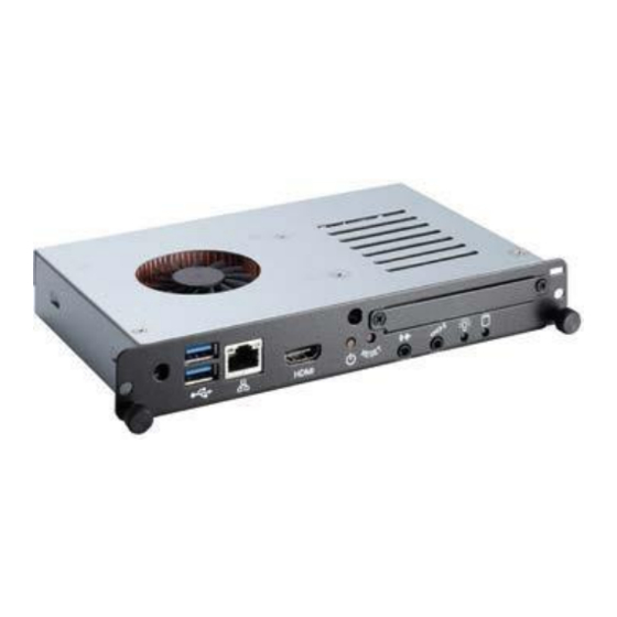
Page 3: Bottom View
•GENERAL VIEW; OPSSL630,OPSSL650 TOP VIEW BOTTOM VIEW Input/Output Connections The connections are illustrated as shown below. 1. HDMI 5. RJ45 10/100/1000 Mbps Ethernet 2. Microphone / Headphone (3.5mm jack) 6. RS232 3. 3 x USB 3.0 ports 7. On/Off Button 4. - Page 4 •GENERAL VIEW; OPSJ1900 TOP VIEW BOTTOM VIEW Input/Output Connections The connections are illustrated as shown below. 1. RJ45 10/100/1000 Mbps Ethernet 5. Reset Button 2. 2 x USB 2.0 ports 6. Microphone (3.5mm jack) 3. Display Port 7. Headphone (3.5mm jack) 4.
- Page 5 •GENERAL VIEW; OPSRK150 TOP VIEW BOTTOM VIEW Input/Output Connections The connections are illustrated as shown below. 1. WIFI Antenna Connector 5. RJ45 10/100 Mbps Ethernet 2. SD Card Slot 6. 2 x USB 2.0 Ports 3. Microphone Port 3.5mm jack 7.
- Page 6 •CONNECTION SCHEME Warning Insert the OPS into the slot with the “This Side Out” warning label facing outside. Your product has an 80 pin OPS standard connection interface. Interconnection of the product and another board (i.e. docking board, monitor board or main board…) is provided by JAE TX/24TX25 plug and receptacle connectors. Left: Plug connector (p/n: TX25-80P) Right: Receptacle connector (p/n: TX24-80P) Plug Connector / TX25 Pinout...
- Page 7 •PIN CONNECTIONS (JAE TX25-80) RSVD Reserved pins Signal Description RSVD Reserved pins DisplayPort RSVD Reserved pins DisplayPort Ground RSVD Reserved pins DisplayPort RSVD Reserved pins DisplayPort RSVD Reserved pins Ground SYS_FAN System Fan Control DisplayPort DisplayPort UART_RXD UART 3.3V Ground UART_TXD UART 3.3V DisplayPort...
-
Page 8: Wireless Lan Transmitter Specifications
•USING YOUR PRODUCT MORE EFFECTIVELY Paying attention to the following points with respect to your product will provide a stable performance and also prolong its life. • Ensuring security of your product • Daily care of your product Daily Care & Environmental Factors Ambient temperature must be between 0°C - 40°C while the product is running. - Page 9 • Replacing HDD & RAM & WIFI ; OPSSL630,OPSSL650 Models Don’t use these sockets SSD COVER RAM1 PL806 DS PROJECTS © APPLICATION ENGINEERING...
- Page 10 • Replacing HDD or SSD; OPSSL630,OPSSL650 , OPSJ1900 Models Holder position should be bottom side. SSD or HDD replace from SSD CVR with 4 screws PL806 DS PROJECTS © APPLICATION ENGINEERING...
- Page 11 • Replacing WIFI, RAM ; OPSJ1900 Models !! Remove 3 screws WIFI RAM 1 RAM 2 PL806 DS PROJECTS © APPLICATION ENGINEERING...
- Page 12 • Docking Board DS PROJECTS © APPLICATION ENGINEERING...
- Page 13 • Docking Board Verification Test after Swapping any component DS PROJECTS © APPLICATION ENGINEERING...
- Page 14 • Power Status DS PROJECTS © APPLICATION ENGINEERING...
- Page 15 • How to Reset Your Windows 10 PC If your computer isn't running the way it should, you're getting strange errors or you just want to return it to its default state, Windows 10 has your answer. The operating system provides a number of options that let you restore your computer to an earlier state.
- Page 16 • How to Reset Your Windows 10 PC 2. Select "Update & security" 3. Click Recovery in the left pane. DS PROJECTS © APPLICATION ENGINEERING...
- Page 17 • How to Reset Your Windows 10 PC Windows presents you with three major options: Reset this PC, Go back to an earlier build and Advanced startup. Reset this PC is the best option for starting fresh. Advanced startup lets you boot off a recovery USB drive or disc and "Go to an earlier build"...
- Page 18 • How to Reset Your Windows 10 PC 5. Click either "Keep my files" or "Remove everything," depending on whether you want to keep your data files intact. Either way, all of your settings will return to their defaults and apps will be uninstalled.
- Page 19 • How to Reset Your Windows 10 PC 7. Click Next if Windows warns you that you won't be able to roll back to a prior version of the OS. 8. Click Reset when prompted. Windows will then restart and take several minutes to reset itself. 9.
- Page 20 • WINDOWS 10 REINSTALLATION VIA USB FLASH DRIVE Requirements; USB Flash Drive which has minimum 16GB capacity, • AIO/OPS device, • Steps; Start Rufus software and install “windows image.iso” file to USB flash drive as shown. (Picture 1) (windows image.iso file can be changed according to type of OPS model.)Rufus application and windows image files shared via Customer Support Usb flash drive should be chosen under Device option.
- Page 21 • WINDOWS 10 REINSTALLATION VIA USB FLASH DRIVE Picture 1 Picture 3 Picture 2 Picture 4 Picture 5 DS PROJECTS © APPLICATION ENGINEERING...
- Page 22 • OPS INTEL Bios Update Procedure Requirements; • USB Flash Drive which has minimum 32MB • Bios Update files are specific for product that will share via Customer Support. Step 1. Copy bios update files in to the Bootable Flash memory. DS PROJECTS ©...
- Page 23 • OPS INTEL Bios Update Procedure Step 2. Plug the Bootable Flash Memory to OPS USB Input Port. Step 3. Plug keyboard to OPS USB Input Port. Step 4. Press power on button and run IWB. Step 5. While Bios Logo shown on the screen, press F7 for Boot Menu. Step 6.
- Page 24 • OPS INTEL Bios Update Procedure Step 7. Run the update batch file “ f.bat” in DOS commad prompt Step 8. “Bios Update Completed Succesfuly” screen shown below. Step 9. Please Unplug-Plug AC 220V power cable after update proses. DS PROJECTS ©...
- Page 25 •OPS ARM SW Update Rockchip Driver Installation 1. Download the ARM-OPS-tool.rar file from the link shared with you. 2. Extract it to your local drive. DS PROJECTS © APPLICATION ENGINEERING...
- Page 26 •OPS ARM SW Update 3. Open Release_DriverAssistant folder. Then double click DriverInstall.exe. Wait till the installation ends. DS PROJECTS © APPLICATION ENGINEERING...
- Page 27 •OPS ARM SW Update 4. Copy “.android” folder to this address “C:\Users\Your_User_Name\”. No need to do these steps again once it has done for the first time usage. DS PROJECTS © APPLICATION ENGINEERING...
- Page 28 •OPS ARM SW Update Adnroid Image Installation 1. Run AndroidTool.exe from “AndroidTool_Release_v2.1\AndroidTool_ Release\” folder DS PROJECTS © APPLICATION ENGINEERING...
- Page 29 •OPS ARM SW Update 2. Connect ARM OPS to your computer via USB OTG cable. 3. Turn on the OPS by pressing the Power On/Off button at least 1-4 sec. from docking board. DS PROJECTS © APPLICATION ENGINEERING...
- Page 30 •OPS ARM SW Update 4. When the Tool is opened, there writes “No Found any Devices” at bottom bar. After the Android boot logo is appeared on the screen, then there will write “Found one MSC Device” NOTE: If label at bottom bar could not turn to “Found one MSC Device”, follow these steps: - Connect a mouse to the ARM OPS.
- Page 31 •OPS ARM SW Update - Select Mass Storage - After these steps there must be written “Found one MSC Device” on the tool. DS PROJECTS © APPLICATION ENGINEERING...
- Page 32 •OPS ARM SW Update - W/ALTERNATIVE WAY If OPS is not connecting as Mass Storage Device, please follow these steps: Unscrew OPS top bracket in order to reach OPS Main Board. Short the J34 with any material(Cable etc). DS PROJECTS ©...
- Page 33 •OPS ARM SW Update - W/ALTERNATIVE WAY If everything is OK. There will write “MASKROM” in red rectangle area. Then Load Image File by clicking the button marked with “1”. A pop-up menu will appear and select Android update image file from here. DS PROJECTS ©...
- Page 34 •OPS ARM SW Update 5. Click “Upgrade Firmware” tab then click “Firmware” button from the tool after then select update.img which is given. 6. Click “Switch” button. This will put ARM OPS into image update mode. 7. Click Upgrade button to start the image update. Then wait till the system opens automatically. DS PROJECTS ©...
- Page 35 •Troubleshooting Guide Some troubleshooting issues are mentioned in this chapter under the following titles: Points to be checked first Frequently asked questions Points to be checked first When a problem occurs, it is very important to diagnose this problem correctly. Try to find out what it is.
- Page 36 •Troubleshooting Guide Some troubleshooting issues are mentioned in this chapter under the following titles: Points to be checked first Frequently asked questions Points to be checked first When a problem occurs, it is very important to diagnose this problem correctly. Try to find out what it is. Determine what causes the problem and under which category it falls.
- Page 37 •Troubleshooting Guide Issues about turning on the system Problem: System does not start. Check The Following: • Steady, long beeps -- This is another POST code that noted a bad power supply. The difference is, while the “steady, short beeps” code notes that the power supply may be bad, this POST code notes that is has gone bad.
- Page 38 THANK YOU Vestel Application Engineering Department HBB- 2017 DS PROJECTS © APPLICATION ENGINEERING...
Need help?
Do you have a question about the OPSJ1900 and is the answer not in the manual?
Questions and answers